A METHOD FOR SELF-CALIBRATION IN SATELLITE WITH HIGH PRECISION OF
SPACE LINEAR ARRAY CAMERA
Wei Liua, Fangming Qiana, Yuzhe Miaoa, Rongjian Wanga
aXi’an
Research Institute of Surveying and Mapping, No. 1 Middle Yanta Road, Xi’an, China, 710054
-
[email protected]aXi’an
Research Institute of Surveying and Mapping, No. 1 Middle Yanta Road, Xi’an, China, 710054
-
[email protected]aXi’an
Research Institute of Surveying and Mapping, No. 1 Middle Yanta Road, Xi’an, China, 710054
-
[email protected]aXi’an Research Institute of Surveying and Mapping, No. 1 Middle Yanta Road, Xi’an, China, 710054
-
[email protected]Commission I, WG I/4
KEY WORDS: Space camera; Self-calibration; Optical auto collimation; Focal length; the optical axis
ABSTRACT:
At present, the on-orbit calibration of the geometric parameters of a space surveying camera is usually processed by data from a ground calibration field after capturing the images. The entire process is very complicated and lengthy and cannot monitor and calibrate the geometric parameters in real time. On the basis of a large number of on-orbit calibrations, we found that owing to the influence of many factors, e.g., weather, it is often difficult to capture images of the ground calibration field. Thus, regular calibration using field data cannot be ensured. This article proposes a real time self-calibration method for a space linear array camera on a satellite using the optical auto collimation principle. A collimating light source and small matrix array CCD devices are installed inside the load system of the satellite; these use the same light path as the linear array camera. We can extract the location changes of the cross marks in the matrix array CCD to determine the real-time variations in the focal length and angle parameters of the linear array camera. The on-orbit status of the camera is rapidly obtained using this method. On one hand, the camera’s change regulation can be mastered accurately and the camera’s attitude can be adjusted in a timely manner to ensure optimal photography; in contrast, self-calibration of the camera aboard the satellite can be realized quickly, which improves the efficiency and reliability of photogrammetric processing.
1. INTRODUCTION
A space camera is a key piece of equipment in obtaining original image information. Affected by changes in vibration, air pressure, temperature, humidity, and other environmental factors during the launch process, the interior orientation elements of the camera and the angle of lens axis between the star camera and ground camera have produced unpredictable changes. Long-term studies show that although these variations seem to be very small, their effects on positioning and mapping accuracy should not be ignored[1]. At present, such cameras are not strictly photogrammetric definition cameras; thus, use of many of the aerial triangulation formulae is not practicable.
At present, to solve the abovementioned problems, a calibration field with a large number of control points is used. When the satellite is overhead, geometric parameters of the camera’s on -orbit flight condition are calculated using the ground control point data, satellite images, orbit data, and attitude data[1]. The entire process is very complex and time consuming. With on-orbit calibration experience from satellites such as TH-1 and ZY-3, we determined that it is difficult to capture the images of a full calibration field owing to the influence of factors such as the weather. Therefore, using the calibration field method makes meeting the needs of on-orbit calibration in a timely manner difficult.
In view of these issues, methods that can directly monitor and calibrate state changes of the satellite camera in real time, or almost in real time, are required. This study presents such a
method; it uses the optical autocollimation principle to achieve real-time monitoring and on-orbit self-calibration of a space linear array camera.
2. SELF-CALIBRATION PRINCIPLE
2.1 Optical autocollimation principle
An important property of the plane mirror is that when the direction of the incoming light is invariant and the plane mirror rotates through an angle
, the reflection light will rotatethrough an angle
2
. This property of flat mirrors can be used in the accurate measurement of space angles. The autocollimation principle has the characteristics of the multidimensional and non-contact measurement of small angles.The autocollimation principle may allow the optical object and image in one plane; that is, it may allow the object and image on conjugate planes. The instrument designed according to this principle is called an autocollimator .The principle of the autocollimator is shown in Figure 1. When a beam of parallel light returns to the objective after exiting it (imaging at infinity) via the reflex of the flat mirror, it forms a real image of the object in the plane. If the mirror and optical axis of the autocollimation has an angle of
, the angle of reflection is
2
. The line displacementS
of the autocollimation image on the focal plane reflects the size of the deflection angle:'
tan 2
S
f
(1) The International Archives of the Photogrammetry, Remote Sensing and Spatial Information Sciences, Volume XLI-B1, 2016XXIII ISPRS Congress, 12–19 July 2016, Prague, Czech Republic
This contribution has been peer-reviewed.
where
f
is the focal length of the objective and2
is the mirror tilt angle.
2
S objective
flat mirror
Figure 1 Principle of autocollimation method
Using the optical autocollimation principle to measure the deflection angle is mature technology that has been widely used in many fields of precision measurement[3]. By improving the traditional autocollimation optical path, it is also possible to achieve three-dimensional angle variable measurements[4] .
2.2 Optical axis location recorder (OALR)
Based on the above understanding of the optical autocollimation principle, we can install a beam of collimation light and small-matrix CCD (SMCCD) devices in the satellite load system. By processing the mark images and extracting and calculating the position change information in the SMCCD, we can obtain real-time on-orbit parameter variations of the camera focal length and attitude angles, which facilitates real-time monitoring and self-calibration of the camera.
Structurally, the optical axis location recorder (OALR) is not a complete unit; it comprises certain spare components, which are separately installed in the camera lens, focal plane, and structural frame base of the load system. Recorder emission components and optical receiver components are installed at the focal plane of the camera. Reticle, collimating light sources, and SMCCD devices to accept the cross images, are installed at both ends of the linear CCD. In this way, the collimating light passes through the internal light path of the camera, the roof prism, and the standard reflecting prism, before returning to the image plane of the SMCCD to form imagery. By calculating the cross-shaped position change in the SMCCD, we can obtain the focal length variation and camera rotation around the optical axis.
linear CCD
emergent ray incident ray
linear CCD
SMCCD , reticle and collimating light sources
standard reflecting prism roof prism
camera lens
SMCCD reticle and collimating light sources
x
y
Figure 2 Basic principles of optical axis position recording equipment
Note: the internal optical structure design of the space camera is very complex; this figure gives just an indication of the basic
principles, some parts of the process are simplified
3. SELF-CALIBRATION DATA PROCESSING
The following parameter variations can be calculated using the data obtained from the OALR:
1. Variation of camera focal length;
2. Rotation of optical axis (X- and Y-axes) relative to the central prism;
3. Rotation of optical axis (Z-axis). 3.1 Variation of camera focal length
When the camera focal length changes, the autocollimation images leave their nominal position and move along the Y-axis, as shown in Figure 3.
L Z
Y Δf X
эф
.
f
эф
.
X
Z Y
L 3
1
5 6 4 2
y01
y11 y02
y22
2 1
Figure 3 Sketch map of autocollimation images when camera focal length changes
(1,2: Recorder receiver (SMCCD); 3,4: Rating positions of OALR autocollimation images; 5,6: positions after change of
OALR autocollimation images)
The variation in camera focal length can be derived by the following formula.
L f y
y y
y
f 11 01 22 02 э ф.
2
(2)
Where
y
01,y
02 are the Y coordinates of the nominalpositions in the OALR channel 1 and channel 2 autocollimation images, respectively;
11
y
,y
22 are the Y coordinates after change in the OALR channel 1 and channel 2 autocollimation images, respectively;
is the SMCCD pixel.3.2 Rotation of camera lens around X axis
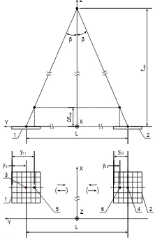
When the optical axis of the camera rotates around the X-axis, the autocollimation images leave their nominal position and move along the Y-axis, as shown in Figure 4.
The International Archives of the Photogrammetry, Remote Sensing and Spatial Information Sciences, Volume XLI-B1, 2016 XXIII ISPRS Congress, 12–19 July 2016, Prague, Czech Republic
This contribution has been peer-reviewed.
L Z
Y X
fэф
.
X
Z Y
y11
Δ Δ
L
y01 y02
y22
3 1 5
2 6 4 2 1
Figure 4 Sketch map of the autocollimation images when the optical axis of the camera rotates around the X-axis
(1–6 are the same as defined in Figure 3)
The rotation angle of the camera around the X-axis can be derived using the following formula.
.
2 02
22 01 11
2
) ( cos 5
. 0
эф
f y y y y
(3)
Where
y
01,y
02 are the Y coordinates of the nominal positions in the OALR channel 1 and channel 2 autocollimation images, respectively;11
y
,y
22 are the Y coordinates after change in the OALR channel 1 and channel 2 autocollimation images, respectively;
is the SMCCD pixel;
is the angle between the center of the SMCCDand the optical axis in the YOZ plane.
3.3 Rotation of camera lens around Y axis
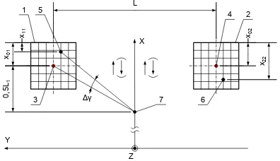
When the optical axis of the camera rotates around the Y axis, the autocollimation images leave their nominal position and move along the X-axis, as shown in Figure 5.
Z
X
Y
X Z
Y
Δα α
f0
0,5L1
0,5L1
x01
x11
x02
x22
1 3 5 2 4 6
L
A
A型
1 2
Figure 5 Sketch map of the autocollimation images when the optical axis of the camera rotates around the Y-axis
(1–6 are the same as defined in Figure 3)
The rotation angle
of the camera around the Y-axis can be derived using the following formula.
.
2 02
22 01 11
2
) ( cos 5
. 0
э ф
f x x x x
(4)
Where
x
01 ,x
02 are the X coordinates of the nominalpositions in the OALR channel 1 and channel 2 autocollimation images, respectively;
11
x
,x
22are the X coordinates after change in the OALR channel 1 and channel 2 autocollimation images, respectively;
is the SMCCD pixel;
is the angle between the center of the SMCCD and the optical axis in the XOZ plane.3.4 Rotation of camera lens around Z axis
When the optical axis of the camera rotates around the Z-axis, the autocollimation images leave their nominal position and move along the X-axis, as shown in Figure 6.
X
Z Y
L
Δ
1 5
3 6
4 2
x01
x11 x02
x22
0
,5L
1
7
Figure 6 Sketch map of the autocollimation images when the optical axis of the camera rotates around the Z-axis The International Archives of the Photogrammetry, Remote Sensing and Spatial Information Sciences, Volume XLI-B1, 2016
XXIII ISPRS Congress, 12–19 July 2016, Prague, Czech Republic
This contribution has been peer-reviewed.
(1–6 are the same as defined in Figure 3; 7 is the center of the focal plane)
Around the lens of the camera view from the angle , the axis can be derived using the following formula.
The rotation angle of the camera around the Z-axis can be derived using the following formula.
autocollimation images, respectively;11
x
,x
22 are the X coordinates after change in the OALR channel 1 and 2 autocollimation images, respectively;
is the SMCCD pixel.3.5 Summary of parameters
Parameters determined by the OALR are summarized in Table 1.
Parameters Calculation formulas Variation in camera
focal length
Rotation of camera lens around X- axis
Rotation of camera lens around Y- axis
Rotation of camera lens around Z- axis
Table 1 Parameters determined by the OALR
4. MEASUREMENT ERROR CALCULATION
Measurement errors can be deduced as in Table 2 using the expressions listed in Table 1.
Parameters Calculation formulas Measurement error of the
camera focal length variation L
эф
Measurement error of camera
lens rotation around X-axis
Measurement error of camera
lens rotation around Y-axis
Measurement error of camera
lens rotation around Z-axis
Table 2 Measurement parameter errors determined by the OALR
Assumptions:
D is the diameter of the SMCCD, 30 pixels;
L is the distance between two SMCCD centers (nominal position of the autocollimation images), 669 mm;
fзΦ is the effective focal length of the camera lens, 6550 mm;
k
is the determined error of the position mark in autocollimation images, as obtained by the correction ofmultiple measures. Under the ground (lab) condition,
kis 0.430; under the flight (gravity) condition,
k is 0.144.Measurement errors of parameters determined by the OALR can be calculated as in Table 3.
Parameters ground (lab) Under the condition
Under the flight (gravity) condition Measurement error of the
variation in camera focal
length f (mm) 0.102 0.034
Measurement error of the rotation of the camera lens
around the X-axis (″) 0.152 0.051 Measurement error of the
rotation of the camera lens
around the Y-axis (″) 0.152 0.051 Measurement error of the
rotation of the camera lens
around the Z-axis (″) 6.396 2.148 Table 3 Measurement errors of parameters determined by the
OALR (3σ)
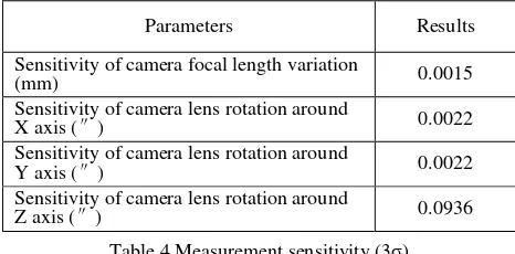
The in-orbit measurement sensitivity can be determined by correcting the random components using the data from multiple readings (9).
Parameters Results
Sensitivity of camera focal length variation
(mm) 0.0015
Sensitivity of camera lens rotation around
X axis (″) 0.0022
Sensitivity of camera lens rotation around
Y axis (″) 0.0022
Sensitivity of camera lens rotation around
Z axis (″) 0.0936
Table 4 Measurement sensitivity (3σ)
From Tables 3 and 4, it can be concluded that this method can achieve high-precision calibration of the variation in camera lens focal length f and its rotation around the X- and Y-axes
and ; the method achieves calibration of the rotation with slightly lower precision around the Z-axis . However, it is well known that position accuracy is mainly determined by
f
, , and ; the impact of is small. Therefore, this method is considered feasible.
REFERENCES
Wei Liu., 2011. In-flight Calibration of Spaceborne Three-Line CCD Camera based on the Equivalent Frame Photo Coordinate, School of Remote Sensing and Information Enginnering, Wuhan University.
Jiyou Zhang., 2004. Photoelectric collimator research present situation and prospect. Measurement technology. 7:27-29.
Gao Yang., 2010. Study on Ship Three-Dimensional Deformations Measurement with OpticalCollimation and Videometrics. Graduate School of National University of Defense Technology.
The International Archives of the Photogrammetry, Remote Sensing and Spatial Information Sciences, Volume XLI-B1, 2016 XXIII ISPRS Congress, 12–19 July 2016, Prague, Czech Republic
This contribution has been peer-reviewed.