JOINT PROCESSING OF UAV IMAGERY AND TERRESTRIAL MOBILE
MAPPING SYSTEM DATA FOR VERY HIGH RESOLUTION CITY MODELING
Armin Gruen1, Xianfeng Huang1,2, Rongjun Qin1, Tangwu Du1, Wei Fang1, Joao Boavida3,Adriano Oliveira3
1 Singapore-ETH Center, Future Cities Laboratory, CREATE, Singapore - [email protected];
[email protected]; [email protected]; [email protected]; [email protected]
2LIESMARS, Wuhan University, China - [email protected] 3
Artescan -3D Scanning Lda, Coimbra, Portugal - [email protected]; [email protected]
KEY WORDS: Unmanned Aerial Vehicle (UAV), Mobile Mapping System (MMS), Data Integration, Modeling
ABSTRACT: Both unmanned aerial vehicle (UAV) technology and Mobile Mapping Systems (MMS) are important
techniques for surveying and mapping. In recent years, the UAV technology has seen tremendous interest, both in the mapping community and in many other fields of application. Carrying off-the shelf digital cameras, the UAV can collect high quality aerial optical images for city modeling using photogrammetric techniques. In addition, a MMS can acquire high density point clouds of ground objects along the roads. The UAV, if operated in an aerial mode, has difficulties in acquiring information of ground objects under the trees and along façades of buildings. On the contrary, the MMS collects accurate point clouds of objects from the ground, together with stereo images, but it suffers from system errors due to loss of GPS signals, and also lacks the information of the roofs. Therefore, both technologies are complementary. This paper focuses on the integration of UAV images, MMS point cloud data and terrestrial images to build very high resolution 3D city models. The work we will show is a practical modeling project of the National University of Singapore (NUS) campus, which includes buildings, some of them very high, roads and other man-made objects, dense tropical vegetation and DTM. This is an intermediate report. We present work in progress.
1. INTRODUCTION
Today 3D city models are important base datasets for many applications, some more traditional, other quite new. The efficient generation of high resolution structured models (not just unstructured surface models for the whole area) is both a relevant research topic and an important issue for the professional practice. Both Unmanned Aerial Vehicles (UAV) and Mobile Laser Scanners (MMS) are important techniques for surveying and mapping. UAV technology, if used in aerial mode, and terrestrial Mobile Mapping Systems (MMS) are complementary technologies. While aerial UAV images are ideally suited to model the roof landscape and part of the terrain, terrestrial point clouds are able to look under the trees and also to represent the façades. If these two datasets are amended by terrestrial images we have most of the primary information needed to generate a complete model 3D city model.
Integration of multiple sensor data can add more information and reduce uncertainties to data processing, also allow for a higher degree of automation. Most of the multi-source data fusion researches are built on data from similar view directions, like the airborne LiDAR point clouds and images from aerial and satellite platforms. For city model reconstruction, the integration of data through the use of complementary data sources can be helpful for both building detection and model reconstruction. However, only few researchers have worked on integrating of data from airborne and ground based sensors. Von Hansen (2008) proposed a method using extracted straight lines to register airborne and terrestrial laser scanning data. Stewart et al. (2009) combined and positioned the terrestrial laser scanning data to airborne LiDAR data to detect ground displacements caused by natural hazards. Rutzinger et al. (2009) proposed a method to extract vertical walls from terrestrial mobile and airborne laser scanning data.
Al-Manasir and Fraser (2006) georeferenced terrestrial laser-scan data with the help of terrestrial images via signalized common points.
On the other hand, most of the past UAV applications are performed in rural or suburban areas, such as cultural heritage site modeling, suburban mapping, agriculture monitoring, etc. (Eisenbeiss, 2009, Gruen et al., 2012). Only few projects are reported about mapping urban areas with UAV, and even more seldom is the combination of UAV images with MMS point clouds for city modeling. How to combine and how to use them are some of the questions to be answered in this paper.
of the geo-referencing of point clouds by using UAV image data, (c) modeling buildings with their façades from laser point clouds and terrestrial images, (d) setting an example of integration of these three data sources for 3D city modeling, which, according to our knowledge, has not been done before. Fusion is done both on the level of data processing and data integration.
2. PROJECT DESCRIPTION
2.1 Main Process Workflow
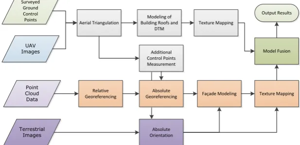
The input of our work is: (1) raw point clouds from MMS; (2) UAV images; (3) few Ground Control Points (GCPs); (4) Terrestrial images for geometric modeling and (5) optional: texture mapping from aerial and terrestrial images. Our working procedure can be generalized into several steps, including:
(a) UAV images aerial triangulation
(b) Integration of UAV- derived control point data to geo-reference and adjust the MMS point cloud data (c) Modeling of the roof landscape from UAV images
(d) Measurement of the DTM from UAV images
(e) 3D modeling of façades from MMS data and (if needed) from terrestrial images (f) Modeling of DTM from MMS data
(g) Fusing façade and roof models and the DTMs to generate a complete geometry model (h) Optional: Texture mapping from aerial and terrestrial images
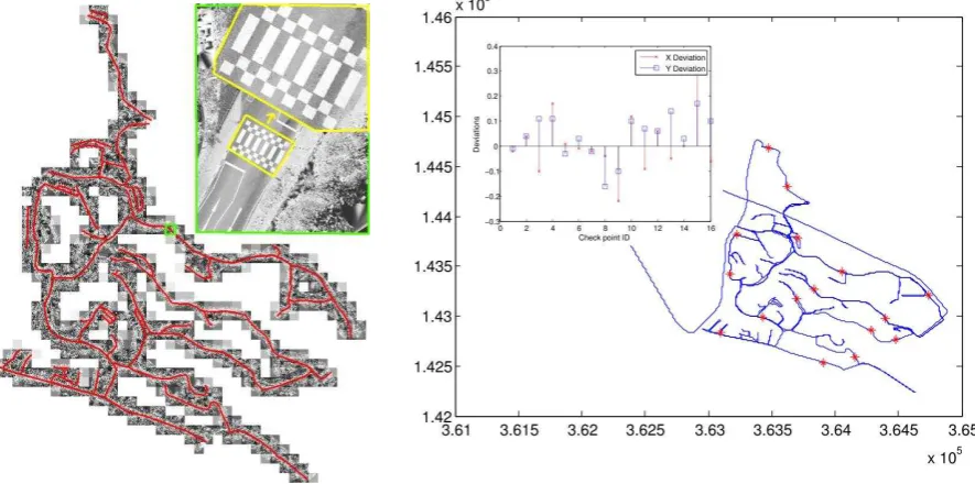
The complete procedure is shown in Figure 1. From the input image data, control points and raw point cloud data, we can achieve a complete 3D site model, achieved by integration of these input data sources. One of our byproduct is a accurately georeferenced point cloud data, derived from existing aerial image data without extra surveying field work. Technologies GmbH, with an off-the-shelf camera Sony Nex-5. It is a two-beam octocopter with 4 rotors on each side, powered by battery. It has a build-in GPS/IMU, a barometer, electronic compass and a stabilizing system for both the camera and the platform. It has up to 300 meters remote controlling distance with a maximal operation slot of 20 minutes. Limited by the flying time, the image data collection over the NUS campus area (2.2 km2) had to be done with 43 starts and landings in 3 days, because each flight collected only a small block of 4x4 or 5x5 images. After data cleaning, we finally got 857 images out of 929 raw images with corresponding GPS/IMU records. The layout of the block is shown in Figure 2 (left). The right part shows a sample image, with 5cm ground resolution.
The Sony Nex-5 is a mirrorless interchangeable-lens camera, with an image dimension of and a pixel size of in both x and y directions. We use its original lens with a fixed focal length of 16 mm. The camera calibration was done in our lab with the software package IWitness, using the point cloud calibration method (Remondino, Fraser, 2006). After calibration a re-projection error of 0.24 pixels is obtained.
developed by French National Geographic Institute (IGN). Given the rough position from GPS of each image, the software can find the relationships between images. Then, the tie points are extracted automatically by SIFT
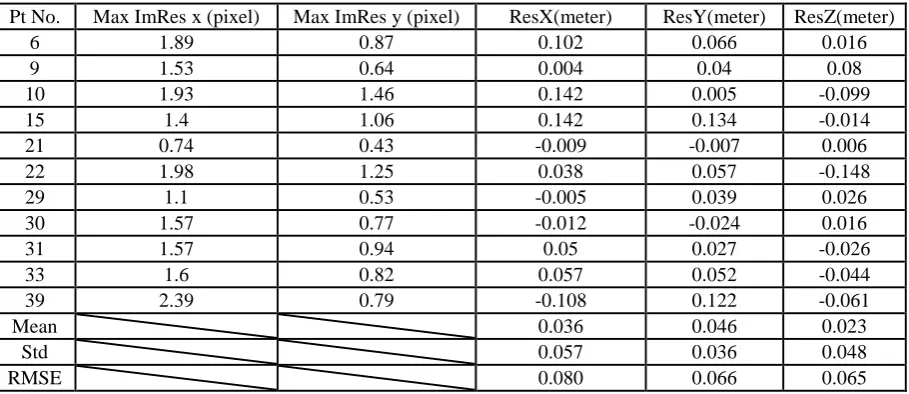
algorithm and a following exhaustive search strategy to deal with failure matching. The result of bundle adjustment using APERO is shown in Table 1. The RMSEs computed from 11 check points give 7 cm planimetric and 6.5 cm height accuracy. These values, slightly above the one-pixel mark (5 cm) are acceptable considering the fact that we are dealing here with natural control and check points.
Figure 2: Layout of the NUS image block (left) and one sample image of a high-rise building (right).
Table 1: Result of bundle adjustment of the full block with APERO. Residuals at check points.
Pt No. Max ImRes x (pixel) Max ImRes y (pixel) ResX(meter) ResY(meter) ResZ(meter)
6 1.89 0.87 0.102 0.066 0.016
9 1.53 0.64 0.004 0.04 0.08
10 1.93 1.46 0.142 0.005 -0.099
15 1.4 1.06 0.142 0.134 -0.014
21 0.74 0.43 -0.009 -0.007 0.006
22 1.98 1.25 0.038 0.057 -0.148
29 1.1 0.53 -0.005 0.039 0.026
30 1.57 0.77 -0.012 -0.024 0.016
31 1.57 0.94 0.05 0.027 -0.026
33 1.6 0.82 0.057 0.052 -0.044
39 2.39 0.79 -0.108 0.122 -0.061
Mean 0.036 0.046 0.023
Std 0.057 0.036 0.048
RMSE 0.080 0.066 0.065
2.3 Georeferencing of Point Cloud Data
Figure 3: Mobile Mapping System (left), example point cloud data at CREATE buildings (middle) and MMS campus trajectory.
Altogether, 34.4 GB of raw point cloud data of 16 km long road sides were collected within 3 hours, with 5.25GB sequences of stereo street images. The point cloud data is stored separately in 54 files.
Figure 3 (right) shows the overview of the colored point cloud data with 700 points/m2 in the middle part of the road. The left part of Figure 4 shows the interpolated intensity data along the trajectory. We interpolated the intensity data with 2.5cm sample space and normalized the intensity values to grey level for visualization, as shown in the upper part of the left image in Figure 4. The intensity data of the point clouds have very stable quality along the road, showing clear corners and edges of road marks, such that it provides great potential for us to measure corresponding points between images and point clouds precisely.
Figure 4: Left: Overview of NUS campus point cloud intensity data. Right: Distribution of check points and their coordinate differences at X and Y directions (Unit: meter).
Point Cloud Data Adjustment
As there are many high buildings and dense trees which partially block the GPS signals, the coordinate accuracy of GPS is not very high, thus influencing negatively the accuracy of the trajectory after fusion of GPS and IMU. The GPS signal losses happen frequently and unpredictably, so it needs many control points to re-georeference the point clouds.
The software used for trajectory adjustments was RIEGL’s RiProcess, designed for managing, processing, and analyzing data acquired with airborne and terrestrial mobile laser scanning systems. A two-step procedure was applied to adjust the data using control point from point clouds. The locations of these control points were chosen regarding criteria like spatial distribution, but also in crossroads where there are overlapping areas from different passages. In these overlapping areas the adjustment was done in two steps, first relative, then absolute to the control points. After the trajectory is adjusted by given control points, the new trajectory is applied to re-calculate the coordinates of point clouds.
Accuracy Evaluation
The data accuracy check is conducted on new measured points, rather than on the control points used in the adjustment. We manually measured 16 points from both UAV stereo images and point cloud data. The check points are evenly distributed over the whole area along the roads, as shown in Figure 4. The check points were measured carefully at the corner of land marks or at places where we could easily identify the corresponding position. Both data sets we used in our evaluation experiment are based on the UTM projection system. But, the height values of the UAV image data is based on WGS84 ellipsoid heights, while the point cloud data carries orthometric heights. As the test area is quite small (only 2.2 km2) and there is no big mountain causing gravity anomalies in such a small area, we can assume that the height differences between orthometric and ellipsoid heights can be replaced by a constant value.
After georeferencing of the point cloud data, the inaccuracy of data due to GPS signal losses will be greatly improved. Before georeferencing the point clouds to the control points we get an average deviation of 0.4 m in planimetry and 0.6 m in height, with a maximal height deviation of 1.3 m. The inset figure in Figure 4 (right) shows the graph of residual distribution at X and Y directions after adjustment. An accuracy analysis of the georeferencing resulted for the 16 check points in the RMSE values of 11 cm for planimetry and 20 cm for height. These are values which could be expected given the cumulative error budget of UAV images and laser-scan point clouds.
3. 3D MODELING COMBINING POINT CLOUD AND IMAGE DATA
3.1 Building Model Reconstruction using UAV Imagery Data
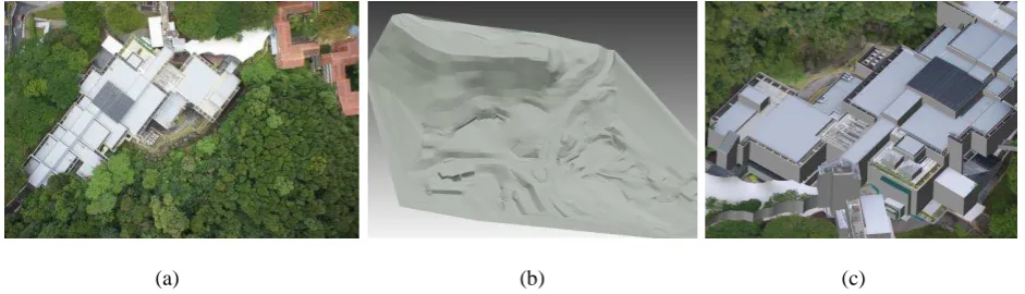
The building models have been created using the semi-automatic modeling software CyberCity Modeler (Gruen, Wang, 1998). Giving weakly ordered key points of roofs measured in a Digital Workstation, following a set of criteria, it will automatically generate roof faces and wall faces, where only a small amount of post-editing is needed. It greatly reduces the operation time for constructing building models and can generate thousands of buildings with a fairly small work force. It is also invariant to model resolution, and is also able to generate fine details on building roofs such as air-condition boxes, water tanks, etc. We used ERDAS StereoAnalyst as Digital Workstation and implemented a converter between StereoAnalyst and CyberCity Modeler. Part of the building and terrain modeling result is shown in Figure 5.
(a) (b) (c)
3.2 Façade Modeling
After georeferencing of the point clouds using control points from UAV data, the two datasets can be registered together. The roof models from stereo UAV images can serve as building contour, which is a compensation for incompleteness of MMS point cloud, thus making it easier to model the façade from occluded point clouds. The façade modeling in this project is done manually in 3ds Max. To make the modeling procedure easier, the point clouds is wrapped into surface mesh model and imported into 3ds Max as reference. The roof model from photogrammetric measurement of the same building is also imported into 3ds Max, they should match the point cloud mesh model. Sometimes, the boundary of the façades from points clouds show a small deviation to the boundary of roofs from UAV images. For parts of the façade without point clouds, the complete façade structure can be deduced from the regular pattern of windows. Moreover, terrestrial or oblique images of façades can also provide further reference for this deduction. Figure 6 shows an example of a complete building model with roof structures and façades.
We also took terrestrial stereo images of an area called “University Town” for 3D façade modeling.
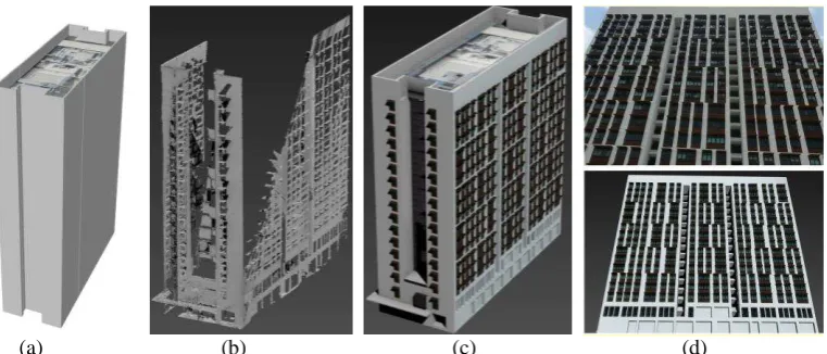
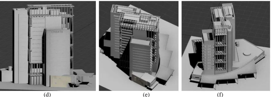
Figure 7 shows the sample data and the modeling results of the most complicated building model in University Town, the CREATE building. This building has a big volume and very complex structures, including solar panels on the roof, bars on the façades to stop the hot wind going up, etc. Actually, the building is so large that one image cannot cover the whole building. We have to measure each part of the roof and then combine the roof parts into a complete model. The façades are modeled using 3D Max from wrapped point clouds. For the detailed structures which cannot be seen from UAV image or Mobile Mapping point clouds, we took terrestrial pictures using a NIKON D7000 camera. With the help from these images, we can model the inside structures. As shown in Figure 7, the detailed structures can be created with the help of integrated multiple data sources.
(a) (b) (c) (d)
Figure 6: Example of a complete building model, (a) roof model from UAV images, (b) wrapped mesh from MMS point clouds, (c) complete model by integrating roofs and façades, (d) façade image (up) and 3D model (down).
(d) (e) (f)
Figure 7: Example of complex CREATE building, (a) an image from UAV; (b) sample point cloud from Mobile Mapping system; (c) terrestrial image sample collected by NIKON D7000; (d)(e)(f) views onto the 3D model of the
CREATE building, produced by integrating the data from UAV, point cloud and terrestrial images.
4. CONCLUSIONS
This paper addresses a project of very high resolution 3D city modeling by integration of UAV images, terrestrial images and MMS data. This pilot project of creating a model of the NUS campus, Singapore delivers many valuable experiences for future applications and research topics: (1) The accuracy of multiple data fusion is carefully evaluated; (2) the experiment shows that using the UAV data to georeference MMS data is feasible and successful and can save a lot of surveying field work; (3) complete building models are created by integration of UAV data, terrestrial images and MMS data.
However, the problems we met in this project also show the directions of our future work: (1) how to improve the level of automation in georeferencing of MMS data? (2) how to improve the accuracy of data registration by utilizing features from both data sources? (3) how to do the micro-adjustment to achieve a perfect match between building roofs with the façade model? The wall extraction method in Rutzinger et al. (2009) provided some insights for us to further investigate this problem. (4) how to improve and speed up the façade modeling procedure ? From our working experience in this project we also found that convenient tools for multi-sensor integrated modeling are still not available, which indicates a topic one should spend more effort on.
The project is work in progress. We still have to process most of the terrestrial images and we also plan to fly UAV oblique images for a certain section of the area to have another useful information channel. This will enter an automated georeferencing and point cloud generation system to compare the results with manual and
semi-automated approaches.
5. REFERENCES
Al-Manasir, K., and C. S. Fraser, 2006. Automatic registration of terrestrial laser scanning data via imagery. Int. Arch. Photogramm. Remote Sens. Spatial Inf. Sci., XXXVI (Part 5), 26-31
Eisenbeiss, H. 2009. UAV photogrammetry. DISS. ETH NO. 18515, doi:10.3929/ethz-a-005939264
Gruen, A. and X. Wang, 1998. CC-Modeler: a topology generator for 3-D city models. ISPRS Journal of Photogrammetry and Remote Sensing. 286-295
Gruen, A., Zhang, Z., and H. Eisenbeiss, 2012. UAV Photogrammetry in remote areas – 3D modeling of Drapham Dzong, Bhutan. Invited Paper ISPRS Congress, Melbourne, Int. Arch. Photogramm. Remote Sens. Spatial Inf. Sci., XXXIX-B1, 375-379, 2012
Remondino, F. and C. Fraser, 2006. Digital camera calibration methods: considerations and comparisons. Int. Arch. Photogramm., Remote Sens. Spatial Inf. Sci., XXXVI (Part 5), 266-272
Stewart, J. P., Hu, J., Kayen, R. E., Lembo Jr, A. J., Collins, B. D., Davis, C. A., and T.D. O’Rourke, 2009. Use of airborne and terrestrial LIDAR to detect ground displacement hazards to water systems. Journal of Surveying Engineering, 135(3), 113-124.