ADAPTIVE TEXTURE SYNTHESIS FOR LARGE SCALE CITY MODELING
G. Despinea, T. Colleua a
SIRADEL, Department of Digital Map Data Production, Research and Development Service, 35760 Saint-Grégoire, France - (gdespine, tcolleu)@siradel.com
Commission V, WG V/4
KEY WORDS: Generic Texture, Window Detection, Texture synthesis, City Modelling, Façade Parsing
ABSTRACT:
Large scale city models textured with aerial images are well suited for bird-eye navigation but generally the image resolution does not allow pedestrian navigation. One solution to face this problem is to use high resolution terrestrial photos but it requires huge amount of manual work to remove occlusions. Another solution is to synthesize generic textures with a set of procedural rules and elementary patterns like bricks, roof tiles, doors and windows. This solution may give realistic textures but with no correlation to the ground truth. Instead of using pure procedural modelling we present a method to extract information from aerial images and adapt the texture synthesis to each building. We describe a workflow allowing the user to drive the information extraction and to select the appropriate texture patterns. We also emphasize the importance to organize the knowledge about elementary pattern in a texture catalogue allowing attaching physical information, semantic attributes and to execute selection requests. Roofs are processed according to the detected building material. Façades are first described in terms of principal colours, then opening positions are detected and some window features are computed. These features allow selecting the most appropriate patterns from the texture catalogue. We experimented this workflow on two samples with 20 cm and 5 cm resolution images. The roof texture synthesis and opening detection were successfully conducted on hundreds of buildings. The window characterization is still sensitive to the distortions inherent to the projection of aerial images onto the facades.
1. INTRODUCTION
1.1 Context and objectives
One activity of the Siradel Company is to produce virtual 3D cities textured with aerial images for architectural or urban planning projects. These models are well suited for bird-eye navigation or to evaluate any urban project but generally the image resolution does not allow pedestrian navigation or detailed view. On the other hand Siradel is leading the Probesim3D research project aiming to produce massive 3D data for military training in simulators. These kinds of simulators usually offer virtual environments close to video game. For this use case the look and feel is as important as the geographic truth: the level of details and the resolution of the textures are essential to improve the immersive feeling of the learner and finally the acceptance of the learning tool.
One solution to face this problem is to increase the resolution by completing aerial images with terrestrial photos. This can be done with a Mobile Mapping System or even with a simple camera. According to our experience, this solution involves huge amount of manual work to remove occlusions (trees, poles,
wires…) and to perfectly fit textures on buildings, even with
automatic process workflow. This is an expensive and time consuming solution that can't be applied to large scale data bases.
Another solution, and this is the object of this paper, is to artificially improve the grain and the level of detail with an adaptive texture synthesis. The idea is to use a procedural modelling strongly constrained with information extracted from aerial low resolution images. The goal here is not to model the
exact ground-truth but to offer a believable low-cost environment that is as close as possible to the real scene.
1.2 Related works
(Alizadehashrafi and Abdul-Rahman 2011) use a Dynamic Pulse Function for texture enhancement. It is based on facet situation and observation for tessellating the textures. Missing faces of polyhedron and missing objects can be solved.
(Loya, 2008) presents a technique for generating abstract representations of buildings in modern urban areas by determining the dominant colours and primary periodic features of a building from textures of facades. A parametric model of building facades as waveforms, based on Fourier series, is used to approximate the facade structure. (Dai, 2013) also details another interesting method for synthesizing realistic façade textures from a simple example. The sample image is parsed and described as semantic components that can be tilled to generate some new facade textures with different dimensions or with occluded parts inpainted.
(Ripperda and Brenner, 2006) propose a formal grammar to derive a structural façade description based on aerial imagery. This description process is guided by statistic distributions of façade structures (e.g. distribution of widows sizes, building
heights, number of stairs …), distributions that are explored using a reversible jump Markov Chain Monte Carlo. This approach is very interesting and close to our problem but the creation of the statistic distribution set is a heavy task and is only valid for a given region of interest.
Procedural modelling based on grammar rules allows fast producing of cost effective generic cities (Parish and Müller, 2001). This process has been improved by an automatic determination of the architectural style (Mathias 2011). A classifier is first trained on a set of façades with identified style then, for each new façade, some descriptors are calculated and a distance to each candidate class is computed. The knowledge of the style allows to choose the appropriate modelling rule.
(Müller, 2007) describes algorithms to automatically derive 3D models of high visual quality from single façade images of arbitrary resolutions. They combine a procedural modelling pipeline of shape grammars with image analysis to derive a meaningful hierarchical façade subdivision.
Texture synthesis usually involves elementary texture patterns representing a small sample of wall bricks or roof tiles. These patterns are repeatable in X and Y covering the whole roof or façade but creating unaesthetic periodic effect. (Cohen 2003) explains a simple stochastic system for non-periodically tiling based on a small set of Wang Tiles (Wang 1965).
This topic is very active and well documented with high quality results. Nevertheless, in most cases, examples show few building configurations and images are of good quality with a low distortion due to perspective. Our industrial needs faces the challenges of large-scale modelling. It led us to develop this intermediated solution between façade comprehensive description and fully generic textures.
2. METHOD PRINCIPLES AND PRODUCTION
FRAMEWORK
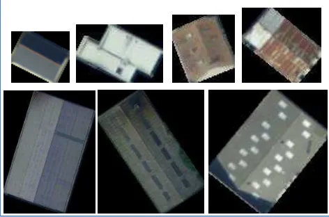
As a digital map data producer Siradel has at its disposal many 3D virtual cities. In these databases, buildings ground outlines are captured with an accuracy of 0.5m and the roofs' main shapes are modelled in 3D. Walls and roofs are textured with aerial imagery with a resolution varying from 5cm to 20cm (Figure 1)
Figure 1. Examples of 20 cm resolution aerial images in real size. Metal, cement and slate roofs: three different building materials
very similar even for human eye.
2.1 General principles
Our method is based on three steps:
1- Detection of information: this step enables to extract information from the image and also geometrical features from
the available 3D model. Various image analysis tools are involved to extract information such as building material (tile,
bricks, concrete…), principal colours of the facades or the position and size of punctual objects like the doors and windows.
2- The Interpretation step is performed by a set of user defined rules allowing refining the raw information from the first step. Here the user can express his knowledge of construction rules and local architectural styles to complete information: by example on low resolution images, it is difficult to distinguish natural slate, bitumen or metal (Figure 1). However the building shape can give indication on the most appropriate material: flat roofs of high buildings are generally made of concrete or bitumen, industrial buildings are covered with metal. The position of windows can also be corrected by this step: roof windows generally do not cross ridge and façade windows are often aligned to each other.
3- The synthesis step is the composition of the final texture. An empty image covering the entire façade or roof area is created with the desired resolution. Then a texture pattern corresponding to the building material is chosen and repeated in X and Y in order to cover the whole façade. For roof we take into account the slope of each roof section to orient correctly the pattern. After that, the process places linear pattern representing objects like cornices or roof-ridges and finishes with punctual pattern like doors or windows. The choice of the patterns is guided by the type of tile should be chosen for ridges. The obtained results are often flat, uniform with an artificial feeling. A radiometric adjustment is then performed. It changes the dynamics so that the average and variance of each channel from the synthesized picture becomes identical to the aerial image. This operation has two advantages: it makes the final texture closer to the reference image and it brings diversity between buildings sharing the same texture pattern. offering the following capabilities: a tool for texture patterns management and the ability to the user to write its own process rules.
2.2.1 Texture Catalogue Manager
Even for manual modelling a graphic designer should pay a great attention to the choice of textures. If he needs to add a window on a façade he must spend time to find the right image corresponding to the correct usage and architectural style. For this task he uses his knowledge and feeling to find the best looking pattern.
Texture synthesis is much more than just a detection problem because all this subjective knowledge and relationship between patterns must be formalized and accessible to automatic process. The International Archives of the Photogrammetry, Remote Sensing and Spatial Information Sciences, Volume XL-5/W4, 2015
For this reason we developed the Texture Catalogue Manager, a tool handling the following aspect:
- Elementary pattern images storage
- Physical information like texture real size or texture tilling mode:
Surface textures are repeatable in 2 directions (X and Y). They represent building materials like tiles or bricks.
Linear textures are repeatable in 1 direction (X or Y): they represent linear objects like cornices, gutters or ridges.
Punctual objects are not repeatable: they represent local details like windows or doors.
- Semantic information (attributes) like the texture usage
(roof, wall…), the building material or its cleanliness, the type of building it is suited for.
- Logical links between textures allowing grouping them by family or style (e.g. a Renaissance style window should be linked to a cut stoned wall texture pattern). These links are very important to ensure a consistent architectural style.
-
Capability to make requests on this database. The selection criterion can mix information such as texture usage, object real size, attributes or logical links.2.2.2 Interactive modelling rules
Procedural tools usually are based on a grammar allowing writing of modelling rules that can lead to very complex reconstruction process. Each rule can use a stochastic behaviour and the chaining of the rules is not deterministic. It is this randomness which creates diversity and makes that no building is similar to another.
Grammar formalization and development of a grammar interpreter are heavy tasks. In our case, even if random takes an important place to create lacking information, the diversity is not the main goal and the modelling process is driven by the aerial image analysis. Thus we decided to simplify the rule management and to restrain the user interactions to three specific tasks:
- In the first task the framework offers to the user various tools to extract information on building shape and texture features. The user can activate or deactivate tools depending on the architectural style of its region of interest. These tools are mainly image classification, pattern recognition and geometry information extraction about buildings.
- The user can then write its own rules to refine the building material: e.g. slates and metal roof are frequently confused by automatic classification but industrial buildings with soft slope are generally covered with metal.
- The last task concerns pattern selection: according to extracted information, the user can write requests to find the most appropriate pattern in the texture catalogue. The requests are based on the following selection criterion :
Texture usage (surface, linear or punctual) Building material
Function (windows, door…)
Any user defined attributes or link (building usage, construction period, architectural style)
Interactions between the user and the framework are implemented with the Angel Script engine1. The script allows the user to write its own rules and to interact with hard coded modules.
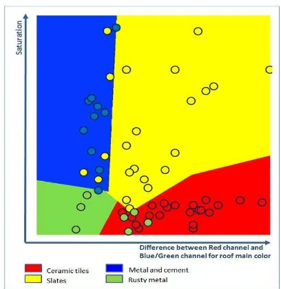
Using this framework we now present two applications. The first experiment concerns the production of roof texture synthesis from aerial images. We then extend our experiment to tackle the problem of façade textures synthesis. classification applied on colour descriptors. The first descriptor is the minimum difference between the red channel and blue or
green channel of the roof’s main colour. This descriptor is good for ceramic tiles or bricks where the red channel is dominant. Since rusty metal roofs are also locally red, we use a second descriptor which is the standard deviation of the hue channel around the red value. To finish, slates, metal or cement are very similar and generally difficult to discriminate even for human eye (Figure 1). However, since their saturation is usually very low we used the S channel of HSV space colour as the third descriptor. Figure 2 shows a visual example of the SVM training step with two descriptors.
Figure 2. Example of SVM roof classification with two descriptors: errors mainly concern confusion between slates and metal classes. 4 rusty roofs are also labelled as Ceramic tiles because of their dominant red colour
Then, the roof-windows are detected. They are generally very dark or very bright compared to the surrounding. Therefore we posterize the image using K-means algorithm with 4 clusters and extract cluster contours. We finally select the candidate contours with geometric criterion like minimal or maximal area as well as compactness and convexity.
1
http://www.angelcode.com/angelscript
Finally, to get a more natural rendering we also introduce material defaults like scratches or fluid flows and light variations by merging the original image with 30% of transparency to the obtained texture (figure 3).
Figure 3. Original texture (a), raw synthesized texture (b) and mixed images with transparency (large and detailed views c, d).
3.2 Results
We tested our algorithms on the Saint-Jacques database, a small city in the suburb of Rennes in north-west of France. The aerial images have a resolution of 20 cm. The testing area presents the following building types: industrial, agricultural sheds, residential areas and apartment or office flats. The roofs are mainly covered with metal for industrial, with bitumen for flats and with natural slates for private houses. For the latter, the main ridge is often made of red ceramic tiles.
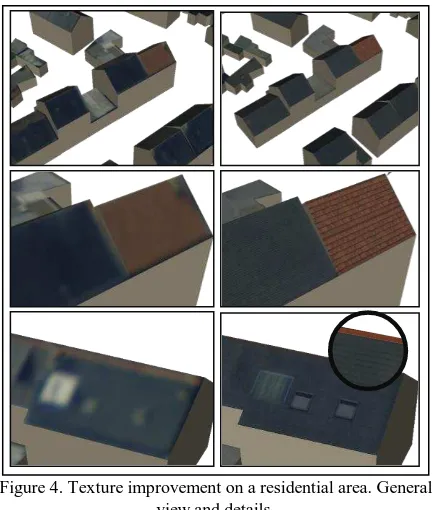
The following snapshots present some of our results (Figure 4). The 503 buildings of our testing area were processed in less than 2 minutes on a very standard computer to produce 2 cm resolution textures.
Figure 4. Texture improvement on a residential area. General
view and details.
One observed problem in the tested data (Figure 5) is related to the lack of 3D superstructures in the geometric models. Indeed, some roof superstructures like dormers are detected but they can
hardly be represented by a simple 2D texture pattern. Instead they should be replaced by a specific 3D model.
Figure 5. Error in object interpretation: the two glass walls are actually dormers, a 3D structure that cannot be represented by a
simple 2D texture
4. FAÇADE TEXTURE SYNTHESIS
4.1 Façade principal colours
The first step while performing façade image reconstruction is to find the background colour of this façade. Some buildings have more than one colour, sometimes the ground floor is darker or for modern buildings some stripes of paint can separate the floors. This colour distribution is generally eye catching and is essential for building recognition by humans. We now explain how we detect these colour variations ( Figure 6).
For this study we only consider the horizontal colour transitions which are the most common cases but similar approach can be used to find vertical stripes. The underlying problem of façade colour description is to answer to the question of "what is wall surface and what is not?". In an image, wall surface can be defined as some clusters of connected pixels with the same colour. The cumulated surface of these clusters should be significant compared to the surface of the whole façade.
We used two simplifications to face our problem: the first is to cut our image into elementary slices and the second is to reduce the colour number for each slice.
For the slice cutting, horizontal edges are first computed with a Sobel filter. This gradient image is stacked horizontally to emphasize the colour transitions. The stack is then thresholded and each local maximum is kept and give the position for the slice cutting. After that, each slice is processed independently. We used the k-means algorithm to posterize the slice and reduce the number of colours to 3. This operation transforms the image slice in a set of adjacent patches of uniform colour. These patches are first filtered with an area threshold then they are referenced in a structure storing the following information for each colour:
- Number of patches for this colour - Cumulated area of patches with this colour - Most representative (greatest) patch of this colour
The local colour for the façade is then the colour which covers the greatest area (cumulated area ) with the fewer patches and with a good compactness for these patches. Note that a simple selection based on the most present colour gives no satisfaction because it can represent other objects than walls like balconies or windows ( Figure 6 d2).
(a) (b)
(c) (d)
Figure 6. Façade principal colours: the gradient image (b) is stacked horizontally giving peaks allowing slices cutting (c). The number of colour is reduced (d) and the distribution of colour patches analysed to find the façade colour (d1) or set it to undef if too scrappy
(d2). Missing colours are deduced from neighbouring slices and close colours merged to give the final image (f)
If the slice's patches are too scrappy the façade colour is set to undefined. Therefore, when all the slices are processed a second step is performed to complete these undefined colours. The average colour of the undef slice if compared to the surrounding slice (one beside and one bellow) and the closest facade colour is set to the current slice.
Finally a corrective step is performed to fuse similar slices and only keep the most representative colours.
4.2 Openings detection
This section now details the detection of facade openings from aerial images. The word “opening” is used for windows, doors, loggias and balconies (the latter is not an opening but indicates the presence of such a one). The proposed method follows the idea of (Martinovic, A. et Al., 2012) in the sense that no shape grammar is imposed to the façade. Instead, openings are detected and refined using weak architectural principles such as size and position. Moreover a hypothesis of row/column structure helps to improve the detection.
The proposed detection consists in two steps. The first one is a pixel-based detection of the facades using machine learning. The second is an object-based detection using architectural constraints. As a post-process, images are first normalized to increase contrast and filtered using mean-shift clustering to reduce noise and enhance edges.
4.2.1 Pixel-based detection using machine learning
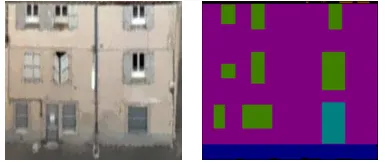
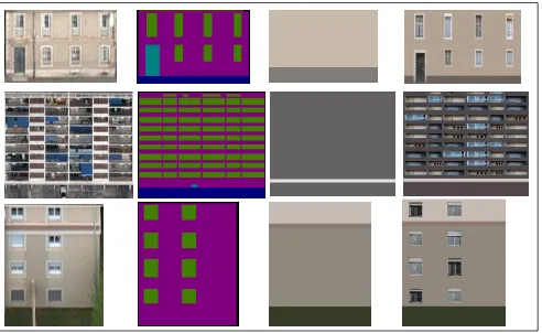
The goal of this process is to analyze the images using only pixel information and a set of training images. To do so, the multi-class segmentation algorithm implemented in the Darwin library is used (Gould, S, 2012) version 1.8.0. First, a set of training images is manually selected and labeled. These images are used to train a conditional random field model (CRF). Several features are computed to train the model: color, texton filters, histogram of oriented gradients (HOG), local binary patterns (LBP), and average over rows and columns. The labeled objects are: background, building, ground, roof, vegetation and opening. At this stage, only windows and doors are labeled as openings in the training images because they have rather regular size and appearance. On the other hand, loggias and balconies are too noisy because they often contain objects like tables, plants, dryers or antennas. Therefore they will be taken into account only in the next step. The output of the pixel-based detection is shown in the second column of Figure 7. The facade in the first example contains few windows and a door. They are all detected although the precision of the contours is not perfect. The second façade
example contains dozens of loggias. They are not detected by the algorithm.
4.2.2 Object-based detection using architectural constraints Architectural constraints are now used to both refine detected openings and detect new openings.
Refinement of detected openings. In the previous step, no information about the façade structure is used. As a result, false detections occur, contours are noisy and openings are not aligned. In order to refine the detection, the following constraints are used: Openings and buildings have often a rectangular shape. Thus they are adjusted to their bounding boxes. Openings have usually width and height in certain intervals of values. Thus, too small or too large openings are removed. Openings are often repeated in rows and columns. Thus, clusters of openings that are almost aligned in rows or columns and have almost the same height/width are refined to be well aligned in positions and size. Doors are usually close to the ground. Thus openings close enough to the ground with a minimum height are classified as door openings.
Detection using repetitions. Openings include a wide variety of shapes and textures. This is particularly true with large buildings made of loggias and balconies. As explained in the pixel-based detection step, only windows and doors were detected. This part now assumes that repeated templates in a façade are likely to be openings, thus the goal is to find repetitions and validate or not the opening hypothesis. Images are processed as follows:
- Compute a mask of opening hypotheses (Figure 8): Horizontal gradients are accumulated vertically and vertical gradients are accumulated horizontally. Local accumulation peaks are detected. The peaks are used to create masks of rows and columns. They are multiplied together to obtain the final mask of openings hypotheses. The third column of Figure 7 shows the resulting mask of hypotheses.
- Opening hypotheses are matched pair-wise to compute a correlation score. A high matching score indicates that the opening is repeated. If the same opening appears at least three times, then the hypothesis is validated.
- Fuse these newly detected openings with previous opening of section 4.2.1.
- Validate by rows and columns: In a row/column of opening hypothesis, if enough openings have been detected, then other hypotheses of the same row/column and same size are validated. The last column of Figure 7 shows the output of this detection using repetitions. In the second row, all the loggias are detected. Note that the detection result is different than the grid of hypotheses because of the matching step and the size constraints that have removed some hypotheses.
(a) (b) (c)
(d1)
(d2)
(e) (f)
Figure 8: Mask of opening hypotheses. (a) Horizontal gradients are accumulated vertically and vertical gradients are accumulated horizontally. (b) Local accumulation peaks are used to create masks of rows and columns. (c) The masks are multiplied to obtain the
final mask of opening hypotheses.
In this process the mask of hypotheses computed from accumulation of gradients gives a nice structure of hypotheses which may not be error-free but provides a convincing visual appearance. Therefore, if the previous detection results in a low ratio of openings compared to the grid of hypotheses, then this grid is used rather than sparse distribution of openings.
4.3 Windows characterization
In the previous section the labelled mask gives the positions and sizes of openings. We now need to find more information about the window type and architectural style.
The resolution of the image sample is not good enough to allow a comprehensive description of the window features. Moreover the perspective introduces important distortion in the windows shape (Figure 9). In these conditions we decided to limit the investigation to very simple tests and reduce the number of windows types to 3 (Figure 10):
- Old style windows - Recent windows
- Loggia (i.e. balcony which does not extrude the façade)
Each type is represented in our catalogue by several family of pattern.
We used a set of simple image procedures. Each procedure will validate (or invalidate) an indicator and the combination of these indicators will help to determine the type of the window. As a procedure can conclude to no result each indicator can take three values: true, false or undefined.
The first indicator is given by the shape of the mask which is more or less equivalent to the windows shape.
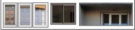
Figure 9. Low resolution, open windows, closed shutters and important distortion due to perspective are obstacle to window characterization
Figure 10. Extract of the texture catalogue with the 3 types of windows (old, new and loggia).
(a) (b) (c)
Figure 7: Original image; Pixel-based detection; Opening hypothesis using accumulation of gradient; Object-based detection The International Archives of the Photogrammetry, Remote Sensing and Spatial Information Sciences, Volume XL-5/W4, 2015
Figure 11. Windows with 1, 2 or 0 "clear" vertical bar
The second indicator is related to the presence of a clear vertical bar at the middle of the windows. It gives indication on the number of glasses. The notion of "clear" is really relative as it can be seen in Figure 11: in the best case the bar is as tall as the window's frame, white and surrounded with dark glasses but sometimes it can be brown, visible only in the upper part of the image or can be occulted by closed shutters. In some cases there is more than one vertical bar or it can be horizontal. As we are looking for a vertical structure the image can be reduced to a single row averaging the corresponding columns. We then research a local maximum near the image centre.
The third indicator is related to the presence of open shutters. Only image wider than 1.5m are considered by this test. The colour space is reduced to 3 levels using the k-means algorithm, then image is divided in 3 parts: the left and right parts are ¼ wide of the total image width. If left and right parts contain shutters they should have a uniform colour. Moreover the colour should be identical for both parts. This predominance is usually obvious in the histogram as it can be seen in Figure 12. In comparison the central part of the window image shows a great variation in colour distribution, some areas are bright and other very dark.
All these indicators are combined with simple heuristics to find the window style (old/new/loggia ):
- Shapes wider than 4m are considered as loggia.
- Generally windows higher than wide are ancient, and windows wider than high are recent.
- Wide windows with only one glass are usually recent. - Windows with panel shutters are old style.
Style, dimension, shutters and number of glasses are combined to request the texture catalogue and find the most appropriate window patterns. If several pattern candidates are returned, one is chosen randomly. For the moment a façade can accept only one type of window which is a limitation to realism.
4.4 Façade texture synthesis results
We conducted our experiment on our Nimes database, a city in the south of France, with an image resolution of 5 cm. Façade characterization is more demanding than roof characterization and the previous database with a resolution of 20 cm was not sufficient.
For the opening detection method, the training set is made of 75 façade images with labels (training labels were manually edited). The test set is composed of 28 façade images. The facades have different architectural styles and size in order to represent the diversity of the city (e.g. individual houses, classical buildings, tall modern buildings). Over a total of 457 openings in the test
The detection obtained with this algorithm gives satisfying results considering the low quality of the images and the great variety of facades. Concerning the assumption that repeated patterns are likely to be openings, only few errors were observed due to repeated patterns that were actually not openings. As shown in Figure 13, one problem comes from precision errors on the position and size of the openings (although alignment constraint is used). To finish, some improvement could be considered: the detection of more objects like balconies and shop windows; automatic choice of thresholds using statistics on the training set; Mask of building occlusions in the images. Moreover more tests will be performed on other cities and with other resolutions.
Figure 13: Precision errors on the position and size of the openings
The results of texture synthesis (Figure 14) are promising but we are still facing problems to generalize the usage of façade texture synthesis to a whole data base. For our point of view the principal limitations are related to these two points:
- The conception of the texture catalogue needs a lot of attention. On one hand a deep reflection must be carry out to find relevant attribute and relations between patterns. On the other hand, some strong graphic designer skills are required to ensure visual consistency in the resulting image.
- In this study, the architectural style (old/recent) research is mainly driven by window characterization. It would be interesting to take into account other façade elements like cornices, balconies, ornaments or even to consider the façade as a whole like in (Mathias 2011). Geometrical information such as building outlines or roof shape can also give clues to its architectural style.
5. CONCLUSION
We present in this study a method to artificially increase the textures quality for 3D virtual cities textured with aerial images. The idea developed here is to use adaptive procedural modelling to add details to the texture. Instead of using pure random modelling we constrain this process by the information that could be extracted from the original aerial images
.
Left
Middle
Right
Figure 12. Shutter detection: the number of colour is reduced to 3, the image is cut in 3 parts at ¼, and ¾ of the width; histograms
show a clear dominance at the same value for both shutters
Initially thought as a pure detection and recognition problem it also appears to be an information management problem: correct texture reconstruction needs good knowledge of the available high resolution patterns and how they should be used together. It is then essential to add semantic information to these patterns, to link them by family or style and to automatically access this information by requests.
The conducted tests are relevant for roof texture modelling and industrial exploitation can now be considered. The façade texture reconstruction is promising but due to façade complexity some complementary works must be achieved, especially in the resolution of architectural style.
REFERENCES
Alizadehashrafi , A. and Abdul-Rahman, A., 2011. Enhancing textures of 3D building façade. In: 10th International Symposium & Exhibition on Geoinformation (ISG 2011) & ISPRS Commission II/5 & II/7 Conference , Shah Alam, Malesia.
Cohen, M. et Al., 2003. Wang Tiles for image and texture generation. In ACM Transactions on Graphics (TOG) - Proceedings of ACM SIGGRAPH 2003, San Diego, USA, Volume 22 Issue 3, pp 287-294.
Dai, D. et Al., 2013. Example-based facade texture synthesis. In: IEEE International Conference on Computer Vision (ICCV), Sydney,Australia, pp 1065-1072.
Gould, S, 2012. DARWIN: A Framework for Machine Learning and Computer Vision Research and Development. In: Journal of Machine Learning Research (JMLR), pp: 3533−3537.
Loya, A. et Al., 2008. A Practical Approach to Image-Guided Building Façade Abstraction. In: Computer Graphics International, Istanbul, Turkey.
Martinovic, A. et Al., 2012. A Three-layered Approach to Facade Parsing. In: Proceedings of the 12th European Conference on Computer Vision, Florence, Italy, Vol. VII, pp 416-429.
Mathias, M. et Al., 2011. Automatic Architectural Style Recognition. In: ISPRS - International Archives of the Photogrammetry, Remote Sensing and Spatial Information Sciences, Volume XXXVIII-5/W16, 2011, pp.171-176.
Müller, P. et Al., 2007. Image-based Procedural Modeling of Facades. ACM. Transactions on Graphics, Vol. 26, pp. 85.
Parish, Y. and Müller, P., 2001. Procedural modeling of cities. In: SIGGRAPH '01 Proceedings of the 28th annual conference. on Computer graphics and interactive techniques, Los Angeles, USA, pp: 301-308
Ripperda, N. and Brenner, C., 2006. Reconstruction of Façade Structures Using a Formal Grammar and RjMCMC. In: Pattern Recognition, 28th DAGM Symposium, Berlin, Germany, Lecture Notes in Computer Science Volume 4174, pp 750-759.
Wang, H. 1965. Games, logic, and computers. In: Scientific American (November), pp: 98-106.
Figure 14. Texture synthesis results for facades