PHOTOGRAMMETRIC MISSION PLANNER FOR RPAS
F. Gandor, M. Rehak, J. Skaloud
École Polytechnique Fédérale de Lausanne (EPFL), Switzerland – (florian.gandor, martin.rehak, jan.skaloud)@epfl.ch
KEY WORDS: mission planning, RPAS, MAV, GPS quality, photogrammetry
ABSTRACT:
This paper presents a development of an open-source flight planning tool for Remotely Piloted Aircraft Systems (RPAS) that is dedicated to high-precision photogrammetric mapping. This tool contains planning functions that are usually available in professional mapping systems for manned aircrafts as well as new features related to GPS signal masking in complex (e.g. mountainous) terrain. The application is based on the open-source Java SDK (Software Development Kit) World Wind from NASA that contains the main geospatial components facilitating the development itself. Besides standard planning functions known from other mission planners, we mainly focus on additional features dealing with safety and accuracy, such as GPS quality assessment. The need for the development came as a response for unifying mission planning across different platforms (e.g. rotary or fixed wing) operating over terrain of different complexity. A special attention is given to the user interface, that is intuitive to use and cost-effective with respect to computer resources.
1. INTRODUCTION
The deployment of civilian RPAS for mapping purposes has become very popular over the last few years. A variety of platforms is equipped with sophisticated imaging and navigation instruments together constituting serious photogrammetric tools (Colomina and Molina, 2014). An indisputable task of every RPAS mission is planning. This process considers mapping requirements and platform characteristics against a-priori information about the mapping site. Indeed, thorough mission preparation is a prerequisite for obtaining satisfactory results while assuming compliance with specific legislation restrictions.
Flying in challenging areas, such as hilly or mountainous areas, requires to extend planning functionalities beyond the common features as 2D zone definition and waypoint layout based on ground sampling distance (GSD) and overlap criteria. By combining real 3D terrain awareness into mission planning with some advanced functions, the proposed tool facilitates the process of mission preparation. Despite the globally available terrain model, the user can use custom digital elevation models (surface included) of high resolution to improve the planning of photo positions with respect to the area of coverage, overlaps and resolution. Thus, the risk of having uncovered areas is significantly reduced. Furthermore, the prediction on GPS signal quality reception can be evaluated within this tool for a specific time and area in order to determine the best time for performing the survey.
An important point that shall be taken into account in planning a mission is the safety. The civil aviation institutions of many countries are working on defining proper rules and regulations to increase safety of RPAS operations (EASA European Aviation Safety Agency, 2015). The goal is to have a regulatory system that is as uniform as possible among countries. One of the common constrains is to maintain a direct line of sight between the operator and the RPAS without artificial enhancements of vision e.g. binoculars or first person view
(FPV) equipment. Furthermore, no-fly zones such as airports should be clearly indicated in the map. The presented mission planner accommodates tools for checking these conditions and alerts user in case of non-conformity.
The paper is divided into following sections. The first part discusses the problematic in the field of RPAS mission planning. In the second part, we describe our development. The last part draws conclusions and presents ideas for future development.
1.1 Requirements on RPAS mission planning
Photogrammetric mission planning can be defined as the planning process of the locations to fly (waypoints) and the vehicle actions to do, e.g. taking a picture, typically over a time period. The functionality of planning is often connected to the mission control but in principal can be separated. The planning part for RPAS is indeed similar to that of a manned airborne vehicle which has been thoroughly developed over decades as the mapping evolved from analogue to the digital, e.g. see (Leica, 2012) for planes or (Schaer and Skaloud, 2007) for close-range helicopter mapping. Hence, the mission planners can be real-time connected to the RPAS or serve only for complementary offline planning. The presented software is in its current state an offline mission planner through which a user can conveniently plan missions but not directly execute them. Some mission planning tools support also systematic repetitions of the RPAS survey flight for situation awareness or research purposes. When an operator plans a mapping mission, success depends on many variables. The mission plan must weigh the capabilities of the RPAS and its sensor package against the quality of information required at each mapping location. A planning algorithm should provide feasible and flyable optimal trajectory that connects each waypoint. These criteria are generally related to the mapping needs.
The essential steps of every photogrammetric mission planning are:
Define a region of interest
Verify possible obstacles and restricted zones Take into account the platform constrains, e.g.
endurance, payload capacity, min/max speed
Set the photogrammetric parameters such as overlaps, resolution and camera parameters
Take into account the terrain morphology Identify the take-off and landing positions points Design and modify the waypoint mission
1.2 State of the art in RPAS mission planning
The market offers nowadays hundreds of different platforms that are all coupled with various mission planners. These planners can be divided into three main categories. First, proprietary and dedicated to a specific platform. These are for example eMotion (senseFly, 2015) or MAVinci Desktop (MAVinci, 2015), both dedicated to fixed wing platforms. Examples of multicopters are Mikrokopter Tool (HiSystems, 2015), mdCockpit (Microdrones, 2015) or DJI Ground Station (DJI, 2015). The proprietary mission planners feature a tight integration of platform’s characteristics into the planning and therefore do not allow to change vital properties related to the flight dynamics. On the other hand, these mission planners are usually very easy to use as many parameters are defined implicitly, which decreases software complexity. Furthermore, real-time monitoring or pre-flight mission simulation are integrated to a common software package.
The second category are open-source mission planners. These are often highly customable tools and based on do-it-yourself projects, such as ArduPilot (Ardupilot, 2015). The open-source mission planners contain a variety of functions making them very universal, however, not very suitable for certain tasks. One of such tasks is photogrammetric mission planning in challenging terrain. The most popular open-source project Mission Planner (Oborne, 2015) lacks advanced mapping features such as visual 3D planning or splitting long flights into separate missions. The lack of visual 3D planning decreases the capability of detecting altitude boundaries and may lead to critical situations especially in highly structured terrain. Other mission planner fitting into this category is QGroundControl (Meier, 2010) that includes mission control for all kind of autonomous unmanned systems. Its high versatility is in contrast with user friendliness. There, less experienced users may find mission planning too difficult or less intuitive contrary to the proprietary systems.
The universal mission planners fall into in the third category. They are not dedicated to a specific platform. One of them is Universal ground Control Station (SPH Engineering, 2015) that can control in real-time a variety of platforms. It basically benefits from both latter categories despite being relatively easy to use. The described toll also belongs to this category but without the ambition of mission control.
2. SOFTWARE DESIGN AND IMPLEMENTATION
2.1 Programming environment
The presented mission planner was developed with aim to facilitate the planning of high-resolution and high-accuracy photogrammetric missions. Although the project is not yet in a mature state, most of the functions are already available. It is built on the open-source Java Software Development Kit called World Wind (NASA, 2011). It features a high-performance 3D virtual globe, basic digital elevation model and includes a variety of demos and examples for fast implementation of custom functions.
The main reasons for choosing the World Wind as a developing environment are the following: 1. The open source and high-performance 3D virtual globe SDK allows to add custom functionalities without starting from scratch. 2. Applications created in the SDK are available on all java supporting operating systems including mobile devices (Linux, Mac OS, Windows, Solaris, etc.). 3. Several standard I/O formats as GeoTIFF and Shapefile are handled with already implemented methods. 4. It includes protocols to access Web Mapping Services (WMS) and Web Feature Service (WFS) such as Bing Maps or OpenStreetMaps. 5. It includes a Global Digital Elevation Model SRTM (Shuttle Radar Topographic Mission), (NASA, 2014) and various methods (e.g. Raycasting Support to find terrain intersection). 6. Numerous demos and examples are provided to facilitate the development.
The geodetic system used in the mission planner is the World Geodetic System 1984 (WGS84) as it is both used in the World Wind framework and in the export that interfaces with the mission control software. Geographical coordinates are mostly used within the planning tool, however, projections as local transverse Mercator are also employed to compute surfaces or distances. Regarding the orthometric heights, World Wind uses the Earth Gravitational Model of 1996 (EGM96).
One of the requirements is to visualize and lay down efficiently the trajectory and related information. The presented mission planner features:
3D mapping environment Input of custom digital models
Checking satellites (GPS) availability along the trajectory and estimate the best survey time
Safety features such as checking the visual line of sight, geo-fence, restricted areas
Compatibility with a variety of autopilots
Generating the trajectory depending on the starting position, the landing position and mapping parameters in 3D terrain
GIS functions for terrain slope and aspect computation
2.2 Mission Planner Interface
The Graphical User Interface (GUI) of the software can be decomposed into two main elements: the map window and tool bars. The main window represents the virtual 3D globe and depicts the base 3D terrain map, the planned trajectory and other auxiliary entities. The tool bars are placed around the main window and serve for setting the mission parameters. Additionally, when using statistical functions for quality The International Archives of the Photogrammetry, Remote Sensing and Spatial Information Sciences, Volume XL-1/W4, 2015
Figure 1: Advanced Graphic environment for RPAS mission planning
2.3 Calculation with custom digital elevation models
According to the mission goals and availability of information the user can load different kinds of base maps. These are often WMS map layers or Shapefiles. Additionally, the user may import a custom digital elevation or surface model of higher resolution than the standard global one. A detailed surface model allows safer planning as it incorporates obstacles such as trees, buildings etc. Furthermore, as the model height is used to compute the optimal flying height considering the desired GSD, the model of higher resolution increases the chance of controlling better this parameter throughout the mission. Additionally, the software allows to perform terrain analysis e.g. slope and aspect, and visualize its outcomes. This is particularly useful in mountainous areas, Figure 2.
Figure 2: Analysis of the digital terrain model; slope analysis
2.4 Trajectory design
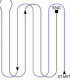
2.4.1 General planning: After selecting the area to be scanned, the user has on option of defining a camera and RPAS devices or choosing from some predefined systems. The latter are stored in a CSV (Comma-Separated Values) files and therefore can be easily modified or extended. Camera parameters of interior orientation and its direction and inclination can be modified directly in the panels. One of the important constraints, which is stored in the platforms attributes, is the platform turning radius. This is particularly important for fixed wing RPAS. The turning radius is important as it affects the dynamic layout of waypoints. A special guidance option was created to handle the turning radius for the fixed wing platforms even if the consecutive flight lines are very close. The user has an option of choosing between alternative flying patters, Figure 3, and so-called smoothing curves. The latter adds a few waypoints at the end of each line to respect the turning radius and better guide the plane to the subsequent line.
Figure 3: Alternative flying pattern
The trajectory plan is calculated automatically. The user can rotate the flight lines in order to better accommodate the influence of wind. For helicopters or multirotor platforms, the camera can be usually tilted to a desired angle in pitch direction. Hence, a function for automatic determination of camera tilt angle was implemented. This is particularly useful in hilly terrain, during inspections of facades or rock walls.
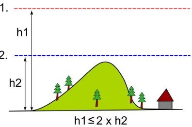
2.4.2 Multi-level flight: Guaranteeing certain ground resolution is an important requirement to fulfil when designing a flight pattern. This can be particularly problematic in hilly or mountainous terrain. We propose a function for multi-level flight pattern that assures unified resolution over the whole mapping area. The height is calculated relatively to the terrain or to the home position altitude. Next, the base height level is accompanied by a second level that is placed above with perpendicular orientation to the first level. The separation between them is calculated in relation to the desired resolution so the average predicted resolution is maintained for the whole area. Furthermore, flying at two separate heights improve the geometry during the 3D scene reconstruction (Pothou et al., 2004). The situation is depicted in Figure 4.
Figure 4: Multi-level flight
2.5 Quality Assessment and Safety Features
2.5.1 Prediction of GPS signal quality: Good reception of GPS during the whole mission is a critical factor that affects the navigation of RPAS as well as the accuracy of the final mapping product. When a platform performs an autonomous waypoint to waypoint flight, the navigation mainly relies on regular GPS position fixes and therefore a good reception of GPS signals is essential for safety. The advantage of GPS for mapping depends on receiver type and scene configuration as discussed for example in (Rehak et al., 2014). In order to predict the best survey time and to overcome the possible unexpected GPS outage caused by signal obstruction, the geometry of the satellite constellation along the planned path is assessed within the planner itself with respect to the elevation model.
The position of the GPS satellites is computed from an almanac using equations of Keplerian orbits. Then, a ray between the mission points and satellites positions are tested for intersection with the terrain. The criteria for these evaluations (e.g. trajectory sampling, time-span, elevation mask etc.) can be modified by the user. Figure 5 shows the imaginary rays between satellites and significant points in the mission for
a specific time interval. It is possible to evoke plots showing the number of visible satellites, (Figure 6) and dilution of precision (DOP) values for analysis.
Figure 5: Visibility of GPS satellites for certain points
Figure 6: Minimum number of GPS satellites as a function of survey time for a specific trajectory
2.5.2 Direct line of sight: The line of sight between the operator and the drone is computed similarly to the approach evaluating GPS signal reception. The algorithm samples the RPAS trajectory and tests the intersection with the terrain at discrete intervals. Two positions concerning the observer and the moving drone are needed to compute the vector between them. The norm of the vector divided by the interval distance gives the number of point to be tested. The elevation of the points along the vector are tested against the elevation of the terrain at the same coordinates. If the terrain is higher, the visibility is declared as masked for this portion of trajectory.
2.5.3 Flight statistics: Certain flight statistics help users to plan mission in safer and more economical way. The platforms characteristics, such as endurance and cruising speed, are important for a correct estimation of the total flying time. The program can estimate the overall flying time from these parameters and the user is informed if the specific mission can be executed within one flight or not. Additional information about covered area, number of images, flight length etc. is provided in one of the info panels.
2.6 Post-flight analysis
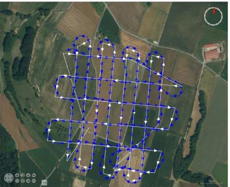
The mission planner contains functions for reading and interpreting the autopilot’s files with the stored path. The actual flight trajectory can be then loaded and compared to the original plan. The projection centres of the images can be displayed in 3D on the map and provide an overview of coverage. Later, this function will be connected with attitude information, which allows projecting the images on the terrain and controlling their real coverage, overlap and GSD. The Figure 7 illustrates a planned versus executed multilevel flight.
Figure 7: Post-mission analysis; blue path: the executed flight, white path: planned path
3. CONCLUSION
Mission planning and real-time mission management subsystems are the key to a competitive exploitation of RPAS for photogrammetry and remote sensing. In this paper, we presented a new tool for RPAS mission planning. The system features off-line mission planning in high resolution 3D space. A survey area can be rapidly drawn to generate automatically flight lines with a layout respecting the end-product characteristics. Platform constraints related to the utilized RPAS are respected in this design. Rough terrain is handled by planning flight pattern with two levels. The automated proposition of trajectory path can be completed by adding waypoints at some desired locations. Digital elevation models can be imported in order to work with custom high-precision elevation information. These elevation models allow to analyse better the terrain and fine-tune the inclined trajectory that respects the end-product requirements. The availability of satellite signal reception and the dilution of precision are also accessible within the planner helping to choose adequate survey time. All parameters and methods are accessible through an interactive graphical interface within the application.
The future development will focus on communication with the autopilot to facilitate the real-time monitoring and real-time quality control of the mapping mission. Similarly to mission planners for mature platforms, also an in-flight quality assessment is important for achieving the efficiency of accurate mapping.
4. REFERENCES
Ardupilot, 2015. ArduPilot. Open-source auto pilot, http://ardupilot.com/.
Colomina, I., Molina, P., 2014. Unmanned aerial systems for photogrammetry and remote sensing: A review. ISPRS Journal of Photogrammetry & Remote Sensing 92, 79–97.
DJI, 2015. PC Ground Station. Dajiang Innovation Technology Inc., China, http://www.dji.com/product/pc-ground-station/feature.
EASA European Aviation Safety Agency, 2015. Unmanned Aircraft Systems (UAS) and Remotely Piloted Aircraft Systems (RPAS), https://easa.europa.eu/unmanned-aircraft-systems-uas-and-remotely-piloted-aircraft-systems-rpas (accessed 1.7.15).
HiSystems, 2015. Mikrokopter-Tool OSD. HiSystems GmbH, Germany.
Leica, 2012. MissionPro. Leica Geosystems, http://www.leica-geosystems.com/en/Leica-MissionPro_98219.htm.
MAVinci, 2015. MAVinci Desktop. MAVinci GmbH, Germany, http://www.mavinci.de/en/completesys/desktop.
Meier, L., 2010. QGroundControl, http://qgroundcontrol.org/.
Microdrones, 2015. mdCockpit. Microdrones GmbH, Germany.
NASA, 2014. Shuttle Radar Topography Mission, http://www2.jpl.nasa.gov/srtm/.
NASA, 2011. World Wind, http://worldwind.arc.nasa.gov/java/.
Oborne, M., 2015. Mission Planner,
http://planner.ardupilot.com.
Pothou, A., Stamatiou, C., Georgopoulos, A., 2004. Performance Evaluation of Multiple Scale Automatic Aerial Triangulation. Presented at the ISPRS Congress, Istambul, Turkey, pp. 595–600.
Rehak, M., Mabillard, R., Skaloud, J., 2014. A micro aerial vehicle with precise position and attitude sensors. Photogrammetrie, Fernerkundung, Geoinformation (PFG) 4, 239–251. doi:10.1127/1432-8364/2014/0220
Schaer, P., Skaloud, J., 2007. ALS Mission Planner. EPFL internal software.
senseFly, 2015. eMotion. senseFly, Switzerland, https://www.sensefly.com/drones/emotion.html.
SPH Engineering, 2015. Universal Ground Control Station (UgCS). SPH Engineering, Latvia, http://www.ugcs.com/en/. The International Archives of the Photogrammetry, Remote Sensing and Spatial Information Sciences, Volume XL-1/W4, 2015