MEASURING THE COSEISMIC DISPLACEMENTS OF 2010 Ms7.1 Yushu
EARTHQUAKE BY USING SAR AND HIGH RESOLUTION OPTICAL SATELLITE
IMAGES
Li Zhang 1, Jicang Wu 1, Feng Shi 2
1Dept. of Surveying and Geomatic, Tongji University, Shanghai, [email protected] 2Institute of Geology, China Earthquake Administration,Beijing, [email protected]
Commission III, WG III/3
KEY WORDS:Co-seismic displacements, D-InSAR, MAI, Optical image matching, PALSAR, SPOT
ABSTRACT:
After the 2010, Mw7.1, Yushu earthquake, many researchers have conducted detail investigations of the surface rupture zone by optical image interpretation, field surveying and inversion of seismic waves. However, how larger of the crustal deformation area caused by the earthquake and the quantitative co-seismic displacements are still not available. In this paper, we first take advantage of D-InSAR, MAI, and optical image matching methods to determine the whole co-seismic displacement fields. Two PALSAR images and two SPOT5 images before and after the earthquake are processed and the co-seismic displacements at the surface rupture zone and far field are obtained. The results are consistent with the field investigations, which illustrates the rationality of the application of optical image matching technology in the earthquake.
1. INTRODUCTION
Differential Interferometric Synthetic Aperture Radar (D-InSAR) is one of the most promising technology in remote sensing field in recent years. It can obtain a wide range of surface deformation with high precision and high spatial resolution, which is widely applied in earthquake researches, such as co-seismic deformation field detection. However, the surface deformation measured from D-InSAR is actually the projection of the true ground displacement vectors along the line of sight (LOS) direction.
Bechor and Zebker (Bechor, 2006) proposed a new method of azimuth displacement estimation, Multi-Aperture InSAR (MAI). The rationale of MAI method is to use the Azimuth Common Band Filtering (ACBF) to split the SAR spectrum along azimuth direction into forward- and backward-looking images and then form two different-looking interferograms. The differential of the two interferograms is the MAI interferogram. By using the relationship between the MAI phase and the azimuth displacement along track, we can obtain the azimuth deformation.
With the development of optical images in precise orthographical correction, registration and pixel analysis, some scholars began to focus on the optical image matching technology. They calculated the offset between the optical images corresponding to pixels by using high spatial resolution of optical images. The method is based on the phase correlation technique and the theory of Fourier migration (Alan, 1999). After removing the orbital error, system error and the satellite platform attitude change, the offset is the surface deformation during the acquisition of the two images.
In this study, DInSAR, MAI, and the optical image matching phase difference caused by minor surface deformation. However, in practical terms, the accuracy of this technology is affected by many factors, such as phase decoherence, DEM errors, orbital errors, atmospheric phase delay and white noise and so on. Considering these influence factors, the interference phase model can be written as: surface;topomeans topographic phase, produced by topographic
changes (relative to reference ellipsoid);defmeans deformation
phase, caused by the surface displacement between the two images; noisemeans the phase caused by various noises.
According to the methods of removing topographic phase, the D-InSAR technique usually has three types, two-pass, three-pass and four-three-pass. The method adopted in this paper is "two-pass", which is used for topographic correction through two SAR images and external DEM (Massonnet, 1993).
3. MAI
We assume M and S represents master image and slave image of one interferogram, respectively. According the principle of MAI, master image can be divided into two SLC images,
f
M andMb. Slave image can be similarly divided into two SLC
images, Sf andSb. Then they can be processed by the routine
procedure of D-InSAR, including registration, multi-look, interference, remove of flat phase and topographic phase, filter
and so on. We use Mf and
S
f to form the forwardinterferogram by f M Sf f
. Samely, the backward interferogram
can be formed by b M Sb b
. Finally, the MAI interferogram is obtained by the phase difference between the two interferograms above:
ΦMAI Φf Φb (2)
The azimuth displacement has the following relationship with MAI interferogram:
coefficient of the normalized view angle. In this paper, n is 0.5 and l is 8.9m. It means that a fringe in the MAI interferogram represents the surface displacement of 8.9 m in azimuth direction (Jung, 2013).
In addition, the baseline error caused by the slight difference of perpendicular baseline may affect the accuracy of MAI interferometric phase. According to the existing documents (Jung, 2009), we can conclude that, the residual flat phase is much bigger than the residual topographic phase caused by baseline error. Therefore, in this paper, we adopt a polynomial model commonly used in InSAR to simulate the error.
We assume that the MAI phase of a pixel in the image (x, r) is
MAI
, it mainly includes the following parts
MAI azi flat topo noise
(4)
where, azi means the phase caused by azimuth
deformation;flat means the phase caused by the residual flat
phase;topomeans the phase caused by the residual topographic
phase; noise is noise phase. Therefore, when we fit the
polynomial model, we must select the representative sample points. They should meet the following requirements: 1) high coherence, which can ignore the noise phase 2) in the non-deformation area, the non-deformation phase can be ignored 3) on flatten area, the residual topographic phase is a very small. Due to the residual reference phase usually shows a linear trend, we adopt a quadratic polynomial to fit this model using the pixel points that meet the above requirements:
2 20 1 2 3 4 5
,
flat x r a a x a r a xr a x a r
(5)
where, x and r represents the coordinate of the sample points in
azimuth and range respectively; a0,a1,…a5are the model parameters that need to be estimated.
4. OPTICAL IMAGE MATCHING
Optical image matching technology is not affected by time decoherence, as well as the maximum deformation gradient limit (Baran, 2005). What’s more, this method takes advantage of gray matching, instead of the phase unwrapping, thus it can obtain the effective surface deformation values.
The process of this method can be summarized as following processes. First, the orthographic correction of two remote sensing images before and after the earthquake is carried out. Second, the Fourier transform is performed on the amplitude of the image after the orthographic correction. Then, the standard cross-spectrum is used to calculate the offsets between pixels. At last, we can get the surface deformation by removing the topographic offset, orbit offset and systematic errors.
The surface deformation caused by the earthquake usually ranges from several tens of centimeters to a few meters, so the accuracy of deformation monitoring must be at the centimeter level. Using the optical image matching technology to monitor the surface deformation, the accuracy of deformation depends greatly on the accuracy of the registration (Leprince, 2008). Therefore, the two remote sensing images before and after the earthquake must be registered with high precision.
Because of the high precision of the Fourier theory (Alan, 1999), the offsets between the two images can be handled accurately.
represent Fourier transforms of two images,
respectively. u and vrepresent frequency changes on rows and columns, respectively. Then we can obtain the relationship between them:
where, Wrepresents the weighted matrix.
The corresponding normalized cross-spectrum is noted as
,Q u v , the relative offsets of the two images are obtained to
minimize the following target function (Leprince, 2007):
2
extends to the northwest direction, passing through Yushu and Dangjiang in Qinghai, till Zhiduo, Qinghai. The fault zone is a large left-lateral strike-slip fault with a length of about 500 km and strikes at 285°-315° in general.
5.2 The data source
The SAR images used in this paper are the PALSAR data of the L-band ALOS satellite. The optical images are the 2.5 m resolution SPOT5 satellite images, and the external DEM is the SRTM with 90 m resolution. The specific parameters are shown in the Table 1 and Table 2.
5.3 Result and analysis
5.3.1 D-InSAR processing results: Two images in Table 1 are processed with the two-pass differential method to obtain the deformation map of the Yushu earthquake with GAMMA software. The processing procedure includes the following steps: ŘThe coherent coefficient method is applied for image registration between the master image and the slave images. The accuracy of the image registration should be less than 0.1 pixels. řThe interferograms are processed with multi-look (14 in azimuth and 6 in range) to weaken the influence of noise. ŚThe phase noises of the differential interferograms are reduced by the Goldstein filter. śThe topographic phase component is removed with the DEM data provided by SRTM. ŜThe phase unwrapping is done with the minimum cost flow (MCF) method. ŝThe final deformation in LOS direction is obtained after geocoding and the coordinate system is WGS84 (Figure 1). The distribution of the co-seismic deformation in LOS can be clearly seen from the Figure 1. The length of the banded deformation field along the northwest - southeast (NW-SE) direction is about 70km. The southern wall of the fault is experiencing subsidence while the northern wall is experiencing uplifting in the LOS direction. The maximum value of the uplifting is about 30cm, and the maximum value of the settlement is about 40cm.
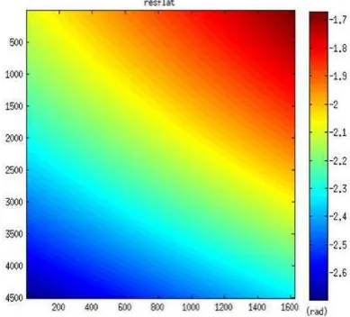
5.3.2 MAI processing results: Two images in Table 1 are processed with the MAI method to obtain the azimuth deformation map of the Yushu earthquake. The azimuth common spectrum filtering is done at first. The Doppler centers of the forward and backward SLC image are located at the 1/4 and 3/4 Doppler spectrum respectively. The spectrum width is half of the original SLC image. The master and slave images have been divided into four segmentations. Then, the normal processing procedure of D-InSAR is conducted. The initial MAI interferogram (Figure 2) is generated by three-differential interference without phase unwrapping. However, as the initial MAI interferogram contains the residual phase caused by the baseline error, the quadratic polynomial fitting method is adopted. The deformation region and low-coherent region (coherence less than 0.8) are masked, and then use the formula (5) to fit the baseline error (Figure 3) in the unmasked area. Finally, the simulated baseline error is subtracted from the initial MAI interferogram and the corrected MAI interferogram (Figure 4) is obtained. Compared with Figure 2, we can see the deformation signals in azimuth direction far away from earthquake field are corrected. Finally, the formula (3) is used to convert it to azimuth deformation map (Figure 5). From Figure 5, we can clearly see that the northern and southern walls on the surface are experiencing opposite movement and the biggest azimuth deformation reaches around 2 m, indicating the earthquake leads to strong motion between the two walls due to earthquake thrusting. Taking the geological structure background of Yushu in consideration, we can judge that the left-lateral strike-slip movement took place in Ganzi – Yushu fault.
No. Acquisition date Track Frame Mode Time interval(d) Perpendicular baseline(m)
1 20100115 487(Ascending) 640-660 FBS
92 650-730 2 20100417 487(Ascending) 640-660 FBS
Table 1. The PALSAR images used
No. Satellite Acquisition date Sensor Waveband Resolution Data type
3 SPOT5 20091105
HRG PAN 2.5m 1A
4 SPOT5 20100415
Figure 1. Co-seismic displacement field in the LOS direction
Figure 2. Original MAI interferogram
Figure 3. Phase induced by the baseline errors
Figure 4. Corrected MAI interferogram
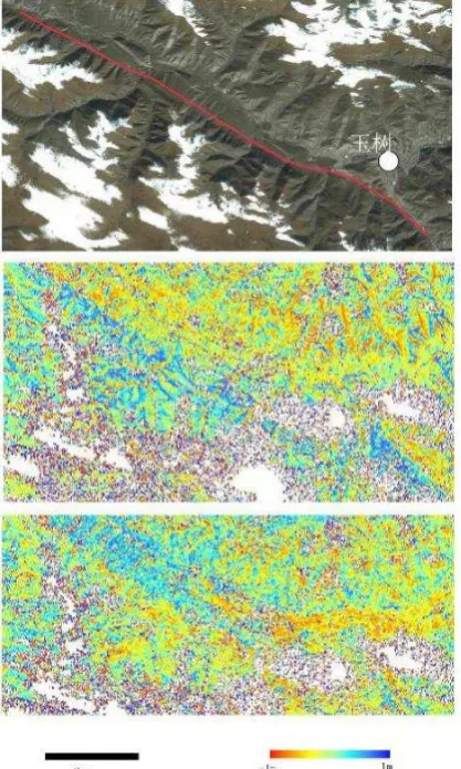
5.3.3 The process of optical image registration: The software platform in this experiment is the COSI- Corr packages developed by the California technical university (Leprince, 2007). The selected satellite images are shown in Table 2. The external data used for correction is SRTM with 90m resolution. The Sinc method used for resampling reduces the main influences on the co-seismic displacement. The sliding window in the experiment is 64 * 64. The co-seismic earthquake displacements along East-West and North-South are obtained, see Figure 6. Through the analysis of co-seismic horizontal displacement field in Figure 6, we can get the distribution of the surface rupture zone and the horizontal co-seismic displacement. The Yushu earthquake is a left-lateral and strike-slip earthquake. The main co-seismic displacement is mainly in horizontal direction while the vertical displacement component is small. According to the co-seismic displacement distribution of Yushu earthquake obtained in this paper, the maximum displacement of this earthquake is no more than 2m, and the surface crack rupture zone, which means it will not have a great impact on the coseismic displacement analysis near the surface rupture zone.
Figure 6. Co-seismic displacement field in the azimuth direction (Top subfigure: the SPOT5 satellite images before the earthquake, the red line is the co-seismic surface rupture zone. Middle subfigure: co-seismic displacement distribution in east-west direction. Bottom subfigure: co-seismic displacement distribution in north–south direction)
Figure 7. SNR map of Co-seismic displacement field (The red line is the co-seismic surface rupture zone.)
6. CONCLUSION
In this paper, the D-InSAR technology, MAI technology, and optical image matching technology are used to obtain the co-seismic displacement field of Yushu earthquake. We find that the co-seismic displacement is obvious in the surface rupture zone. The magnitude and distribution of co-seismic surface displacement reach good agreements with the field investigation results and the characteristics of the fault movement is also in accordance with the actual situation in the earthquake. Thus, the co-seismic displacement field obtained in this paper are reasonable and correct. Additionally, the optical image matching technology is of great application value in terms of surface deformation monitoring
ACKNOWLEDGEMENTS
This research is supported by China Science and Technology Ministry 973 program (2013CB733304, 2013CB733300).
REFERENCES
Alan, V. O., Ronald, W. S., John, R. B., 1989. Discrete-time signal processing. Printice Hall Inc., New Jersey.
Baran, I., Stewart, M., Claessens, S., 2005. A new functional model for determining minimum and maximum detectable deformation gradient resolved by satellite radar interferometry. IEEE Trans. Geosci. Remote Sens., 43(4), pp.675-682.
Bechor, N. B., Zebker, H. A., 2006. Measuring
two‐dimensional movements using a single InSAR
pair. Geophys. Res. Lett., 33(16), doi: 10.1029/2006GL026883.
Gatelli, F., Guamieri, A. M., Parizzi, F., Pasquali, P., Prati, C., Rocca, F. 1994. The wavenumber shift in SAR interferometry. IEEE Trans. Geosci. Remote Sens., 32(4), pp.855-865.
Jung, H. S., Won, J. S., Kim, S. W., 2009. An improvement of the performance of multiple-aperture SAR interferometry (MAI). IEEE Trans. Geosci. Remote Sens., 47(8), pp.2859-2869.
Leprince, S., Barbot, S., Ayoub, F., Avouac, J. P., 2007. Automatic and precise orthorectification, coregistration, and subpixel correlation of satellite images, application to ground deformation measurements. IEEE Trans. Geosci. Remote Sens., 45(6), pp.1529-1558.
Leprince S., 2008. Monitoring Earth Surface Dynamics with Optical Imagery, PhD thesis, California Institute of Technology Pasadena, pp. 7-82,119-173.