VoIP
VoIP
Wireless, P2P and New
Enterprise Voice over IP
Samrat Ganguly
NEC Laboratories America Inc., USA
Sudeept Bhatnagar
AirTight Networks, USA
Copyright c2008 John Wiley & Sons Ltd, The Atrium, Southern Gate, Chichester, West Sussex PO19 8SQ, England
Telephone (+44) 1243 779777
Email (for orders and customer service enquiries): [email protected] Visit our Home Page on www.wiley.com
All Rights Reserved. No part of this publication may be reproduced, stored in a retrieval system or transmitted in any form or by any means, electronic, mechanical, photocopying, recording, scanning or otherwise, except under the terms of the Copyright, Designs and Patents Act 1988 or under the terms of a licence issued by the Copyright Licensing Agency Ltd, 90 Tottenham Court Road, London W1T 4LP, UK, without the permission in writing of the Publisher. Requests to the Publisher should be addressed to the Permissions Department, John Wiley & Sons Ltd, The Atrium, Southern Gate, Chichester, West Sussex PO19 8SQ, England, or emailed to [email protected], or faxed to (+44) 1243 770620.
Designations used by companies to distinguish their products are often claimed as trademarks. All brand names and product names used in this book are trade names, service marks, trademarks or registered trademarks of their respective owners. The Publisher is not associated with any product or vendor mentioned in this book. All trademarks referred to in the text of this publication are the property of their respective owners.
This publication is designed to provide accurate and authoritative information in regard to the subject matter covered. It is sold on the understanding that the Publisher is not engaged in rendering professional services. If professional advice or other expert assistance is required, the services of a competent professional should be sought. Other Wiley Editorial Offices
John Wiley & Sons Inc., 111 River Street, Hoboken, NJ 07030, USA Jossey-Bass, 989 Market Street, San Francisco, CA 94103-1741, USA Wiley-VCH Verlag GmbH, Boschstr. 12, D-69469 Weinheim, Germany
John Wiley & Sons Australia Ltd, 42 McDougall Street, Milton, Queensland 4064, Australia John Wiley & Sons (Asia) Pte Ltd, 2 Clementi Loop #02-01, Jin Xing Distripark, Singapore 129809 John Wiley & Sons Canada Ltd, 6045 Freemont Blvd, Mississauga, ONT, L5R 4J3, Canada
Wiley also publishes its books in a variety of electronic formats. Some content that appears in print may not be available in electronic books.
Library of Congress Cataloging-in-Publication Data Ganguly, Samrat.
VOIP: wireless, P2P and new enterprise voice over IP / Samrat Ganguly, Sudeept Bhatnagar. p. cm.
Includes index.
ISBN 978-0-470-31956-7 (cloth)
1. Internet telephony. I. Bhatnagar, Sudeept. II. Title. TK5105.8865.G36 2008
004.69’5–dc22
2008007367 British Library Cataloguing in Publication Data
A catalogue record for this book is available from the British Library ISBN 978-0-470-31956-7 (HB)
Typeset by Sunrise Setting Ltd.
Preface xvii PART I PRELIMINARIES
1 Introduction to VoIP Networks 3
1.1 Public Switched Telephone Network (PSTN) 3
1.1.1 Switching 4
1.1.2 Routing 5
1.1.3 Connection hierarchy 5
1.1.4 Telephone numbering 6
1.1.5 Signaling 6
1.1.6 Summary 6
1.2 Fundamentals of Internet technology 7
1.2.1 Packetization and packet-switching 7
1.2.2 Addressing 8
1.2.3 Routing and forwarding 8
1.2.4 DNS 10
1.3 Performance issues in the Internet 11
1.3.1 Latency 11
1.3.2 Packet loss 11
vi CONTENTS
1.4 Quality of Service (QoS) guarantees 12
1.4.1 Integrated services 13
1.4.2 Differentiated services 13
1.4.3 Other modifications 14
1.4.3.1 Route pinning 14
1.4.3.2 Packet classification 14
1.4.4 Admission control 15
1.4.5 Status 15
1.5 Summary 15
2 Basics of VoIP 17
2.1 Packetization of voice 17
2.2 Networking technology 18
2.3 Architecture overview 18
2.3.1 Architectural requirements 19
2.3.2 Functional components 21
2.3.2.1 VoIP calling device 21
2.3.2.2 Gateway 21
2.3.2.3 Media server 22
2.3.2.4 Session control server 22
2.3.3 Protocols 22
2.4 Process of making a VoIP call 22
2.5 Deployment issues 23
2.5.1 VoIP quality and performance issues 24
2.5.2 Delay 24
2.5.3 Jitter 25
2.5.4 Packet loss 25
2.5.5 Echo and talk overlap 25
2.5.6 Approaches to maintaining VoIP quality 25
2.5.6.1 Network-level QoS 25
2.5.6.2 VoIP codecs 26
2.6 VoIP applications and services 26
2.6.1 Fax 26
2.6.2 Emergency numbers 26
2.6.3 Roaming 26
2.6.4 Voice over IM 27
2.6.5 Push-to-talk 27
2.6.6 Conferencing 27
2.6.7 Integration with other applications 27
3 VoIP Codecs 29
3.1 Codec design overview 29
3.1.1 VoIP codec design goals 30
3.2 Speech coding techniques 31
3.2.1 Waveform codecs 31
3.2.1.1 Pulse code modulation (PCM) 32
3.2.1.2 Differential PCM (DPCM) 32
3.2.2 Source coding 32
3.2.3 Hybrid coding 33
3.2.4 Adaptive multirate 33
3.3 Narrowband codecs 34
3.3.1 PCM-based G.711 34
3.3.2 ADPCM-based G.721 codecs 34
3.3.3 RPE-based GSM codec 34
3.3.4 Low-delay CELP-based G.728 codec 34
3.3.5 DoD CELP-based G.723.1 codec 35
3.3.6 CS-ACELP-based G.729 codec 35
3.3.7 iLBC 35
3.3.8 Comparison of narrowband codecs 36
3.4 Wideband and multirate codecs 36
3.4.1 Adaptive MultiRate WideBand (AMR-WB) 36
3.4.2 Speex 37
3.5 VoIP softwares 37
3.5.1 Linphone 37
3.5.2 SJphone 37
3.5.3 Skype 38
3.5.4 RAT 38
3.6 Summary 38
4 Performance of Voice Codecs 41
4.1 Factors affecting VoIP quality 41
4.1.1 Effects due to encoding 42
4.1.2 Effects on the decoder 42
4.1.3 Monitoring network conditions 43
4.2 Voice quality assessment 43
4.3 Subjective measures and MOS score 44
4.3.1 Absolute Category Rating (ACR) 44
4.3.2 Degradation Category Rating (DCR) 45
4.3.3 Comparison Category Rating (CCR) 45
viii CONTENTS
4.5 E-Model 46
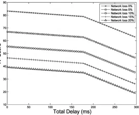
4.5.1 Sensitivity to delay 47
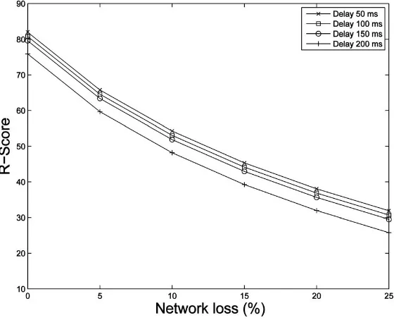
4.6 Sensitivity to loss 48
4.7 Perceptual Evaluation of Speech Quality (PESQ) 50
4.7.1 PESQ analysis for VoIP codecs 50
4.7.2 Cross correlation 53
4.8 Tools for lab testbed setup 53
4.8.1 Network emulator 55
4.9 Voice input/output tools 55
4.9.1 Recording tools 56
4.9.2 Experiment configurations 56
4.10 Summary 57
5 VoIP Protocols 59
5.1 Introduction 59
5.2 Signaling protocols 61
5.2.1 Session Initiation Protocol (SIP) 61
5.2.1.1 Architecture overview 61
5.2.1.2 SIP components 62
5.2.1.3 SIP operation 63
5.2.2 Session Description Protocol (SDP) 64
5.2.3 H.323 64
5.2.3.1 H.323 architecture overview 65
5.2.3.2 H.323 components 65
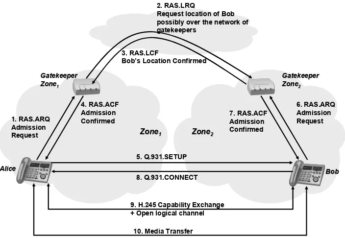
5.2.3.3 H.323 protocols 67
5.2.3.4 H.323 operation 67
5.2.4 Media Gateway Control Protocol (MGCP) 68
5.2.4.1 Components 69
5.2.4.2 Architecture overview 69
5.2.4.3 MGCP operation 69
5.3 Media transport protocols 70
5.3.1 Real-time Transport Protocol (RTP) 70
5.4 Summary 71
PART II VOIP IN OVERLAY NETWORKS
6 Overlay Networks 75
6.1 Internet communication overview 75
6.1.1 Communication operations 76
6.1.3 Internet routing 77
6.1.4 Client–server architecture 77
6.2 Limitations of the Internet 77
6.3 Overlay networks 78
6.3.1 Types of overlay network 79
6.3.1.1 Infrastructure overlays 80
6.3.1.2 P2P overlays 80
6.3.1.3 Design considerations for infrastructure versus P2P
overlays 80
6.3.2 Routing in overlay networks 81
6.4 Applications of overlay networks 82
6.4.1 Content distribution network 82
6.4.2 Overlay multicast 82
6.4.3 Anonymous data delivery 83
6.4.4 Robust routing 84
6.4.5 High bandwidth streaming 85
6.5 Summary 86
7 P2P Technology 87
7.1 P2P communication overview 87
7.1.1 Peer node 88
7.1.2 Node join and leave 88
7.1.3 Bootstrapping 88
7.1.4 Communication process 89
7.2 Classification of P2P networks 89
7.3 Unstructured overlays 90
7.3.1 Centralized resource discovery 91
7.3.2 Controlled flooding 91
7.4 Structured overlays – Distributed Hash Tables (DHTs) 92
7.4.1 Hashing 92
7.4.1.1 Usage in DHT 93
7.4.1.2 Limitations with respect to DHT 93
7.4.1.3 Standard hash functions 94
7.4.2 Consistent hashing 94
7.4.3 Increasing information availability 96
7.5 Types of DHT 96
7.5.1 Chord 96
7.5.2 Koorde 98
7.5.3 CAN 99
x CONTENTS
7.6 Semi-structured overlays 100
7.6.1 FastTrack 101
7.6.2 DHT-based systems 101
7.7 Keyword search using DHT 101
7.8 Summary 102
8 VoIP over Infrastructure Overlays 103
8.1 Introduction 104
8.2 VoIP over overlay – generic architecture 104
8.3 Methods to enhance VoIP quality 105
8.3.1 Path switching 106
8.3.2 Packet buffering 106
8.3.3 Packet replication 107
8.3.4 Coding 109
8.4 Estimating network quality 110
8.4.1 Probe traffic 111
8.4.1.1 Network delay (d) 111
8.4.1.2 Link jitter loss (j) 112
8.4.1.3 Link network loss(n) 112
8.4.1.4 Link cluster factor(c) 113
8.4.2 Estimating path quality 113
8.4.2.1 Path delay 113
8.4.2.2 Path network loss 113
8.4.2.3 Path jitter loss 114
8.4.2.4 Path cluster factor 114
8.5 Route computation 114
8.6 Perceived enhancement of VoIP quality 115
8.7 Summary 116
9 VoIP over P2P 119
9.1 VoIP over P2P overlay – generic architecture 119
9.2 VoIP issues in P2P overlay 120
9.2.1 Architectural issues 121
9.2.2 Network issues 121
9.3 Case study: Skype 122
9.3.1 Skype architecture 123
9.3.2 Skype operation 124
9.3.2.1 Installation and configuration 124
9.3.2.2 Login and authentication 125
9.3.2.4 Call setup and routing 126
9.3.2.5 NAT traversal 126
9.3.2.6 Conferencing 126
9.3.3 Encryption 127
9.3.4 Skype performance 128
9.4 Standardization 130
9.5 Summary 130
PART III VOIP IN WIRELESS NETWORKS
10 IEEE 802.11 Wireless Networks 135
10.1 Network architecture overview 135
10.1.1 Components 135
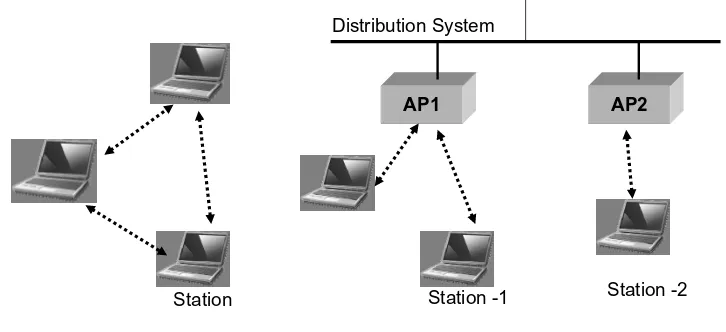
10.1.2 Network configurations 136
10.1.2.1 Ad hoc networks 136
10.1.2.2 Infrastructure networks 136
10.1.2.3 Infrastructure mesh networks 136
10.2 Network access management 137
10.2.1 Association 137
10.2.2 Authentication 138
10.2.3 Mobility 138
10.3 Basic medium access protocol 139
10.3.1 Distributed Coordination Function (DCF) 139
10.3.1.1 Carrier sensing 139
10.3.1.2 Random access 140
10.3.2 Station protocol 140
10.3.3 Hidden terminal problem 141
10.3.4 PCF 142
10.4 Physical layer 142
10.4.1 Spread spectrum techniques in IEEE 802.11b 142
10.4.2 OFDM in IEEE 802.11a 143
10.4.3 MIMO in IEEE 802.11n 143
10.4.4 Modulation and rate control 143
10.5 Network resource management 144
10.5.1 Interference model 144
10.5.2 Channel allocation 145
10.5.3 Power control 146
10.6 IEEE 802.11 standardization overview 147
xii CONTENTS
11 Voice over IEEE 802.11 Wireless Networks 149
11.1 VoIP over WLAN performance problems 149
11.1.1 Channel access delay 150
11.1.2 Interference from simultaneous transmissions 150
11.1.3 External interference 151
11.1.4 Disruption in connectivity 151
11.1.5 Power drain 151
11.2 VoIP capacity 151
11.2.1 Packet aggregation 152
11.2.2 Header compression 153
11.2.3 Interference limited capacity 154
11.2.4 Call admission control 154
11.3 VoIP packet prioritization 155
11.3.1 Downlink prioritization 155
11.3.2 Uplink prioritization using IEEE 802.11e 156 11.3.2.1 Extended distributed channel access (EDCA) 156 11.3.2.2 Hybrid coordination function controlled channel access
(HCCA) 157
11.4 Handoff performance 157
11.4.1 Probing process 157
11.4.2 Scanning using neighbor graph 158
11.4.3 Synchronized scanning 159
11.4.4 Multiscanning using dual radio 159
11.5 Reliable delivery 160
11.6 Client power management 161
11.7 Issues in mesh networks 161
11.7.1 Capacity in mesh networks 162
11.7.2 VoIP call routing 162
11.8 Summary 163
12 IEEE 802.16 WiMAX 165
12.1 WiMAX overview 165
12.2 IEEE 802.11 MAC protocol architecture 166
12.2.1 QoS management 167
12.3 MAC layer framing 168
12.3.1 Aggregation 169
12.3.2 Fragmentation 170
12.3.3 Concatenation 170
12.4 Physical layer 170
12.4.2 OFDMA 171
12.4.3 Slotted allocation 172
12.4.4 Subcarrier mapping 173
12.4.5 OFDMA frame structure 173
12.4.6 OFDMA MIMO 173
12.5 Radio resource management 174
12.5.1 Duplex modes 174
12.5.2 Uplink bandwidth allocation 174
12.6 Competing technologies 175
12.6.1 Comparison with IEEE 802.11 WLAN 175
12.6.2 Comparison with 3G cellular technologies 176
12.6.3 Comparison with LTE and UMB 176
12.7 Summary 176
13 Voice over WiMAX 177
13.1 Introduction 177
13.2 VoIP service delivery over WiMAX network 178
13.2.1 Network entry process 178
13.2.2 Inter-BS handoff process 178
13.2.3 Power-save modes 179
13.3 QoS architecture 179
13.3.1 Serving downlink queues 180
13.3.2 Serving uplink queues 180
13.3.3 QoS provisioning 181
13.4 Call admission control 181
13.5 Uplink QoS control 181
13.5.1 Unsolicited Grant Service (UGS) 182
13.5.2 Real-time Polling Service (rtPS) 182
13.5.3 Non-real-time Polling Service (nrtPS) 182
13.5.4 Best effort service 182
13.6 Enhanced QoS control for VoIP 182
13.6.1 Supporting voice using UGS 183
13.6.2 Supporting VoIP using rtPS 183
13.6.3 Enhanced rtPS for VoIP 184
13.7 MAC enhancement strategies 185
13.7.1 Packet loss probability 185
13.7.2 Packet delay 186
13.7.3 Dynamic adaptation of MPDU size 186
13.7.4 Performance of dynamic adaptation 186
13.8 Comparison with competing technologies 187
xiv CONTENTS
PART IV VOIP IN ENTERPRISE NETWORKS
14 Private Branch Exchange (PBX) 191
14.1 Private Branch Exchange (PBX) 191
14.1.1 Basic PBX functions 192
14.1.2 PBX features 192
14.1.3 IP-PBX 194
14.2 Case study: Asterisk open-source IP-PBX 195
14.2.1 Software architecture 196
14.2.2 Asterisk operation 197
14.2.3 Application gateway interface 200
14.2.4 System requirements 201
14.2.4.1 Summary 203
14.2.5 Asterisk as an application server 204
14.2.6 Desirable features 205
14.3 Summary 206
15 Network Address Translation (NAT) and Firewall 207
15.1 Introduction 208
15.2 NAT fundamentals 208
15.3 Applications of NAT 210
15.3.1 IP address multiplexing 210
15.3.2 Enhanced security 210
15.3.3 Load balancing 211
15.3.4 Failover protection 211
15.3.5 Advantages 211
15.3.6 Drawbacks 211
15.4 Types of NAT 212
15.4.1 Based on type of translation 212
15.4.1.1 Basic NAT 212
15.4.1.2 Address and port translation 212
15.4.2 Based on session binding 212
15.4.2.1 Static 212
15.4.2.2 Dynamic 212
15.4.2.3 Hybrid 212
15.4.3 Based on allowed connections 213
15.4.3.1 Full cone NAT 213
15.4.3.2 Restricted cone NAT 213
15.4.3.3 Port restricted cone NAT 213
15.4.3.4 Symmetric NAT 213
15.5 Firewall 214
15.6 NAT traversal solutions 214
15.6.1 Determining the type of NAT 215
15.6.2 STUN protocol 217
15.6.3 TURN protocol 218
15.6.4 Interactive connectivity establishment 218
15.6.5 Application Layer Gateway (ALG) 218
15.6.6 HTTP tunneling 219
15.7 NAT traversal in H.323 219
15.8 Summary 220
PART V VOIP SERVICE DEPLOYMENT
16 Supporting Services and Applications 223
16.1 Domain Name System (DNS) 223
16.2 ENUM 225
16.3 Network monitoring 225
16.4 Direct Inward Dialing (DID) 226
16.5 Emergency calling (911) 226
16.6 Fax 227
16.7 Summary 228
17 Security and Privacy 231
17.1 Security and privacy issues 232
17.2 Generic issues 232
17.2.1 Malware 232
17.2.2 Spamming 233
17.2.3 Denial of Service (DOS) 233
17.2.4 Access technology weakness 234
17.2.5 Improper implementation 234
17.3 VoIP-related issues 234
17.3.1 Misrepresentation 235
17.3.2 Service theft 235
17.3.3 Eavesdropping 235
17.3.4 Call altering 236
17.3.5 Call hijacking 236
17.3.6 Privacy 236
17.4 Solutions 236
17.4.1 Authentication 237
17.4.2 Message integrity 237
xvi CONTENTS
17.4.4 Data encryption 238
17.4.5 Privacy 239
17.5 Recommendations 239
17.6 Summary 240
18 IP Multimedia Subsystem (IMS) 241
18.1 Introduction 241
18.2 Architecture design goals 242
18.3 IMS advantages 243
18.3.1 End-user experience 243
18.3.2 Enterprise-user experience 243
18.3.3 Benefits for network operators 244
18.3.4 Benefits for service providers 244
18.4 IMS architecture organization 244
18.5 Network Attachment SubSystem (NASS) 246
18.6 Resource Admission Control Subsystem (RACS) 247
18.7 IMS core subsystem 247
18.7.1 Call session control 247
18.7.1.1 Proxy-CSCF 247
18.7.1.2 Serving-CSCF 248
18.7.1.3 Interrogating-CSCF 248
18.7.2 Other functional control entities 248
18.8 IMS QoS management 249
18.9 QoS provisioning approach 249
18.9.1 Guaranteed QoS 249
18.9.2 Relative QoS 249
18.9.3 QoS control mechanism in IMS 249
18.9.3.1 Session control layer 249
18.9.3.2 Transport layer 250
18.9.4 Policy based QoS control 251
18.10 Summary 251
Voice over Internet Protocol (VoIP) is rapidly becoming the technology of choice for voice communication. Several books cover the topics of specific components of VoIP in detail. At a basic level, most of the books in this space describehowVoIP and its various components function.
However, we feel that there is a huge void with respect to information that helps a reader to understandwhycertain features are present,whatis the quantitative impact of the existing design choices, andhow the next generation VoIP should evolve. Knowing how certain components work merely gives a partial view of VoIP and not a complete well-connected picture to the reader to get a whole perspective. In this book, we try our best to bridge this gap in the VoIP information space.
Focus of the book
xviii PREFACE
The book is written in such a manner as to focus on the concepts when describing the components and their interactions, and subsequently highlight the actual system performance under different design choices. Where necessary, we give a brief overview of the specifics of protocols and standards, and will give adequate references at the end of each chapter to guide a user interested in knowing more about the specifics of the topics discussed in the chapter. The book is meant as a guide that provides insights into a wide range of VoIP technologies for a reader intending to understand the technology.
Intended audience
This book is our attempt to disseminate the information that will help the reader to gain a deep understanding of VoIP technology. The content of this book will help an engineer deploying the VoIP technology to acquire substantial knowledge and be able to make informed design choices. This book will help a student who aims to become a VoIP system designer rather than a system deployment technician. A technical reader who is not interested in the nitty-gritty details and needs to have a big picture of the VoIP arena will gain immensely from this book.
Guide to the chapters
The book is organized into five logical sections that describe the impact of diverse technologies on VoIP. The first section introduces the basic components of a VoIP deployment. The next two sections focus on the underlying IP networks (Overlay and Wireless Networks). This focus is intended to provide a general awareness of what each network provides in terms of supporting VoIP. At the same time, the two sections provide a deep understanding of how the network level characteristics affect VoIP and how various network-specific deployment issues are being addressed. The following section on VoIP in Enterprise Networks covers the aspects that are relevant mostly in the VoIP deployment in enterprises. The last section details the relevant auxiliary issues related to the deployment of VoIP as a service.
Each section begins with a summary page that defines the scope and organization of the chapters and introduces the chapter content. Each chapter starts with a brief introduction to help the reader to get a feel of what to expect and ends with a summary to provide a set of simple ‘take away messages’.
PRELIMINARIES
This section deals with the basics of VoIP technology. The chapters in this section give an overview of the various issues and technologies underlying VoIP, ranging from the fundamentals of the Internet to an overview of various aspects of VoIP.
While each chapter in this section contains several topics that can be elaborated significantly more, we refrained from doing so. The goal of this section is to provide a background to the reader and have a framework in which we can place the rest of the book. The section starts with Chapter 1 giving an overview of the fundamental concepts that are required for any telephony network with a reference to the legacy telephone network. The chapter further describes the fundamentals of the current Internet and shows how it can be utilized as a telephony network. Chapter 2 gives an overview of the working of VoIP using a generic architecture. It further provides a glimpse of various issues that any VoIP deployment must tackle.
We delve into the details of voice codecs in Chapter 3. This chapter shows how the analog voice signal is converted into digitized packets for transportation over the Internet. A range of codecs with different capabilities and limitations are highlighted. The actual performance of these codecs in diverse conditions using extensive experimental results is discussed in Chapter 4.
CHAPTER 1
INTRODUCTION TO VoIP NETWORKS
Voice over Internet Protocol (VoIP) has exploded onto the technology scene in the past few years. VoIP is set as the technology that takes our current telephony system referred to as Public Switched Telephone Network (PSTN) to the next generation. Before delving into how VoIP stands to deliver on that promise, we take a brief look at telephony in the PSTN space. Our discussion of PSTN will be more conceptual rather than merely elaborating the components and protocols. The goal is to make the reader understand the philosophy that drove the design of the telephony network and also to lay a foundation to the type of services that would be expected of a full-fledged VoIP network.
1.1 PUBLIC SWITCHED TELEPHONE NETWORK (PSTN)
The era of telephone communication started in 1876, when Alexander Graham Bell enabled the transmission of voice over a wire connecting two phones. Fundamentally, the role of a telephone connection in completing a call is very simple – it needs to connect the microphone of the caller to the hearing piece of the receiver andvice versa. In the beginning of the telephony era, each pair of phones had to have a wire between them in order for them to communicate. There was no shared component between the devices, so while people wanted telephones to communicate, the system was not cost-effective.
1.1.1 Switching
Perhaps the most important development that proved to be a huge step in making a large-scale telephone system viable was the concept of aswitch. The insight that drove the design of a switch was that a dedicated wire between two telephones was essentially being used for a very small fraction of time (unless the parties at the two ends talked all day on the phone); so a way of using that line to serve some other connection while it was idle would serve to reduce the cost of deployment. In particular, the concept ofmultiplexingwas used. The idea was to be able to share the line between multiple telephones on an on-demand basis. Of course, the trade-off was that if two pairs of phones were sharing a single line, only one pair of them could talk at a time. On the other hand, if most of the time only one pair of them intended to communicate, the telephone system could do with only one line rather than two.
Switch Switch
(A) (B)
Alice Bob
Charlie David
Alice Bob
Charlie David
Figure 1.1 Basic functionality of a switch over a four-telephone network. (A) Without a switch six lines are required to connect the four telephones. (B) With a switch, only four lines are required to connect the four telephones to the switch.
In order to implement the concept of multiplexing, there was another problem to be solved. While sharing of a line was definitely a nice insight, the whole wire could not be shared end-to-end since its endpoints are two of the telephones residing at diverse locations. This led to the concept of segmenting the end-to-end wire into smaller pieces and applying the sharing logic onto these pieces. The device that connected these pieces together is a switch. Consider the example shown in Figure 1.1. There are four telephones that need to communicate with each other. In Figure 1.1(A), they are connected directly to each other requiring a total of six lines. In order to reduce the number of lines required, the lines are broken into smaller segments and connected to a switch. as shown in Figure 1.1(B). Now no two phones are directly connected to each other. When Alice wants to talk to Bob, it is now the switch’s responsibility to connect the corresponding two segments together so that together they act as an end-to-end wire. Note that if Alice and Bob are talking, and Charlie wants to talk to Bob, then he cannot at that instant. This is because the line segment from the switch to Bob is already in use for the call from Alice. Thus, Bob’s phone is ‘busy’.
PUBLIC SWITCHED TELEPHONE NETWORK (PSTN) 5
these switches were automated and were able to switch several calls simultaneously. The switches today are electronic and very adept at their task while handling hundreds of calls simultaneously.
1.1.2 Routing
While the concept of switching was an important driver in making the telephony viable in a small geographic region, it was still not enough to spread to larger areas. This is because it was not feasible to connect all the phones in the whole area (state, country, world) to a single switch. This implies the need to have multiple switches corresponding to diverse geographic regions. Of course, this also means that if Alice’s phone is connected to switch A and Bob’s to switch B, then for Alice to call Bob, both switch A and B have to connect their respective segments (to Alice and Bob respectively) as well as to have a connecting segment between them. Conceptually, this requires that each pair of switches should now have a link between them to allow all pairs of telephones to be able to communicate with each other.
Again, the requirement for all switches to connect to all other switches is not scalable. For example, it may be reasonable to have a line connecting switches to two neighboring cities. However, having a line from each switch to every other switch in the world is infeasible.
The alternate strategy extends the concept described earlier. When two phones connected to two physically connected switches need to talk, we required three line segments to be connected together: Alice’s phone to switch A, switch A to switch B, and switch B to Bob’s phone. However, if switch A and switch B are not directly connected, they can still be able to connect through a chain of switches in between. Thus, the larger the distance between Alice and Bob, the larger the number of switches in the path between them. Conceptually, when Alice calls Bob, a whole set of segments and switches are connected in sequence to provide the feel of an end-to-end wire between the two of them. None of these segments can be used for any call while this call is in progress. Essentially, this results in building a dedicatedcircuitbetween Alice and Bob.
The above example uses links which can carry a single call at a time. In practice, the switch-to-switch links (also referred to as exchange-to-exchange links) are replaced byTrunksthat can carry multiple calls simultaneously. This is achieved by methods such as Time Division Multiplexing (TDM) where frames from different calls (containing the encoded voice signals) are multiplexed into a TDM frame that runs over a higher bandwidth. This results in the perception of all the calls proceeding simultaneously. Although the number of calls carried in a trunk is much higher, the bandwidth limitations of the medium limit the number of simultaneous calls possible over a trunk as well. For example, in the USA, a TDM frame contains 24 voice frames implying at most 24 simultaneous calls over the corresponding trunk.
1.1.3 Connection hierarchy
Now any call from a phone connected to Ato a phone connected toB will have to be switched across the country toCfrom where it would be routed back toB. Clearly this type of long link should be avoided as much as possible.
This implies that the switches within each other’s vicinity should be connected to each other rather than to those far apart. A natural extension of this philosophy implies that the switches within cities should be connected to form a network, a few access nodes from this network should connect to other networks in similar states, and the same philosophy extends to countries. Essentially, the political boundaries themselves serve as guidelines to forming networks of switches.
1.1.4 Telephone numbering
Once the hierarchical organization of switches and, in general, exchanges is decided, the final piece of the puzzle is to figure out where a particular phone is located in order to call and how the corresponding call should be routed. Across a large network spread across the globe, knowing all the routes to all the other switches and destinations is not feasible. Thus, each switch can know only a few neighboring switches.
The problem of routing in such a scenario is automatically solved using a proper telephone-numbering system (E.164) that we use today. For example, a telephone number consists of a code, an in-country zone code, and a number describing the local switch/exchange to which the phone is connected. Using the digits of the phone number, the switch at the caller’s end would know to which of the neighboring switches the call should be routed. Following the same procedure end-to-end, a VoIP call is easily established.
1.1.5 Signaling
The call setup procedure described above requires some means of informing all the devices on the end-to-end path of the call to switch the call accordingly. This is achieved using signaling. The current telephony network is based on sophisticated signaling protocol called SS7. It is the most prominent set of protocols in use in the PSTN across the world. Its main use is in setting up and terminating telephone calls. SS7 uses an out-of-band signaling method to set up a call. The speech path of the call is separated from this signaling path to eliminate the chances of an end-user tampering with the setup protocol.
In the PSTN, telephones constantly exchange signals with various network components such as dial tone and dialing a number. SS7 facilitates this type of signaling in the current PSTN. In general, SS7 forms the core of the current PSTN. Along with call establishment and termination, it provides the aforementioned functionalities such as call routing.
1.1.6 Summary
FUNDAMENTALS OF INTERNET TECHNOLOGY 7
It is important to see that while these concepts are described as applicable to PSTN telephony network, in fact, any large-scale telephony network needs to provide these functions. Thus, enabling VoIP over the Internet (which is a large-scale network) also implies that these functions be provided in the Internet. We shall look at how these functions are provided in the Internet both in general and specifically for VoIP.
1.2 FUNDAMENTALS OF INTERNET TECHNOLOGY
What we described above gives the basic idea regarding any telephony system. To enable voice over an IP network such as the Internet,1the capabilities described above need to be provided in the Internet as well. In the following, we describe how these functionalities are provided in the Internet in general.
1.2.1 Packetization and packet-switching
The PSTN is based on the concept of circuit-switching. For any call to go through, a complete end-to-end path is set up comprising of intermediate switches and the dedicated links between them. This sets up a path that is specifically meant for the call prior to the user being able to communicate. Having such a dedicatedcircuitfor a call means that the delay faced by each signal element (carrying the voice) is constant. The components used in the circuit are not available for use until the call terminates.
Each circuit has a capacity to carry some amount of information at each instant. In case of voice, this information is the signal containing the encoded speech. Dedicated circuit for a call results in a wastage of the capacity even if for a small time it is not being used to carry information. This wastage is more prominent in case there are other calls that are not able to connect for want of a segment of this underutilized circuit.
In order to overcome this capacity underutilization a new switching method was conceived. The switching method is calledpacket-switching. The idea is topacketizethe information, i.e. break down the information to be transmitted into smaller chunks called packets and send each packet independently towards the destination. There is no dedicated end-to-end path setup prior to the communication. Each packet containing information to be delivered is sent towards the destination. Each switching elementrouter in the Internet world, would look up the destination address in the packet and send it to the next switching element on the path to the destination. Essentially, different packets belonging to the same end-to-end communication session can take different paths in the network, since there is no circuit for them to follow.
The efficiency gain from circuit switching are from multiplexing at a fine level. Since there are no resources reserved for any end-to-end session at an intermediate router, the router treats all arriving packets as equals. The packets from different sessions are lined up in a queue inside the router which decides where to send the packets one by one. Thus, the router is being used by all calls simultaneously. In the case of VoIP, think of packets containing voice from two different calls sharing the router queue. Also, packet-switching does not lock the router (and a link) for a particular call, implying that packets from a second call can be switched if there are no packets from the first call using the router.
Packet-switching forms the backbone of the Internet. The computers (end-hosts) from the end points of communication are connected using routers. Two computers communicate with each other by packetizing the information to be sent out and then send each packet to the network. They are routed by the network to the destination without establishing an end-to-end connectiona priori.
1.2.2 Addressing
In its present form, the most prevalent addressing scheme in the Internet is based on Internet Protocol version 4 (IPv4). The allocated addresses are called the IP addresses of the respective devices. Each IPv4 address is 32 bits (4 bytes) long. Each address can be written in the dotted decimal notation as A.B.C.D where each of A,B,C,D is a number between 0 and 255 (representing 8 bits).
The addresses are allocated to organizations in sets defined by the common prefix shared by the addresses in the set. In the initial era, the addresses were categorized into classes and allocations were at the granularity of classes. The classes to be allocated for unicast addresses were called Classes A, B and C. Class D defined multicast addresses and Class E addresses were reserved for future use. Each Class A group of addresses was identified by its first 8-bit prefix and hence contained 224 distinct addresses. Similarly Classes B and C had 16- and 24-bit prefixes resulting in address spaces of216and28, respectively. Assigning address spaces at this granularity had an adverse impact as the available address space started depleting very quickly.
To address this concern, a new proposal called Classless Inter-Domain Routing (CIDR) was introduced where the IP addresses were allocated in chunks and identified by their prefixes rather than classes. Thus, a large chunk of addresses that contain all addresses starting with the first 9 bits being 100 001 011 is written as 133.128.0.0/23 where the 23 represents the number of bits that can vary with the prefix 9 bits fixed to 100 001 011 (133.128 represents the decimal value of 1 000 010 110 000 000).
In CIDR addressing, a large chunk of addresses is now given to allocation authorities that can create smaller chunks out of it to allocate to the organizations. For example, a country can be allocated a chunk 133.0.0.0/24. From this chunk, organizations can be given smaller chunks which may depend on their location in the country. This will automatically construct a hierarchy of addresses. The major benefit of such a hierarchy is seen in the routing efficiency.
1.2.3 Routing and forwarding
Routing refers to the process of computing the routes between any two hosts. In a router, the routing process fills out arouting table(or forwarding table), that contains information about which interface the router should forward a packet to so that the packet reaches closer to its destination.
FUNDAMENTALS OF INTERNET TECHNOLOGY 9
can route. Based on the routing policy, the routers will decide the routes for these prefixes. An interesting observation here is that there is implicit hierarchy here. Inside a domain each router knows every other router and would also know the IP addresses of all hosts that are directly connected to this network. However, the external network appears as a single entity in the form of a prefix advertised by a neighbor.
The routing table of each router is computed using the intra-domain and inter-domain routing protocol. Since the Internet is a packet-switched network, the goal is to be able to route any packet to its destination. The routing table is the core that allows this. It contains information about where a router should send a packet, based on its destination IP address. An interesting thing to note is that if the routing table contains an individual entry for each destination IP address in the Internet, there will be232 entries in the routing table. It is very difficult to manage this number of entries in a router. The CIDR-based scheme allows routing tables to be compacted. In this case, the adjacent prefixes could merge into single entry if the corresponding outgoing interfaces for both sets of prefixes is the same. The exact packet header matching algorithm is calledLongest Prefix Match. If there are multiple entries in the routing table that match the destination address of a packet, then the entry which has the maximum number of prefix bits common with the destination IP address is considered the valid matching entry and the packet is forwarded accordingly. For example, for a packet with destination address 133.193.20.24, if there are two entries in the routing table 133.192.0.0/24 and 133.193.0.0/16 (with corresponding forwarding interface), both will match with the packet’s destination address. However, we will use the entry with the latter prefix as it has more prefix bits in common with the destination IP address and forward the packet to the interface corresponding to that entry.
When a packet arrives at a router, the following functions are performed in order:
• Routing Lookup:At the incoming interface, the router needs to determine the output interface for the packet. The router uses the longest prefix match to find the most specific entry in the routing table corresponding to the packet’s destination. A lookup on that entry gives the output interface to which to send the packet. Using the router’s switching fabric, this packet is sent to the corresponding output interface.
• Queue Management:Each output interface has a buffer where it queues all packets forwarded to it by all incoming interfaces. The buffering is required because the output link capacity might not be sufficient to handle the combined traffic from all interfaces. Since the buffer size is finite, the buffer could be full when a new packet arrives. The basic task of the queue management strategy is to determinewhichpacket to drop in such a case. Traditionally, the routers follow adrop-tailpolicy where the incoming packet is dropped if the buffer is full. Note that this is also an implication of packet-switching as the buffer is being shared by packets from diverse connections. Of course, if the buffer is not full, typically the packet will be enqueued at the back of the queue of packets that already reside in the buffer. This is not always the case because there are certainActive Queue Managementmechanisms (such as Random Early Detect – RED) where an incoming packet may be dropped even if the buffer is not full. This is done to indicate to the host that congestion is imminent and it should slow down its traffic rate.
packet in the queue and sends it out on the link. However, from the perspective of VoIP, it may be beneficial to send voice packets, which may be at the back of the queue, prior to the other non-real-time packets such as those belonging to an FTP session.
1.2.4 DNS
Domain Name System (DNS) provides the name to which address the mapping service in the Internet. It is one of the most important services in the Internet. DNS provides the service equivalent of directory lookup.
A DNS query takes a Fully Qualified Domain Name (FQDN) such as a URL and the response contains the current IP address associated with the given FQDN. One of the most important benefits of DNS is that it allows users to remember easy-to-memorize strings rather than IP addresses. For example, it is much easier to remember the website for Wiley as www.wiley.comrather than remembering a set of four numbers representing its IP address.
While from the perspective of the user this FQDN to IP address translation is the single advantage that DNS provides, it has several features from the perspective of the service providers. It allows the servers handling different services in an organization to be identified. We shall see more details of one such usage in Chapter 16. Furthermore, it allows load balancing across servers by returning different mirror server addresses to different user queries. This provides a simple load-balancing solution. As a further extension, the same applies to the use of DNS to provide fault tolerance. If one of the servers providing a service fails, DNS can be used to provide the address of another server seamlessly.
In order to provide this basic service, DNS essentially serves like a distributed database. The Internet namespace is divided into zones with the responsibility of managing the namespace in each zone being delegated to a particular authority. Thus, a zone is essentially a unit of delegation. For example, the authority of the.comzone is delegated to a single authority and that of thewiley.comzone is delegated to another authority. Each zone can have one or more DNS servers which maintain the local namespace database. For example, the name to IP address mapping information forwww.wiley.comwould rest with the DNS server forwiley.comzone.
PERFORMANCE ISSUES IN THE INTERNET 11
1.3 PERFORMANCE ISSUES IN THE INTERNET
While the Internet provides all the features that are required of a telephony network, there are significant other problems that it introduces. It may be tempting to think that with switching, routing, addressing and lookups being provided, VoIP would have no special concerns in the Internet. However, this is not correct. In fact, while the cost of deploying VoIP over the Internet is considerably less (as it is using a shared network), there are significant performance issues that need to be addressed. For VoIP to be a viable alternative to the PSTN, not only should it be cheaper and easier to deploy and maintain, it should provide similar or better call quality so as to motivate an end-user to move to VoIP.
The performance issues that the Internet faces stem from its packet-switching nature. Packets from several flows share the queue at the output interface of a router. The bandwidth that the link connected to that interface is limited. Thus, the resources of the router are shared, resulting in several performance glitches.
1.3.1 Latency
Latency is the total delay that a packet faces while it travels from its source to its destination. There are multiple contributors to the latency. The foremost of these contributors is the physical limit imposed by the speed of light (or electromagnetic wave, depending on the carrier). For example, if a packet (or a signal) has to travel 3000 km over a link, then at speed of light (300 000 km/s), it will take 10 ms to travel. In practice, the signal travelling speed is lower than the speed of light. This delay has to be faced independently of the underlying signal-carrying technology. The second contributor to the latency is thequeueing delay. This is the delay that a packet faces at a router when it is stuck behind other packets waiting for its turn to be transmitted. Note that this delay is not present in the circuit-switched network where there is a dedicated circuit present for the signals for a call. The last source of latency is thetransmission delay. This delay is due to the limited bandwidth of the link on which the packet will be transmitted. Transmission delay calculates the time between the first and last bits of the packet being put on the wire. For example, a 500-byte (4 Kb) packet on a 1 Mbps link will incur a transmission delay of 4 ms because of constraints imposed by the bandwidth of the link.
Delay is an additive quantity. All types of delay incurred at all components add up. Thus, the longer the path, the more the number of routers that a packet will pass through, and the more delayed it is. Furthermore, if traffic at some other source increased so that the packet concerned sees a large queue, it will be delayed further.
1.3.2 Packet loss
There is no concept of loss in the circuit-switched networks. If a connection is established, then until the connection is terminated by the involved parties, all information communicated over the circuit will follow the established circuits and reach the other end. There will be no information loss.
packet-switched networks such as the Internet, special protocols such as TCP have to be designed that identify a packet as being lost (somewhere along the path) and retransmit the packet so that the receiver obtains its content. While increasing packet delays serve as an indication that the queues in some routers are building up, the Internet protocols such as TCP react more drastically to a drop-in packet so as to reduce the load, thereby ameliorating congestion.
While a router’s output interface queue becomes overloaded due to a surge in the traffic from some (potentially other) source , the impact of that surge is seen by our packet under consideration. This type of cross-interaction is possible due to packet switching.
1.3.3 Jitter
Jitter represents the variance in delay seen over a bunch of packets belonging to the same end-to-end connection. Simply put, over the life of a connection, several packets will be exchanged between the source and the destination. It is highly unlikely that each of these packets will face exactly the same queueing delay at all the routers along the path. In fact, given the Internet routing model, it is not guaranteed that all the packets will follow the same path and encounter the same routers.
This variability in the latencies of different packets of a connection is referred to as jitter. There is no jitter in a circuit-switched network. This is because once the end-to-end circuit is set up, there is no one contending with the corresponding connection to grab a share of that circuit.
From the perspective of VoIP, each packet carries some data corresponding to what was spoken. With a large jitter, the words that a packet contains would seem either too cluttered or too spread apart if the packets are played out as and when they arrive. To smooth out this effect, ajitter bufferis used to hold the packets for a while and release them at a smooth rate to the application to play.
1.4 QUALITY OF SERVICE (QoS) GUARANTEES
We have seen that in its native form, the Internet suffers from several problems that can have a significant impact on the performance of real-time applications such as VoIP. In order to counter these scenarios, the Internet Engineering Task Force (IETF), proposed mechanisms where the flows with such real-time requirements would be segregated from the other flows, even while they use the same router equipment. In essence, an application could request a certain amount of network resources along its entire path and its packets can receive preferential treatment from the network. Thus, the packets would be admitted in a special queue to conceal them from the effects of other traffic, and be scheduled for transmission with a higher priority. These requirements have been formalized by two standard mechanisms: Integrated Services and Differentiated Services.
In order to realize both these QoS models, the current Internet architecture needs to be altered, the service model changed, and the router functionalities modified to support the new services. We look first at the architectural changes that are required for both QoS services.
QUALITY OF SERVICE (QoS) GUARANTEES 13
are actually core-stateless where the edge routers of a domain maintain per-flow state and the core routers do not. The major benefit of the stateless architectures comes from eliminating the costly packet classification operation at the core routers. The Integrated Services architecture is stateful whereas Differentiated Services is stateless in this terminology. In both architectures, various router functionalities are altered, and in turn they provide different levels of guarantee as well as having a different level of impact on scalability.
1.4.1 Integrated services
The Integrated Services (Intserv) framework intends to provide strong QoS guarantees to flows. Intserv requires that all routers have a per-flow state. Each router has a separate queue in the output buffer for each flow. A packet is added to the tail of its flow’s queue in the output buffer. This adds another problem for the queue management component: If it has to drop a packet, then it has to take an additional decision about which queue’s packet should be dropped. The scheduler is no longer FIFO because it has to select a queue from which to send the next packet. Since the number of queues is the same as the number of flows, the time complexity of the scheduler depends on the number of flows. The choice of a particular scheduler depends on the type of service provided under the Intserv purview. There are two key services defined under the Intserv framework:Guaranteed and Controlled-load Services.
• Guaranteed Services: Guaranteed service semantics intend to provide per-flow bandwidth and delay guarantees [1]. The routers have to ensure that its packets are never dropped as long as they are compliant with its traffic specification. Additionally, the scheduler employed has to schedule the packets of the flow based on its deadline and rate requirements. However, the complexity of these schedulers is significant and limits the scalability of the framework.
• Controlled-load Services:The controlled-load service intends to isolate a flow from the impact of other flows. The key specification of the controlled-load semantics is to provide an uncongested network view to a flow. The controlled-load service intends to provide a service similar to best-effort service when the routers are unloaded [2]. This type of service is suitable for adaptive real-time applications. VoIP is well-suited for this type of service.
In summary, the Intserv model has strong per-flow service semantics. However, it requires maintenance of per-flow states which renders it unscalable in the number of flows.
1.4.2 Differentiated services
DSCP in an identical fashion irrespective of the flow to which they belong. Since the core routers only have a fixed number of service classes (defined by the number of DSCPs), their scalability becomes independent of the number of flows.
The Diffserv framework has two types of defined service:Assured Service and Premium Service.
• Assured Service:Assured service aims at providing a lightly loaded network view by giving better-than-best effort drop rates to flows [3]. This is attained by implementing preferential dropping where a customer’sout-of-profiletraffic is dropped before his in-profiletraffic. At the ingress router the user’s packets are marked as in-profile or out-of-profile using a meter (or the user could indicate his preference). If a router becomes congested, it will drop the out-of-profile packets first. Thus, the user is assured of a fixed bandwidth (given by its in-profile rate).
• Premium Service:Premium service provides a virtual wire of a desired bandwidth from an ingress point to an egress point [4]. It is implemented using priority queuing to forward the premium packets at the earliest. Note that premium service can provide a bandwidth guarantee to the entire aggregate but since it does not distinguish between packets of individual flows, the delay bounds of individual flows cannot be distinguished, i.e. all flows in an aggregate have the same delay bound irrespective of their requirements.
Thus, the Diffserv framework alleviates the scalability problem of Intserv but can only provide weaker service semantics.
1.4.3 Other modifications
The QoS architectures require changes in the functionalities depending on the type of service model. They also require some additional operations which help in providing these services efficiently. We discuss these operations briefly.
1.4.3.1 Route pinning One of the most fundamental changes required to support the QoS services is the ability to pin a flow to a fixed route. The conventional IP routing allows the routes to change at any time and different packets from the same session can take different paths. These changes could occur based on the underlying traffic changes, for load-balancing or due to topology alterations. To provide bandwidth or delay guarantees to a flow, the network has to be sure that the flow’s path has sufficient resources to meet its requirements. If a flow’s path changes during its lifetime, the new path might not have the desired resources.
Route-pinning techniques make sure that a flow follows its assigned path during its entire lifetime. The most prominent of these strategies are IP source routing, Multi-Protocol Label Switching (MPLS) [5], and Virtual Circuit Switching in ATM networks. In recent years, MPLS has become increasingly popular as a route-pinning and efficient packet-forwarding technology.
SUMMARY 15
the routers need to identifywhichpackets belong to a flow with QoS guarantees andhow these packets need to be treated. This requires a special packet classification functionality which essentially supersedes the routing lookup operation. Packet classification could be done based on multiple fields in the packet header, e.g. the source and destination addresses, protocol number and type of service field.
1.4.4 Admission control
Admission control refers to the process of limiting the number of QoS flows in the system so that their respective QoS guarantees are not violated. Specifically, on receiving a new request for some QoS guarantee, it is the responsibility of the admission control component to test whether there are sufficient resources in terms of bandwidth and buffer at the routers to support the new flow without violating the guarantees of the existing flows.
Of all the services listed above, only assured service could remain meaningful in the absence of admission control. All other services require some sort of admission control. However, the specific type of admission control they require varies, based on their respective characteristics. The admission control methods in the literature could be broadly classified asdeterministicorstatisticalin nature. The deterministic admission control methods take as input the request parameters such as delay and bandwidth and determine whether or not the request could be supported after taking into account the existing reservations and using the knowledge of the scheduler characteristics and buffer availability. Statistical admission control methods on the other hand try to estimate whether or not the request could receive its desired service with some probability.
1.4.5 Status
The two QoS architectures for the Internet have been explicitly defined. However, they still await deployment in the Internet. This can be attributed to a lack of business model for these services along with the fact that any flow’s path will traverse through multiple Internet Service Providers (ISPs) from source to destination. For a QoS guarantee to be given, all these traversed domains have to cooperate at the fine-granularity of per-flow or per-packet. This limitation is another reason for the lack of deployment of these services. Nonetheless, knowledge of these architectures is important as the techniques developed in this context are relevant in VoIP applications.
1.5 SUMMARY
The packet switching used in the Internet provides efficient resource utilization and scalability, but it results in additional performance problems in terms of packets facing excessive delays that could vary significantly from packet to packet and in the worst case the packet could be lost. In order to provide a certain quality of service guarantee to tackle these problems, two major standards have been defined that allow flows preferential treatment at the routers along their path. In order to ensure that the network has sufficient resources to support an additional request, admission control is used to determine whether there are sufficient resources remaining to address a request’s demands.
REFERENCES
1. Shenker, S., Partridge, C. and Guerin, R. Specification of guaranteed quality of service.IETF Request for Comments RFC 2211(1997).
2. Wroclawski, J. Specification of the controlled-load network element service.IETF Request for Comments RFC 2211(1997).
3. Heinanen, J., Baker, F., Weiss, W. and Wroclawski, J. Assured forwarding PHB group.IETF Request for Comments RFC 2597(1999).
4. Jacobson, V., Nichols, K. and Poduri, K. An expedited forwarding PHB. IETF Request for Comments RFC 2598(1999).
CHAPTER 2
BASICS OF VoIP
This chapter gives an overview of the components, their interactions and their need in a VoIP deployment. This serves as a primer for a bird’s eye view of a VoIP system – the desired functionality, the constraints, the components and an overview of how these components are tied together to provide end-to-end voice calls.
This chapter gives the reader the big picture of the VoIP arena. The goal is to have a frame of reference to understand where various components fit in when deploying a VoIP network. After understanding this chapter, the reader will be able to place the content of the more involved chapters in the correct context.
2.1 PACKETIZATION OF VOICE
Before venturing into the generic description of how VoIP works, we need to address a more fundamental question: how is the voice carried across the Internet? Since VoIP carries voice across the Internet, the mode of transport for the voice has to follow that of the underlying network. We saw in Chapter 1 that the Internet breaks the information to be transported across the network to a destination into small packets. The packets are then sent to the destination independently and the destination reassembles the desired information from a collection of packets. Hence, in order for VoIP to work, there is a need to packetize a speaker’s voice. The voice content of a call has to be encoded into one or more packets, the packets should travel across the Internet like any other packets, and the receiver of those packets should be able to decode the voice content from the packets.
Voice was transmitted in the form of analog signals in the old days of PSTN. The signals have to be digitized so that they become amenable to transportation in packets. This is done by sampling the analog waveform at 8000 times per second (Hertz). Then these samples are digitized, encoded using codecs, and multiple such samples are encapsulated into a single packet before being sent towards the destination. More details on the codecs and their performance will be discussed in Chapter 3. For the following discussion, the reader can assume that there is a way of converting voice to packets so that they can be transmitted and routed over the Internet.
2.2 NETWORKING TECHNOLOGY
The Internet contains diverse portions that are built upon different technologies. Like any other data traffic, VoIP also has to operate in these scenarios.
We described in Chapter 1 the basic form of network technology that the Internet uses. The basic form of Internet communication is comprised of packets traversing over routers. The performance issues that this architecture raises are known. However, a wide range of technologies with unique capabilities and limitations are emerging. They have their own impact on VoIP.
Conceptually we can think of the end-to-end path of a call as being comprised of several links. Some of these links are the traditional Internet links that behave in the manner we discussed earlier. The other links can belong to these emerging technologies. These could be the wireless 802.11 links that a VoIP phone can use to access the network or a link behind a NAT/Firewall in an enterprise that limits the type of communication possible. Similarly some portion of the network could be an overlay network resulting in more complicated address lookups than the Internet itself. Subsequent chapters deal with the impact of these technologies in detail.
2.3 ARCHITECTURE OVERVIEW
From an architectural standpoint, the minimum requirement to enable a VoIP call is to have two listening parties, each having a calling device equipped with a VoIP codec and connected over an IP network. However, as VoIP becomes a mainstream service with user demanding services that match and supersede the PSTN-level services, new functional components are being introduced into the VoIP architecture. Consequently, the current VoIP architecture is evolving rapidly by adding new services over VoIP and in addressing various issues specific to the deployment of VoIP over carrier networks, Enterprise LAN, etc.
ARCHITECTURE OVERVIEW 19
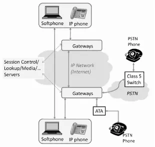
Figure 2.1 VoIP architecture.
2.3.1 Architectural requirements
The basic architectural requirements are derived from the deployment scenarios that enable a flexible communication model. Since the VoIP architecture is meant to enable voice calls over a packet-switched IP network such as the Internet, there are certain types of communication model that it must support. These can be listed as:
• Internet-to-Internet: This type of call includes those that originate on a phone connected to the Internet terminate at a phone connected to the Internet and the entire route remains inside the Internet.
• Internet-to-PSTN:These calls have the caller having a phone connected to the Internet whereas the callee is connected to the PSTN. Here the call traverses through both the PSTN segment and the Internet.
• PSTN-to-Internet:In this setting, the caller is connected to the PSTN whereas the callee has a phone connected to the Internet. Here, also, the call traverses both the PSTN segment and the Internet.
the Internet. This can be done as communication over the Internet is cheaper and typically used for international calls.
• Internet-to-Internet-via-PSTN:Lastly, there can be a case where the call originates and terminates on devices connected to the Internet but a part of the call’s route is over the PSTN. This can be the case when the circuit-switched link through the PSTN reduces the communication delay whereas the end-to-end Internet path may have a higher expected delay.
In order to support these models, the architecture must meet the following functional requirements:
• Address Discovery: When a call is initiated, there is a need to figure out the destination’s location. The destination can be an IP phone for which the address may be an IP address or an InternetUniform Resource Identifier (URI). The address can also be a unique userID as used in many P2P VoIP applications. For supporting the PSTN phones, the destination can be a PSTN phone number. The address discovery service is important in any VoIP architecture for forwarding the call request to the appropriate entity.
• Device Interoperability: A VoIP calling device from different vendors should interoperate by being able to communicate using the same protocol. A VoIP phone from vendorAshould be capable of calling a VoIP phone from VendorB. Following the standards ensures that such diverse devices remain interoperable.
• Interoperability with PSTN phones:In order to enable calling to and from PSTN phones, the architecture must provide functionalities that provide protocol level translation and VoIP data level transcoding. With these functionalities, the call generated from the IP network can be forwarded to and from PSTN network class 5 switches.
• Session-level Control: In different deployment scenarios, various session-level control functionalities become important. Such functionalities include session-level authorization, authentication, user billing, etc.
• Media-level Functionalities:Media-level functionalities refer to services provided to the actual voice over data that is transported over media transport protocols such as RTP. Such functionalities include various media-level processing to enable call mixing for multiparty conferencing, transcoding to enable transport over heterogeneous network links, etc.
• Interoperability among Components: All the functional components of a VoIP architecture should be interoperable by using standard protocols (such as SIP/H.323). This will enable (a) multivendor equipments to inter-operate; and (b) multiple VoIP service providers to coordinate in carrying each others’ VoIP traffic.
ARCHITECTURE OVERVIEW 21
The next step in understanding the VoIP architecture is to define the minimum set of functional components and protocols that are required to meet the above requirements.
2.3.2 Functional components
Having defined an abstract architecture for VoIP, we now look at some of the functional components that this architecture needs.
2.3.2.1 VoIP calling device These are the devices that an end-user requires to initiate or receive a call. These include:
• IP Telephone:An IP telephone is a device which can directly be connected to the Internet. It has some in-built software that allows it to communicate with other VoIP devices. Along with other features, this software can provide the functionality to set up a call and the protocols necessary to transport the voice packets. An IP phone can connect to a network using a standard RJ-45 Ethernet connector or it can be a wi-fi VoIP phone that can connect to the Internet using the IEEE 802.11 wireless networks.
• Softphone: A softphone is a telephone implemented entirely in software. The softphone runs on a computer or a PDA and a user can use it to dial any number such as in traditional telephony. VoIP does not distinguish between a softphone and a hardphone. In fact, this allows the user to have no additional telephone equipment and makes computer-to-computer or computer-to-PSTN calls possible.
• Analog Telephone:An analog telephone is one that is traditionally used to connect to the PSTN.
• Analog Telephone Adapter (ATA):If a user wishes to use a legacy analog telephone to connect to the Internet, an ATA can be used. A stand-alone ATA contains the logic to communicate with the service provider over the Internet and to translate the communication to and from the telephone.
Any VoIP-capable calling device must contain the VoIP codec whose purpose is to encode digitized samples of voice and make them amenable to transmission as packets. More details on codecs are available in subsequent chapters.
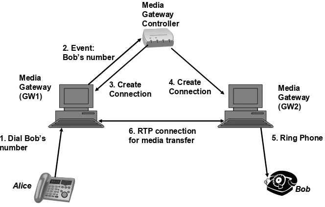
2.3.2.2 Gateway Perhaps the most important component to establish the viability of a VoIP system is a gateway. The task of a gateway is to sit at the border of two different types of network and help them communicate. In the case of VoIP, these two networks can be the Internet and the PSTN. Typically, a gateway consists of two main components: (a) a gateway controller; (b) a media gateway.