Coverage Enhancement through
Two-hop Relaying in Cellular
Radio Systems
Coverage Enhancement through
Two-hop Relaying in Cellular
Radio Systems
Van Sreng
[email protected] Supervised by
Prof. David D. Falconer Prof. Halim Yanikomeroglu
Outline
MOTIVATION
BACKGROUND
SIMULATION SCENARIOS:
Relay Node/Path Selection Schemes Channel Selection Schemes
SIMULATION MODEL
SIMULATION RESULTS
CONCLUDING REMARKS
Motivation
Current problems exist in Cellular systems:
Poor coverage due to a lack of LOS (Line of Sight) or
severe fading.
95% - 99% area coverage goal set by service providers
is impossible to meet.
Some solutions exist today:
Use of repeaters (installation planning & costs)
Sectorized cells (more costs)
Smart antennas (costs & long deployment period)
Our proposed solution:
Background
Relaying began in Packet Radio Systems
(infrastructureless), starting with the DARPA (Defense
Advanced Research Projects Agency) project.
Characteristics of a PR network include:
Store-and-forward form of packet forwarding Low bandwidth
Shared radio channel
Communications are mainly in a broadcast mode Is highly dynamic because links come and go Requires high connectivity establishment
Radios have low transmission range
Inherent Problems:
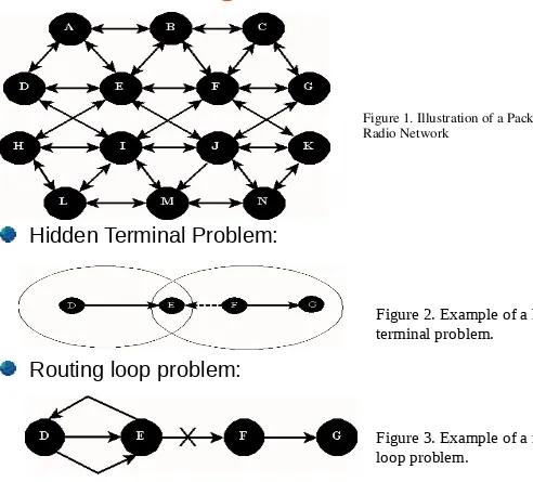
Background (cont.)
Hidden Terminal Problem:
[image:5.720.85.577.43.488.2]Routing loop problem:
Figure 2. Example of a hidden terminal problem.
Figure 3. Example of a routing
Background (cont.)
Routing objectives:
Minimize number of hops Minimize interference
Avoid routing loop and hidden terminal problems
Coping with the topology change in order to have a reliable communication.
Today’s relaying networks have become known as Ad-hoc
Networks (still infrastructureless); purpose is now geared
towards commercial applications such as:
Conferences/Meetings/Lectures (slides/files sharing) Workshops
Background (cont.)
Relaying in Cellular Networks:
Advantages:
There is a central controller and communications must go through it.
Packets forwarding requires less number of hops.
Routing is simplified since links are only established as needed.
Provides a receiver capture effect, through power control & separate channels, that will result in a desired signal
improvement.
Disadvantages:
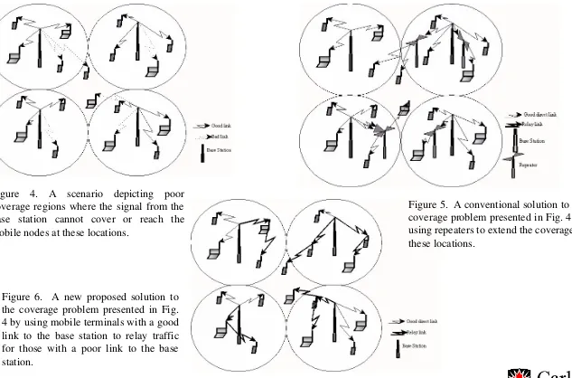
Background (cont.)
Figure 4. A scenario depicting poor coverage regions where the signal from the base station cannot cover or reach the mobile nodes at these locations.
Figure 5. A conventional solution to the coverage problem presented in Fig. 4 by using repeaters to extend the coverage to these locations.
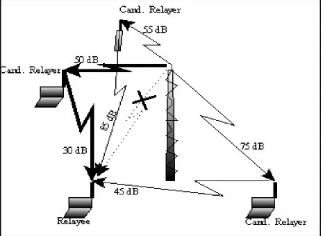
[image:8.720.35.668.86.504.2]Simulation Scenarios
Relay Node/Path Selection Schemes (Two-hop relaying):
Let
PLn1 & PLn2
be
the path-losses (based on distance attenuation and
lognormal shadowing) associated with the first and the second hop,
respectively, along the
n
throute, and
R
the set of potential relay nodes,
then for:
Smart Selection Scheme, the selected path, ps, is:
(1)
Semi-Smart Selection Scheme, the selected path, ps, is:
(2)
Simple Selection Scheme, the selected path, ps, is:
(3)
})
(max{
min
arg
n1, n2n all
s
PL
PL
p
t n n n alls
PL
C
I
p
arg
min
{
2},
(
/
)
1
)
(
rand
R
Simulation Scenarios
Simulation Scenarios (cont.)
Simulation Scenarios (cont.)
Channel Selection Schemes (adjacent-cell channel reuse in a TDMA based system) for downlink scenario only:
Let (C/I)i,c be the carrier-to-interference ratio received at the relayed node i, on
channel c, and B the set of all base stations that use channel c. Then,
, where Gji is the path-loss coefficient between the relayed node (4)
i and the relay node j, and Pj,c is the transmitted power of the relay node j. Then, for:
Smart Channel Selection, the channel selected, ls, is:
(5)
where Inew is the interference due to the candidate relay link, Iold is the interference due to the
existing links, N is thermal noise, is the minimum threshold required, K is the set of reusable channels and L the set of all channels available in the adjacent cells.
Semi-Smart Channel Selection, the channel selected, ls, is:
(6)
Simple Channel Selection, the channel selected, ls, is:
(7)
B
k ki kc c j ji c i P G P G I C ) ( ) ( ) / ( , , , , , )) /( ( ), ) / (( max
arg C I , C I I N , K L
l ic new old jc t
K c all
s
) ) / (( max
arg i,c
L c all
s C I
l ) ( rand L
ls
t
Simulation Scenarios (cont.)
Channel Reusability Check (Downlink scenario):
Let G, where G = {Gij}, be the link gain (path-loss coefficient) matrix of all the
co-channel links associated with the channel of interest, then with q mobile
nodes involved G will be a q x q matrix. Then:
Z = {Zij}, where (8)
rewriting the condition in (5) using the relationship given in (4), and through manipulation and using matrix notation we obtain: (9)
A maximum achievable (C/I), is then determined from the largest real eigenvalue of this Z matrix according to the following:
= 1 / ( where is the largest real eigenvalue of this matrix. If t, then there exists a positive power vector such that all the links
belonging to the co-channel set of the channel under question can be active .
) 1
( PZP
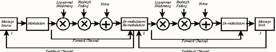
Simulation Model
Environment & Parameter assumptions:
Urban environment with pass-loss exponent: n = 4 Lognormal shadowing: = 10 dB
Flat Rayleigh fading
Omnidirectional antennas for both the base station & subscriber terminal
RF Carrier = 2.5 GHz, BW = 2 MHz Thermal Noise: Noise Figure = 8 dB Max. number of hops = 2
Max. number of relayed nodes = 7
Simulation area: 6x6 square cells (wrap-around edges), 4-cell clusters, cell size varies from 400x400 m to 2x2 km
Subscribers uniformly distributed
Simulation Model (cont.)
Model Assumptions:
Same path-loss model for both: between base station to subscriber and between one subscriber to another.
Number of channels available per cell increases linearly with cell density (focusing on coverage aspects, rather than
channel capacity aspects, of performance).
Doppler effects ignored (reasonable with low mobility). Adjacent-channel interference ignored.
When handing off from a relay node, a mobile node is forced to link up with the base station first if this link is good.
Due to large bandwidth and high noise figure assumption, digital form of relaying is assumed so that no noise is
propagated.
Coverage is defined as Pr[SINR Threshold] 95%.
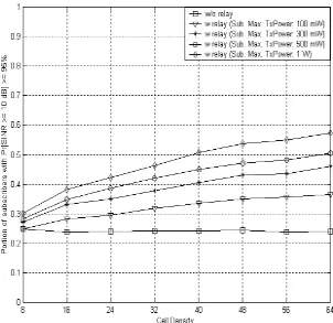
Figure 9. User Coverage v.s Cell Density (for 2x2 km cell size, No Power Control, Smart Relayer Selection, Semi-Smart Channel Selection).
[image:16.720.29.359.134.422.2]Simulation Results
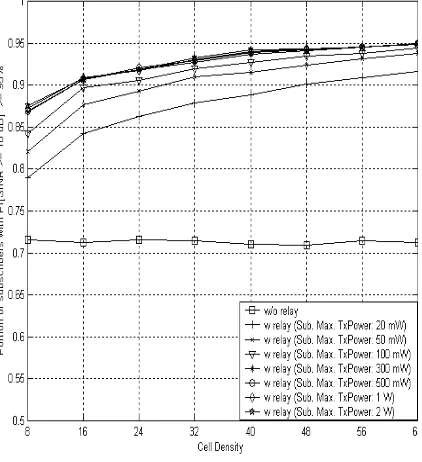
Figure 10. User Coverage v.s Cell Density (for 2x2 km cell size, Power Control, Smart Relayer
Selection, Semi-Smart Channel Selection).
Simulation Results (cont.)
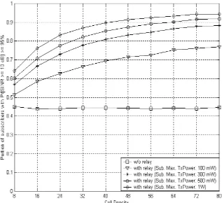
[image:17.720.29.345.107.396.2]Figure 11. User Coverage v.s Cell Density (for 1x1 km cell size, No Power Control, Smart Relayer Selection, Semi-Smart Channel Selection).
Figure 12. User Coverage v.s Cell Density (for 1x1 km cell size, Power Control, Smart Relayer
Simulation Results
(cont.)
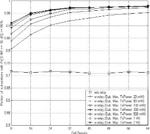
Figure 13. User Coverage v.s Cell Density (for 400x400 m cell size, No Power Control, Smart Relayer Selection, Semi-Smart Channel Selection).
Figure 14. User Coverage v.s Cell Density (for 400x400 m cell size, Power Control, Smart Relayer Selection, Semi-Smart Channel Selection).
[image:18.720.29.340.127.396.2]Simulation Results
(cont.)
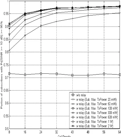
[image:19.720.240.471.115.359.2]Figure 17. User Coverage v.s Cell Density (for 400x400 m cell size, Power Control, Smart Relayer Selection, Semi-Smart Channel Selection).
Figure 16. User Coverage v.s Cell Density (for 400x400 m cell size, Power Control, Semi-Smart Relayer Selection, Semi-Smart Channel Selection).
Impact of
Relay Node/Path Selection on Coverage:
[image:19.720.18.220.121.354.2]Simulation Results (cont.)
[image:20.720.246.470.125.356.2]Figure 20. User Coverage v.s Cell Density (for 400x400 m cell size, Power Control, Smart Relayer Selection, Smart Channel Selection).
Figure 19. User Coverage v.s Cell Density (for 400x400 m cell size, Power Control, Smart Relayer Selection, Semi-Smart Channel Selection).
Impact of
Channel Selection on Coverage:
[image:20.720.19.230.127.358.2]Simulation Results (cont.)
Worst Case Performance v.s Best Case Performance :
[image:21.720.382.690.129.409.2]Figure 22. User Coverage v.s Cell Density (for 400x400 m cell size, Power Control, Smart Relayer Figure 21. User Coverage v.s Cell Density (for
Concluding Remarks
Relaying can have a significant improvement on coverage provided a good relay node selection is implemented.
Even without extra channels reserved for relaying, with power control and a good relay node selection this improvement is quite insensitive to the channel selection schemes. Hence, perhaps it is more advantageous to opt for the simple scheme while
sacrificing a slight performance return.
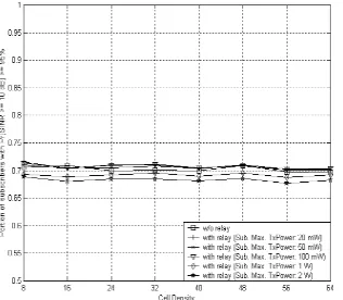
Relaying helps lower power consumption.
Concluding Remarks (Cont.)
Relaying in cellular systems is opportunity driven, thus:
The unlicensed band spectrum (902 MHz - 928 MHz, 2.4 GHz - 2.483 GHz, 5.725 - 5.85 GHz) seems very attractive for using it for relaying purposes.
Since a good LOS must be obtained via relaying, higher throughput can be delivered to individual relayed nodes,
through adaptive modulation, without requiring the transmitter to use greater power.
Pending question: how much relaying is allowed?
i.e., since long relay sessions will drain the battery of the relay node’s terminal, should relaying be enforced only when
Future Study
Performance analysis of multihop relaying in cellular
systems.
Propagation & channel characterization study between low
height transmitting terminals.
Effectiveness of using directional antennas at the
subscriber terminals.
Effectiveness of Adaptive Modulation to increase individual
node’s throughput.
Market survey on users’ willingness to cooperate in this
References
[1] E. H. Drucker, “Development and Application of a Cellular Repeater,” IEEE Vehicular
Technology Conf., pp. 321-325, June 1988.
[2] E. M. Royer and C. Toh, “A Review of Current Routing Protocols for Ad Hoc Mobile Wireless Networks,” IEEE Personal Communications, pp. 46-55, April 1999.
[3] G. N. Aggelou and R. Tafazolli, “On the Relaying Capability of Next Generation GSM Cellular Networks,” IEEE Personal Communications, pp. 40-47, February 2001.
[4] T. J. Harold and A. R. Nix, “Intelligent Relaying for future Personal Communications Systems,” Centre for Communications Research, University of Bristol, 2000.
[5] H. Wu, C. Qiao, and O. Tonguz, “Performance Analysis of iCAR (Integrated Cellular and Ad-hoc Relay System),” to appear in International Conf. for Communications, 2001.