KEIJO PENTTILÄ
QUALITY IMPROVEMENT OF PLASMA SPRAYED CHROMIA
COATINGS BY IN SITU DRY ICE PROCESSING
Master of Science thesis
Examiners: prof. Petri Vuoristo, M.Sc. Jarkko Kiilakoski
Examiner and topic approved by the Faculty Council of the Faculty of Engineering sciences
ABSTRACT
KEIJO PENTTILÄ: Quality improvement of plasma sprayed chromia coatings by in situ dry ice processing
Tampere University of Technology
Master of Science Thesis,107 pages, 10 Appendix pages May 2017
Master’s Degree Programme in Materials Technology Major: Surface Engineering and Ceramic Materials
Examiner: Professor Petri Vuoristo, M.Sc. Jarkko Kiilakoski
Keywords: thermal spraying, plasma spraying, chromium oxide, dry ice blasting Atmospheric plasma spraying is a commonly used process to deposit ceramic coatings for applications of wear and corrosion protection. Feedstock materials include for exam-ple aluminium oxide, titanium oxide and chromium oxide. Plasma sprayed chromium oxide coatings are widely used in for example anilox rolls, pump seals and wear rings for their good surface quality, high hardness and wear resistance.
Chromium oxide is however challenging to spray due to its high melting point, low ther-mal conductivity and tendency to vaporize in high temperatures. The vaporization of chromium oxide during spraying creates extremely fine dust particles, which gather on the workpiece and are trapped inside the coating layers reducing the cohesion and me-chanical properties of the coating.
Dry ice blasting has been used in the field to improve the quality of chromium oxide and many other plasma sprayed coatings by keeping the surfaces clean and helping with ther-mal management. The use of dry ice blasting during spraying was investigated by plasma spraying chromium oxide coating at TUT with two different commercial dry ice blasters attached to the spraying robot. Several parameters were tested and temperature monitor-ing was implemented. Metallographic specimens were prepared and analysed by SEM. Hardness, adhesion, gas permeability and wear tests were also conducted.
It was found that dry ice blasting modifies the temperature history of the substrate and coating dramatically having unexpected effects. Excessive cooling lessened splat to splat bonding lowering cohesion and wear resistance but adjusting the spraying parameters hotter eliminated some of the adverse effects.There were also great differences in differ-ent blaster models related to the size of the particles exiting the nozzle. While the other blaster sprayed only small dry ice dust that mainly cooled the substrate, the other sprayed larger pellets with greater kinetic energy having a much more positive effect on coating cohesion increasing wear resistance compared to non-dry ice blasted samples.
TIIVISTELMÄ
KEIJO PENTTILÄ: Plasmaruiskutettujen kromioksidipinnoitteiden laadunparan-nus kuivajääpuhalluksella
Tampereen teknillinen yliopisto Diplomityö, 107 sivua, 10 liitesivua Toukokuu 2017
Materiaalitekniikan diplomi-insinöörin tutkinto-ohjelma Pääaine: Pinnoitustekniikka ja keraamimateriaalit
Tarkastaja: professori Petri Vuoristo, dipl.ins. Jarkko Kiilakoski
Avainsanat: terminen ruiskutus, plasma ruiskutus, kromioksidi, kuivajääpuhallus Plasmaruiskutusta käytetään keraamisten pinnoitteiden valmistamiseen erityisesti kulu-tus- ja korroosiokestävyyttä vaativiin käyttökohteisiin. Lähtöaineena käytetään esimer-kiksi alumiinioksidia, titaanioksidia ja kromioksidia. Plasmaruiskutettuja kromioksidi-pinnoitteita käytetään laajasti esimerkiksi painokoneiden teloissa, tiivisteissä ja kulutus-renkaissa niiden hyvän pinnanlaadun, korkean kovuuden ja kulutuskestävyyden vuoksi. Kromioksidi on kuitenkin haastava materiaali ruiskuttaa sen korkean sulamislämpötilan ja matalan lämmönjohtavuuden vuoksi. Kromioksidi myös höyrystyy helposti korkeissa lämpötiloissa, joka johtaa hienon kromioksidipölyn muodostumiseen. Muodostuva kro-mioksidipöly jää helposti pinnoitekerrosten väliin heikentäen pinnoitteen koheesiota ja mekaanisia ominaisuuksia.
Alalla on käytetty kuivajääpuhallusta termisen ruiskutuksen yhteydessä kromioksidi- ja muiden plasmaruiskutettujen pinnoitteiden laadunparannukseen. Kuivajääpuhallus pitää työkappaleen pinnan puhtaana ja auttaa lämmönhallinnassa. Kuivajääpuhalluksen käyt-töä plasmaruiskutuksen aikana tutkittiin TTY:llä ruiskuttamalla kromioksidia kahden eri-laisen kuivajääpuhaltimen avustamana, siten että kuivajääpuhaltimen suutin oli kiinni-tetty ruiskutusrobottiin plasmaruiskun kanssa. Useita eri parametreja kokeiltiin ja työkap-paleen lämpötilaa valvottiin. Pinnoitteista valmistettiin metallografiset näytteet, jotka analysoitiin elektronimikroskoopilla. Näytteille tehtiin myös kovuus-, adheesio-, kaasun-läpäisy- ja kulutuskokeet.
Näytteistä havaittiin, että kuivajääpuhalluksella oli odottamattomia seurauksia sen vai-kuttaessa huomattavasti substraatin ja pinnoitteen lämpötilahistoriaan. Liiallinen jäähdy-tys heikensi pinnoitteen koheesiota ja kulutuskestävyyttä, mutta parametrien säätämisellä kuumemmaksi päästiin eroon joistain haitallisista vaikutuksista. Kuivajääpuhaltimien suuttimesta ulos tulevien kuivajääpartikkelien koossa oli myös huomattavia eroja eri pu-hallinmallien välillä. Toinen puhaltimista suihkutti vain hienoa kuivajääpölyä, jolla vai-kutti olevan lähinnä jäähdyttävä vaikutus. Kun taas toinen ruisvai-kutti isompia kuivajääpar-tikkeleita, joiden suuremmalla kineettisellä energialla vaikutti olevan positiivisempi vai-kutus pinnoitteen koheesioon parantaen kulutuskestävyyttä verrattuna ilmajäähdytettyyn näytteeseen
PREFACE
The long and arduous process that would culminate in this thesis started in the summer of 2015 and was eventually brought to an end at springtime 2017. This thesis was written in the Surface Engineering group at the Laboratory of Materials Science. I would like to thank Professor Petri Vuoristo and M.Sc. Jarkko Kiilakoski for their recurring guidance during the research and writing process, as well as senior laboratory technician Mikko Kylmälahti for his assistance.
I am also grateful of the pleasant working environment provided by the Surface Engi-neering group for all these years before and during the writing of this thesis. My final thanks go to Niina for her continued understanding and words of encouragement.
Tampere, 19.4.2017
CONTENTS
1. INTRODUCTION ... 8
2. THERMAL SPRAYING ... 9
2.1 Atmospheric plasma spraying ... 11
2.2 High velocity oxy-fuel spraying ... 16
3. THERMAL SPRAYED OXIDE COATINGS ... 19
3.1 Chromium oxide coatings ... 22
4. SPRAYABILITY OF CHROMIUM OXIDE ... 26
4.1 Plasma spraying of chromium oxide ... 26
4.2 HVOF spraying of chromium oxide ... 27
4.3 Vaporization of chromium oxide ... 29
4.4 Health effects of hexavalent chromium ... 35
5. AUXILIARY SYSTEMS FOR COOLING AND CLEANING ... 37
5.1 Compressed air cooling ... 40
5.2 Liquid nitrogen cooling ... 41
5.3 Carbon dioxide cooling ... 42
5.3.1 CO2-snow blasting ... 42
5.3.2 Dry ice blasting ... 44
6. EXPERIMENTAL STUDY ... 52
6.1 Plasma spraying with dry ice blasting ... 52
6.2 Specimen preparation ... 57
6.3 Research methods ... 57
6.3.1 Dry ice particle measurements ... 57
6.3.2 Surface temperature monitoring... 58
6.3.3 Microstructural characterization ... 58
6.3.4 Hardness testing and surface roughness measurements ... 58
6.3.5 Wear testing ... 59
6.3.6 Adhesion tests ... 61
6.3.7 Gas permeability measurements ... 62
7. RESULTS ... 63
7.1 Dry ice particle in-flight properties ... 63
7.2 Surface temperature... 65
7.3 Microstructure ... 69
7.4 Thickness & surface roughness ... 75
7.5 Hardness ... 77
7.6 Abrasion resistance ... 81
7.7 Erosion resistance ... 83
7.8 Cavitation resistance ... 85
7.10 Gas permeability ... 91
8. DISCUSSION ... 92
9. CONCLUSIONS ... 97
REFERENCES ... 98
LIST OF SYMBOLS AND ABBREVIATIONS
316L SAE 316L grade austenitic stainless steelAg2O silver(I) oxide
Al2O3 aluminium(III) oxide or alumina
APS Atmospheric Plasma Spraying
Ar argon
BSE Back-Scattered Electrons, a type of signal in electron microscopy
C2H2 acetylene
C2H4 ethylene
C3H6 propene
C3H8 propane
CaF2 calcium fluoride
CeO2 cerium(IV) oxide
Co cobalt, a binder used in hardmetals
CO2 carbon dioxide
CoCr cobalt-chrome, a binder used in hardmetals
cp specific heat capacity
CAPS Controlled Atmosphere Plasma Spraying Cr2O3 chromium(III) oxide or chromia
Cr3C2 chromium carbide, a carbide used in hardmetals CrO2(OH)2 hexavalent chromium oxyhydroxide
CrO3 hexavalent chromium
DE Deposition Efficiency
F4-MB plasma torch manufactured by Oerlikon Metco
Fe3Al iron aluminide, an intermetallic phase of iron and aluminium FeAl iron aluminide, an intermetallic phase of iron and aluminium
H2 hydrogen
H2SO4 sulfuric acid
He helium
Hu net calorific value, energy released during fuel gas combustion
HV Vickers hardness value
HVAF High Velocity Air Fuel spraying HVOF High Velocity Oxy-Fuel spraying
MgO magnesium oxide
Mohs Mohs scale of mineral hardness
MoO3 molybdenum trioxide
N2 nitrogen
NaOH sodium hydroxide
NiCr nickel-chromium, a binder used in hardmetals
NiCrAlY nickel-chromium-aluminium-yttrium, commonly used as bond coats NiCrBSi nickel-based super alloy
NIOSH The National Institute for Occupational Safety and Health (USA) OSHA Occupational Safety and Health Administration (USA)
p(H2O) partial pressure of water vapour p(O2) partial pressure of oxygen PEL Permissible Exposure Limit PSZ Partially Stabilized Zirconia
REL Recommended Exposure Limit
RoHS Restriction of Hazardous Substances, Directive 2002/95/EC
RPM Revolutions Per Minute
SE Secondary Electrons, a type of signal in electron microscopy SEM Scanning Electron Microscope
SiC silicon carbide
SiO2 silicon dioxide or silica slpm standard litre per minute SOFC Solid Oxide Fuel Cell stddev standard deviation
TiO2 titanium dioxide or titania
Tm melting temperature
WC tungsten carbide, a carbide used in hardmetals
VPS Vacuum Plasma Spraying
wt% weight percent
XPS X-ray photoelectron spectroscopy Y2O3 yttrium(III) oxide or yttria
YSZ Yttria-Stabilized Zirconia
1. INTRODUCTION
Ceramic coatings have a wide range of applications in the industry ranging from wear and corrosion protection to thermal protection and electrical insulation. Chromium oxide is a high hardness ceramic material and it is widely used in coatings for its excellent tribological properties such as high wear resistance. Atmospheric plasma spraying is often the preferred technology for applying chromium oxide coatings due to its extremely high flame temperature capable of readily melting ceramic materials [1]. Chromium oxide is however quite volatile at high temperatures vaporizing easily and creating fine dust that may cause problems when trapped inside the coating structure. In relatively recent studies [64]-[75], simultaneous dry ice processing has been found to improve the quality of plasma sprayed coatings across multiple different materials, including chromium oxide. As a result, the microstructure and mechanical properties of the coatings were noticeably improved according to the studies.
This thesis builds on past work done in the field with dry ice processing of plasma sprayed coatings and aims to assess further the viability of auxiliary dry ice blasting as a technol-ogy for improving the quality of plasma sprayed chromium oxide coatings. A dry ice blaster was implemented in a plasma spraying process to provide cooling and to clean the workpiece simultaneously while spraying. Several parameter combinations were tested with the setup and after careful optimization, some benefits of the dry ice process were eventually realized. High-speed imaging and thermal monitoring of the substrate was uti-lized to find the optimal processing parameters. The effect of dry ice blasting on the mi-crostructure was evaluated using optical and electron microscopy. Additionally the coat-ings were tested for surface quality, hardness, adhesion, permeability and wear.
Chapter 2 begins with the basics of thermal spraying further explaining plasma and HVOF spraying technologies. Chapter 3 presents the most commonly used ceramic coating ma-terials and introduces the reader to chromium oxide as a coating material. Chapter 4 delves deeper into the sprayability of chromium oxide and its challenges also covering the health issues related to its use. Chapter 5 explores the possibilities of auxiliary cooling in thermal spraying processes and the different technologies available. Chapters 6-9 cover the experimental portion of this thesis along with the results, discussion and conclusions.
2. THERMAL SPRAYING
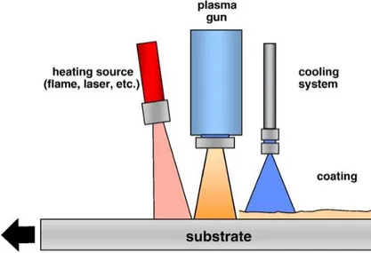
Thermal spraying is a widely used thermomechanical coating process used to deposit a multitude of different materials as coatings on various substrates materials. Most metals and metallic alloys can be thermal sprayed as well as ceramics, composite and cermet materials. Coating thicknesses are typically in the range of 50-500 µm but with certain applications thicker or thinner coatings may be applied [1]. In thermal spraying the raw material is introduced into a heat source as a powder, wire, rod or as a liquid suspension. The molten or semi-molten droplets are then propelled towards the substrate by a gas stream. Upon contact, the droplets deform and conform to the surface forming what are referred to as splats. The individual splats solidify and form the coating. An exception to the above description is the cold spray process, which does not take advantage of heat but relies on high particle velocities (up to 1100 m/s) to deform the powder particles plas-tically instead of melting them. Naturally, only easily deformable metals and alloys can be deposited with the method. The thermal spray process is illustrated in Figure 1.
Figure 1. Typical thermal spray process and coating structure. [1] (p. 33)
Thermal spray processes are commonly classified by heat source, which include electric arc, plasma arc and combustion. In electric arc spraying two metallic wires are fed at an angle towards each other and an electric arc is struck between them. The arc melts the wires as they are fed closer to one another. An atomizing gas coming from behind the
electric arc atomizes the melting material into droplets and propels them towards the sub-strate. Feedstock is limited to wires, which are made of a malleable conductive metal, but cored wires containing even cermets are available expanding the choice of materials. [1] The plasma spray process will be described in more detail in subchapter 2.1.
Combustion processes consist of conventional flame spraying, detonation guns and high velocity oxy-fuel spraying. Flame spraying uses fuel gases to heat and accelerate the feed-stock material, which can be introduced as powder, wire or rod. Particle velocities are usually less than 200 m/s. Feedstock materials include plastics, metals and alloys as well as some ceramics. In the detonation gun process feedstock powder, fuel and oxygen are injected into a chamber in which the mixture is ignited and the resulting detonation heats and propels the particles out of the spray gun at a very high velocity (~1200 m/s) impart-ing more kinetic energy on the particles than conventional flame sprayimpart-ing. The process is discontinuous and operates at a frequency of 1-15 Hz. Sprayable materials include metals, cermets and ceramics. [1] The high-velocity oxy-fuel process is akin to a continuous det-onation gun process and will be described in subchapter 2.2. Different thermal spraying process temperatures and velocities are shown in Figure 2.
Figure 2:Thermal spraying techniques by gas temperature and velocity. [2] (p. 6)
As mentioned earlier, the coating forms through impacting, spreading and solidification of individual spray particles. The splats that form are typically 1-20 µm thick depending on spraying parameters and have a columnar grain structure. In addition to molten and resolidified particles, the resulting lamellar structure also consists of pores, oxide inclu-sions and unmelted particles. The amount of porosity in thermal spray coatings is in the range of 2-15 % depending on the material and process applied, with modern advanced processes even smaller levels of porosity can be achieved. Porosity is natural for the pro-cess as droplets do not always flow to fill all the crevices. Especially in ceramics, some porosity is formed by horizontal or vertical cracks during cooling. [1]
Oxidation is a common problem in metallic coatings; particles oxidize during flight but also after coating formation between passes. In the case of ceramics, they can occasion-ally be partioccasion-ally reduced to metallic form resulting in metallic inclusions. Another un-wanted feature is unmelted particles, these are particles that do not melt during flight and wind up embedded into the coating as they are surrounded by incoming molten particles. All of the aforementioned defects typically result in reduced coating properties. [1] Thermal spray coatings are often used to improve the wear resistance, corrosion resistance and thermal resistance of components in multiple applications in a wide variety of indus-tries. They are also used for clearance control in machinery, for their electrical and other special properties. As a technique, thermal spraying can also be applied on worn or dam-aged components to restore them back to working condition. [1] Some examples of ther-mal spray applications include: turbine engine components, valves and pumps, piston rods, paper machine rolls as well as medical implants. [3]
Compared to alternative coating methods the advantage of thermal spraying is its versa-tility as a technique: ability to deposit almost any metallic, ceramic or plastic material in a wide range of thicknesses onto small or large components without inflicting a lot of additional heat. Deposition rates are also high, stripping and reapplication of coatings is relatively easy (depending on material) and capital costs are relatively low. As a down-side, thermal spraying is a line of sight process meaning it cannot be used for complex geometries or for example the interior of small cylinders. The spray torch has to be nearly perpendicular to the substrate surface to guarantee maximal coating properties. In addi-tion, as mentioned earlier, coating porosity can present problems in some corrosive envi-ronments if corrodents can seep through the coating and damage the substrate. Finally, coating adhesion is always related to how the substrate-coating interface is prepared, typ-ically the surfaces have to be grit-blasted to enhance adhesion which results in additional work. [1]
Atmospheric plasma spraying
Atmospheric plasma spraying (APS) is the most common variant of the plasma spraying processes. In plasma spraying an electric arc is formed between an axially aligned tung-sten anode and a ring like copper anode which is part of the nozzle interior. The high-temperature arc heats the flowing gases causing them to ionize and form a plasma jet. Feedstock powder or liquid is fed into the plasma jet, which heats it and propels it towards the substrate. As the name suggests, APS operates in a normal air atmosphere, while other variations like vacuum plasma spraying (VPS) or controlled atmosphere plasma spraying (CAPS or CPS) operate in controlled environments. [1]
Figure 3: A cross-section of a plasma torch. 1) anode; 2) cathode; 3) water outlet and
cathode connector; 4) water inlet and anode connector; 5) working gas inlet; 6) inter-nal powder injector; 7) electrical insulation. [4] (p. 75)
A plasma torch with internal powder feed is illustrated in Figure 3. The torch can be divided into three key systems: electric circuit, cooling water circuit and gas feed. Direct current flows through the positive connectors to the anode where it forms an arc, jumping to the cathode, which is connected to the negative connector. Insulation between the an-ode and cathan-ode is necessary to facilitate arc formation, thus some components have to be fashioned out of non-conductive materials. [3]
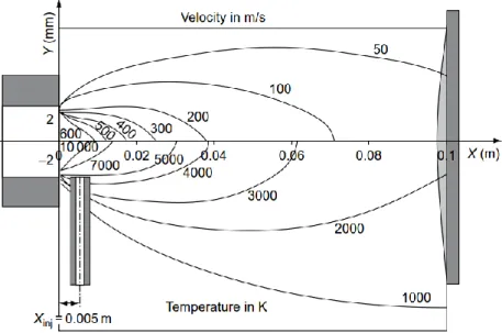
Figure 4: Calculated velocity and temperature distribution for the F4 plasma torch.
Typical torch powers range from 30 to 90 kW but high-powered torches can reach elec-trical power over 250 kW. Powder flow rate for typical torches is 3-6 kg/h with deposition efficiency around 50 %. Arc voltages range from 30-80 V with a current of 300-1000 A. The plasma jet can reach temperatures of 12000-15000 °C with velocities up to 500-2500 m/s at the nozzle exit. However, the velocity and temperature drop after the nozzle exit is significant as can be seen from Figure 4, this happens mainly due to turbulent mixing with the surrounding air. [2] Actual particle velocities and temperatures are noticeably lower.
Cooling water is required due to high thermal loads especially on the cathode but also on the anode. High flow rates and pressures are essential to prevent water vapour formation, which would result in a lowered heat transfer rate ultimately resulting in electrode over-heating and melting. The working gas is fed to the back of the spray torch where it passes through a gas distributor ring, which evens and redirects the flow. Often a gas vortex is formed inside the arc chamber. The rotating gas keeps the arc in motion to prevent the anode from eroding locally. As the gas is ionized, it expands and exits the spray torch. [1] An internal radial powder feed is shown in Figure 3 (p. 11) but external radial powder feed is also common. For radial feeding, one port is typically used but multiple port de-signs are available [4]. In advanced systems that utilize three electrodes instead of one, the powder feed can also be located axially between the electrodes. When injected directly along the centreline of the plasma, uniform heating can be achieved. Another advantage of the 3-electrode design is the reduced thermal load on the electrodes as the energy is divided which leads to a longer service life and makes higher power levels possible. [3] With internal powder feeding, both axial and radial, a great advantage is the longer parti-cle dwell time in the plasma jet. However, internal powder feeding requires a tighter size distribution for the feedstock powders. [1]
When using radial powder injection, care must be taken to optimize the powder feeding parameters as they affect the final powder velocity and degree of melting, which translate to the coatings characteristics. Powder size distribution, carrier gas velocity, powder feed port diameter and position determine the initial trajectory of the powder when it enters the plasma. When feeding the powder with enough velocity, larger particles have enough momentum to penetrate to the plasma centre while smaller particles remain in the cooler areas where they still heat up sufficiently. Too high or low carrier gas and powder flow rate and the powder feed will miss the centre of the plasma jet. A typically used powder size for plasma spraying is 10-45 µm. [1]
Powder feed should be aimed towards the centre of the plasma jet, when using external feeders they should be positioned precisely every time adjustments are made. A straight 90° angle to the plasma axis is commonly used but directing the port upstream of the plasma jet will result in longer dwell times, which may be beneficial for high melting
point materials, similarly directing the port downstream results in less heating. A small diameter powder feeding port creates higher velocities and therefore port erosion. Wear should be monitored, as even slight wear will result in decreased powder injection veloc-ities. [1]
The type of gas used in a plasma torch defines the plasma characteristic. Different plasma gases can be evaluated based on the achievable plasma jet temperature and the plasmas thermal conductivity. Helium reaches high temperatures and has good thermal conduc-tivity, but is often too expensive. Argon also produces a high temperature plasma but conducts heat poorly making it ineffective at heating powder particles. Hydrogen is an effective secondary gas as it increases the enthalpy and heat conductivity of the plasma also increasing the arc voltage. Nitrogen on the other hand is challenging to ignite and use. [3] In some applications, pure argon is used but combinations such as Ar+H2, Ar+He and Ar+N2 are used for their combination of high temperature and good heat conductivity. Nitrogen can be also utilized alone but it is also used together with hydrogen as a mixture. Ternary mixtures of Ar+He+H2 or Ar+He +N2 are also used. [4]
The torch nozzle and anode design is one of the determining factors of the plasma jets characteristics. Generally, smaller diameter nozzles increase the plasma temperature, though the increase is not as drastic as with changing the plasma gas composition. With small diameter nozzles velocity increase is however twofold: a smaller channel diameter on its own increases the flow but the raised plasma temperature increases it even further. Cylindrical nozzles are common in plasma spraying but diverging Laval-type nozzles have been found to create a more uniform velocity and temperature and reduce turbulence with the surrounding air. The cathode shape has an effect mainly on the velocity. A sharper cathode tip provides faster axial velocities but due to increased erosion rate the shape changes thus altering the velocity distribution. [2]
Arc current and plasma gas flow are the main parameters that are adjusted and tweaked to create the optimal plasma characteristics; their effect is illustrated in Figure 5. Increas-ing the arc current increases both the velocity and temperature of the plasma jet and par-ticles. Increased current however creates more heat thus decreasing electrode life. A higher plasma gas flow rate results in higher velocities but in return, the plasma and par-ticle temperature is decreased. To maximize coating quality further a plasma jet with cer-tain characteristics has to be matched with the correct spraying distance. If the distance is too short, the higher impact velocities lead to porosity whereas too long distances lead to particles re-solidifying mid-flight. [2]
Figure 5: The effect of current and plasma gas flow rate on YSZ particle temperature
and velocity in an Ar-He plasma. [2] (p. 423)
Plasma spraying with its wide range of jet temperatures is capable of depositing coatings of virtually any material as long as its melting point and evaporation or decomposition points are not too close. Operating atmosphere presents some limitations though as some metals, cermets and non-oxide ceramics sprayed with APS tend to oxidize or decompose during flight due to exposure to surrounding air. For oxide critical applications, vacuum (VPS) or controlled atmosphere plasma spraying (CAPS) is used. [2]
APS sprayed metals include various iron, nickel and cobalt based alloys as well as other superalloys and molybdenum. These are typically for low or high temperature corrosion applications but wear resistant coatings are also applied. Cermets can also be sprayed in regular atmosphere, however especially WC and WC-Co coatings are easily oxidized or decomposed resulting in lower hardnesses. Cr3C2-NiCr is more resistant to oxidizing and is easier to spray with APS. [2]
Non-oxide ceramics are easily oxidized or decomposed so they are usually deposited with VPS or CAPS. Oxide ceramics on the other hand are the most popular material deposited by APS. Most common are aluminium oxide, titanium oxide, chromium oxide and zirco-nium oxide and their various mixtures. Alumizirco-nium oxide and titazirco-nium oxide are mainly for wear and corrosion resistance as well as dielectric applications; these are often used as mixtures of varying compositions as they provide better properties than pure oxide coatings. The main applications of chromium oxide are also wear and corrosion re-sistance, it is also sometimes alloyed with aluminium oxide or titanium oxide. Zirconium oxide is primarily used in thermal barrier coatings due to its low thermal conductivity and high thermal shock resistance. [2]
The range of possible coating characteristics is wide, but for typical plasma sprayed coat-ings thicknesses are in the range of 300-1500 µm [3] with 2-8 % porosity and bond strengths over 40 MPa. With suspension plasma spraying for SOFC applications coatings as thin as 10 µm are however possible. [1] Usually low porosity levels are desirable but for thermal barrier coatings much higher porosity levels are advantageous and are achieved with the right parameters. Higher bond strengths are also achieved in some cases. [1]
High velocity oxy-fuel spraying
In high velocity oxy-fuel spraying (HVOF) a gas or liquid fuel is continuously injected with oxygen into a combustion chamber in the spray gun, the mixture is ignited to initiate the combustion process. The combustion generates high-pressure gases, which exit through a narrow barrel. Feedstock powder or liquid is injected into the stream heating and accelerating it tremendously. The jet exits the spray gun nozzle at supersonic speed. [1] A variation of the HVOF process is high velocity air fuel spraying (HVAF), where oxygen is replaced by compressed air resulting in a far more economical process. Com-pared to HVOF, HVAF produces higher velocities but colder flame temperatures. [2] HVOF guns come in a variety of designs, the differences are mainly related to fuel com-patibility, combustion chamber design and powder feed systems. Guns can be classified into four categories based on these factors; the variations are illustrated in Figure 6. In a gun with an axially aligned powder feed and combustion chamber (Fig. 6a) the powder injection port is located in the back of the combustion chamber and the combustion gases and powder feedstock exit through a water cooled nozzle. The next design (Fig. 6b) is similar to the one described earlier but the oxygen-fuel mixture in injected into a com-bustion chamber at a right-angle in relation to the axial powder feed direction. In another gun variation (Fig. 6c) the combustion is not confined into a nozzle and is similar to a flame spray torch. In systems utilizing liquid kerosene (Fig. 6d) the powder is often in-jected into the nozzle radially. [1]
Figure 6: Different commercially available HVOF torch models.
a) HV 2000 b) JetKote c) Diamond jet d) JP-5000 [1] (p. 40)
Table 1: Fuel properties. [3] (p. 94)
Fuels Max. flame T [°C] Mixing ratio at max. flame T [m3/m3] Calorific values (Hu) [MJ/m3] Acetylene 3160 1:1,5 56,5 Ethene 2924 1:2,4 93,2 Hydrogen 2856 1:0,42 87,9 Propylene 2896 1:3,7 56,5 Propane 2828 1:4,3 10,8
Natural gas (as methane) 2786 1:1,8 33,9
Kerosene ~2800 1:2,9 38 (MJ/l)
The following fuels are typically used in HVOF processes together with oxygen: acety-lene (C2H2), ethene (C2H4), hydrogen (H2), propyacety-lene (C3H6), propane (C3H8), natural gas (consisting mostly of methane) and liquid kerosene. The type of fuel used has little effect on the spraying velocities but their effect on flame temperature is much greater. Fuel properties, including maximum attainable temperatures and optimum mixing ratios and calorific values are compiled into Table 1. The fuel is selected according to the torch being used and the material being sprayed to optimize coating quality. [3] Power levels for guns using gaseous fuel is 100-120 kW with possible powder flow rates up to 7,2 kg/h, for liquid fuels power levels go up to 300 kW with a 12 kg/h powder flow rate. Deposition efficiencies are noticeably higher for HVOF compared to APS, 70 % for gaseous fuels and 60-80 % for liquid fuels. [2]
Compared to the plasma spraying process, HVOF spraying is relatively simple as far as different parameters go. Excluding acetylene, there is not much difference in the attaina-ble flame temperatures of the fuels. The temperature can also be regulated by varying the mixing ratio, increasing the oxygen flow decreases the temperature but increases the ve-locity through increase of total gas flow. On the other hand decreasing the oxygen amount decreases the temperature as well as the velocity. For air-cooled systems, increasing the flow of compressed air cools the flame without affecting its flow. [3]
Throughout the development of HVOF torches, maximum combustion pressure has been constantly increasing resulting in higher velocities. With 1st and 2nd generation torches operating at 3-5 bars, particle velocities have been over 400 m/s. For the 3rd generation torches with 6-10 bar operating pressures velocities up to 650 m/s are possible [3]. An-other method of increasing particle velocities is nozzle design; the capabilities of straight barrel nozzles are limited but the use of for example converging-diverging de Laval-noz-zles has been shown to increase particle velocities tremendously [2].
Various metals and alloys have been successfully sprayed with the HVOF process includ-ing: nickel and cobalt alloys, high alloyed steels as well as molybdenum, copper and al-uminium alloys. Coatings exhibit low levels of porosity and good bond strength (>50 MPa) resulting in high quality anti-corrosion coatings. [2] The most HVOF sprayed material group is cermet-composites, most notable being WC-Co and Cr3C2-NiCr which are used extensively for their wear and corrosion resistance. Compared to plasma spray-ing, HVOF sprayed WC-Co exhibits less carbide decomposition due to lower spraying temperatures. [2] A typical particle size for powder feedstock is 5-45 µm [4].
HVOF spraying of chromium oxide, aluminium oxide, titanium oxide and their mixtures has been successfully executed with positive outcomes but it is challenging and requires optimization of particle heating due to extremely high melting temperatures of the mate-rials. In one study titanium oxide was successfully sprayed and it was also found that having a narrow size distribution is crucial as large particles are easily left unmelted. [5] For example HVOF sprayed aluminium oxide, chromium oxide and their mixtures have been found to be harder, tougher and more wear resistant than their APS sprayed coun-terparts [6][7][8].
3. THERMAL SPRAYED OXIDE COATINGS
Thermal sprayed ceramic coatings are widely used in various industries especially for wear and corrosion protection, thermal and electrical insulation as well as other special-ized applications. Oxides are most prominent ceramic group in thermal spraying due to their cost-effectiveness, stability and good material properties. [9] Thermal spraying of non-oxide ceramics is often more challenging due to their susceptibility to decompose or evaporate during processing. Some carbides, borides and nitrides can be sprayed but even then, they typically require a controlled atmosphere. [2]
The majority of the powders used in thermal spraying of oxides are manufactured by fusing and crushing or spray drying, powders made with both methods are shown in Fig-ure 7. Fused and crushed powders start by fusing the raw material in a furnace above the materials melting temperature. The produced block of material is then broken up, crushed and milled to produce the powder. Fused and crushed powders are sharp and blocky with little internal porosity. The coarse shape makes for poor flowability, which can cause irregular powder feed during spraying; this can be addressed with a further spheroidiza-tion treatment in flame or in plasma but there is a risk of internal porosity formaspheroidiza-tion. Another problem with fused and crushed powders, at least in the case of chromium oxide is the formation of metallic chromium through a high temperature reducing reaction. This can be detrimental to the coatings qualities, especially if electrical insulation is required. [4]
Figure 7: Fused and crushed Cr2O3 powder (left),
spray dried Cr2O3+SiO2 powder (right). [4] (p. 11, 16)
Spray drying starts with a slurry, which contains precursors to form the solid powder, an organic binder to bind together the agglomerates after drying and additives to enhance slurry or binder properties. The slurry is fed into an atomizer where it is sprayed with high pressure to form fine droplets. Atomizing is followed by drying with heated gas, which
evaporates the moisture leaving behind solid powder agglomerates. The resulting parti-cles are globular with good flow properties but also porous and sometimes hollow which is caused by the rapid moisture evaporation rate. The morphology of the powder depends on the atomization and drying parameters as well as the slurry composition. Spray dried powders can be further densified by sintering, heating in an arc plasma or radio frequency plasma. This additional processing step creates much denser powders that heat and melt better during spraying. Due to this extra thermal processing step, phase changes are pos-sible and should be taken into account. [4]
Oxide materials require very high temperatures to properly melt and deposit via thermal spraying, therefore plasma spraying is frequently utilized to deposit them. Although the particles properly melt in the plasma jet, their velocities are low resulting in porosity and poor cohesion. Within the last 15 years, progress has been made in the field of HVOF spraying enabling the utilization of HVOF spraying for deposition of high-quality ce-ramic coatings. It is best to use internal powder feeding so that the powder is fed straight to the hottest section maximizing heating. When proper particle heating is achieved, HVOF spraying provides ceramic coatings with better structures than APS. [3]
In a study to chart the effect of different microstructural characteristics on the properties of ceramic coatings chromia, alumina and alumina-titania coatings were plasma sprayed with a few different parameters. When comparing the wear properties of the coatings and bulk ceramics it was found that the coatings had markedly higher wear rates than ceramics of the same hardness level suggesting that the unique microstructure of thermal sprayed coatings greatly affects the coatings wear properties. Namely, a good connection was found between hardness, porosity and wear volume. A definite link was also found for vertical crack density and wear particle size. [10] Even though bulk ceramics and thermal sprayed ceramic coatings are chemically similar in composition, the processing route af-fects their properties to a great degree, emphasizing the need for careful process control and improvement. Besides wear resistance, the unique microstructure affects their corro-sion properties as well. Ceramics are chemically quite inert materials but ceramic coatings are rarely dense with zero through porosity. This means that corrosive substances can often seep through the coating and corrode the underlying substrate. This can however be prevented with for example polymer impregnation of the coating. [4]
Alumina (Al2O3) is one of the most common and cost-effective oxides on the market as it is widely utilized in abrasives. Alumina coatings are good options for abrasion and corrosion in acidic environments but they are not suitable for alkaline environments. [3] Due to its dielectric properties, alumina is also used extensively as an insulating coating. The coatings are however relatively brittle which poses some limitations. During thermal spraying the α-alumina transforms to metastable alumina during rapid cooling. The γ-phase is stable up to 950 °C where it transforms back to the α-phase. The resulting phase
change is accompanied by a change in volume resulting in coating failure; therefore, the high temperature applications of pure alumina coatings are limited. [2]
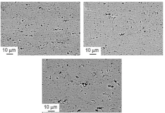
Figure 8: A) HVOF sprayed conventional Al2O3, B) HVOF sprayed nano-Al2O3,
C) APS sprayed conventional Al2O3. [11] (p. 4815)
Alumina is often used with titania additions of 3-40 % to enhance its properties, titania additions up to 13 % increase the coatings wear resistance by improving its toughness even though hardness is usually decreased [2]. Chromia additions on the other hand have been successfully used to create stable α-phase in the as-sprayed state [12], which results in overall better properties than pure alumina [13]. HVOF spraying of alumina has been shown to improve its properties resulting in less porosity (see Figure 8), better cohesion, higher toughness and hardness and of course better wear resistance then their APS sprayed counterparts. Nanostructured feedstock powder increased the properties further but only slightly. [6][7]
Titania (TiO2) and titania containing mixtures are amongst the easiest to spray as titania has the lowest melting point of the oxides at 1850 °C. [3] Titania is used in similar appli-cations as alumina but overall its properties are inferior.Titania is commonly mixed with other oxides, coatings containing titania result in lower hardness but higher toughness and less porosity [4]. As with alumina, HVOF spraying of conventional titania and nanostruc-tured titania powders also demonstrated significantly better abrasion resistance and coat-ing adhesion compared to APS sprayed titania. [14]
Zirconias (ZrO2) primary application lies in its thermal properties, for a ceramic material it has a very high thermal expansion coefficient, close to that of steel [3]. It also exhibits very high thermal shock resistance and a very low thermal conductivity, overall making
it an excellent choice as a thermal barrier coating. As other ceramics, pure zirconia also has other possible phases in high temperatures but zirconias phase structure can be stabi-lized with additions of yttria (Y2O3), ceria (CeO2) and magnesia (MgO), yttria stabistabi-lized zirconia (YSZ) being the most widely used. It is also being used in solid oxide fuel cells as an electrolyte where it is applied as a thin layer. There are also reports of zirconia being successfully sprayed by HVOF. [2]
Chromium oxide coatings
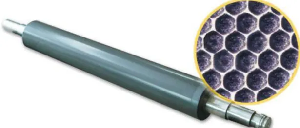
Thermal sprayed chromium oxide coatings can ideally reach hardnesses in the range of 1900-2000 HV; they have excellent wear resistance and a good surface finish. Compared to other thermal sprayed oxides, chromium oxide has relatively low levels of porosity and is insoluble in acids, alkali or alcohol. This makes chromium oxide an appealing coating for applications such as anilox rolls (Figure 9), pump seals and wear rings. Pure chromium oxide consists of stoichiometric α-Cr2O3 and is green in colour but during spraying the stoichiometric Cr2O3 may partially reduce to a non-stoichiometric composition that ap-pears darker in colour and has slightly inferior properties, partial reduction to metallic chromium is also possible, careful optimization of the spraying process is thus necessary. [2]
Figure 9: An anilox roll with a chromium oxide coating laser engraved with dimples
that transport ink. [15]
Chromium oxide is not always used as a pure coating as other ceramic additions enhance the coatings properties. While pure APS sprayed chromia yielded a porosity of 2,15 % and a hardness of 1140 HV, a mechanically mixed composite powder with 10 wt% alu-mina only had a porosity of 0,77 % and a hardness rating of 1437 HV. A mixture con-taining equal parts of chromia and alumina on the other hand yielded the highest fracture toughness. [13] Titania is also commonly used with chromia to increase its toughness; varying compositions from 4,25 wt% to 40 wt% are available on the market. Silica (SiO2)
is also used together with titania to enhance the toughness further. [16] Titania also helps reduce the oxygen loss during spraying [17].
Other more uncommon additives like MoO3 [18], CaF2, Ag2O and ZrO2 [19] have also been studied to some extent. MoO3 was found to reduce the porosity and increase the hardness of the coating as well as lower the coefficient of friction in normal and elevated temperatures. Cr2O3-Ag2O-CaF2 (CAF) and Cr2O3-ZrO2-CaF2 (CZF) coatings had a lower hardness than pure chromia coatings and higher coefficient of friction at room tem-perature. Since CaF2 is a high temperature solid lubricant, it lowered the composite coat-ings friction coefficient at higher temperatures. Of the two composite coatcoat-ings, CAF per-formed better as Ag2O improved the transfer films wettability whereas ZrO2 hindered its formation.
Apart from additives and spraying parameters, another method of improving the proper-ties of ceramic thermal sprayed coatings is the use of nanostructured powders. Plasma spraying of conventional fused and crushed chromia powders and a sol-gel produced nanostructured powders produced coatings with a remarkable difference in their wear re-sistance. In an oscillating wear test, the conventional coating had a wear rate 20-times higher than the nanostructured coating. [20] A similar study was also made with Cr2O3– 3%TiO2-powders, conventional and nanostructured. Nanostructured coatings had a higher hardness and resisted erosion and dry sliding better than the conventional coatings. [21]
Chromia is often selected for applications requiring good tribological properties, mainly wear resistance. Chromia is however not always an ideal solution for wear applications amongst thermal sprayed ceramic coatings. When tested in a dry sand-steel wheel test an alumina coating outperformed the chromia coating, both coatings were plasma sprayed and had a porosity of 6 %. Within the scope of the same study, same samples were also tested in a pin-on-disk tribometer, this time chromia experienced less wear than the alu-mina coating. The measured friction coefficients and pin material losses were also lower with the chromia coating than with any other tested coatings. Success of chromia was attributed to the formation of a compact tribofilm through plastic deformation. [22] The tribofilms formed by plasma sprayed chromia coatings in dry sliding have been stud-ied in another study in more detail. Cr2O3-3%TiO2-5%SiO2 coatings were tested in a re-ciprocating dry-sliding test at room temperature and at 450 °C. The total wear was higher in the 450 °C test; however, the coefficient of friction was lower. This was explained by the fact that due to the higher wear amount in the beginning of the 450 °C test, a more pronounced tribofilm with a higher hardness was formed. Through an XPS analysis it was discovered that the wear films differed also in chemical composition from the as-ground surfaces, films formed in the test at room temperature showed signs of CrO3, while the test at 450 °C produced films with CrO2. [23]
To investigate the abrasive wear behaviour of alumina and chromia coatings, a single point scratch test was utilized. With low contact pressures, the chromia coating had a high wear resistance, the primary material removal mechanism being microfracture originating from existing cracks and pores. However, when a critical contact pressure limit was ex-ceeded, lateral cracks beneath the contact area formed causing macro-fracturing. [24] The macro-fracturing is most probably associated with weak cohesion between coating layers, often visible in plasma sprayed chromia fracture cross-sections as can be seen in Figure 10 [6].
Figure 10: APS sprayed chromia coatings fracture surfaces. [6] (p. 48)
Figure 11: Wear tracks on alumina (A) and chromia (B) coatings. [7] (p. 69)
Wear tests conducted on HVOF sprayed chromia and alumina coatings demonstrated a significant improvement in wear properties over APS coatings. In dry sliding tests chro-mia coatings fared better due to the formation of a more uniform, durable tribofilm (see Figure 11). When the contact pressure was increased the influence of the higher toughness exhibited by the HVOF coatings became evident. Chromia coatings also worked better than alumina coatings against abrasive wear in the dry sand-rubber wheel test, the HVOF
sprayed chromia having the lowest mass loss. [7] HVOF and APS sprayed ceramic coat-ings were also studied in [25] and similar improvement in microstructure and properties were noted in HVOF coatings. HVOF and plasma sprayed chromia coatings were also tested in a cavitation erosion series with other sprayed coatings. Amongst all the tested specimens, including the cavitation resistant bulk stainless steels as reference samples, HVOF sprayed chromia had a mass loss in the same range as the bulk reference samples [26].
As a material on its own, chromia is resistant to acidic and alkaline solutions [2]. Various ceramic APS and HVOF coatings were tested in NaOH and H2SO4 solutions and chromia experienced very little mass loss being second only to the titania coating. In comparison the mass loss of the alumina coatings were several orders of magnitude higher. [27] Ther-mal sprayed ceramic coatings are not often used for corrosion protection as producing a ceramic coating absolutely free of cracks and through porosity is challenging. The use of a bond layer to increase the corrosion resistance of the coating system has been investi-gated, but the results with different bond coatings were similar: the bond coat corroded underneath the chromia layer resulting in failure at the interface. The bond coats that were chemically more corrosion resistant therefore naturally fared better. [28]
One possibility for improving the corrosion protection capabilities of chromia and other coatings is sealing the open porosity with organic or inorganic sealants. Organic sealants consist of resins, waxes and other polymeric materials. Inorganic sealants include sol-gel, aluminium phosphate and even molten metals. [4] Application of aluminium phosphate sealing has for example been studied with chromia coatings. The results indicated an im-provement in corrosion resistance as well as in erosion and abrasive wear resistance. [29] A post-spraying treatment however requires an additional processing step increasing the cost of the components.
4. SPRAYABILITY OF CHROMIUM OXIDE
Thermal spraying of chromia and ceramics in general is not simple due to their high melt-ing point, the use of plasma torches is a good start but havmelt-ing the correct operatmelt-ing pa-rameters is even more vital and their optimization has been thoroughly researched. HVOF spraying is another alternative for processing chromium oxide; the reachable tempera-tures are not as extreme as with plasma spraying but the improved particle velocity makes processing of ceramics viable. HVOF spraying of ceramics has been experimented with for at least 20 years [26][36] but it still remains relatively challenging due to the higher melting points of ceramic materials.
Plasma spraying of chromium oxide
Spraying parameters found in literature for plasma spraying of chromia differ somewhat. Primary plasma gas is often argon, while hydrogen acts as the secondary gas, in some cases helium is used in place of hydrogen. Arc current ranges from 500 A to 750 A with a voltage of 45-75 V, this results in 34-45 kW power. The powders used are either sintered and crushed or agglomerated and sintered typical particle size being 10-45 µm, powder flow rates range from 15 g/min to 25 g/min. Spraying distance is usually kept near 100 mm. [18]- [22]
In earlier experimental studies regarding plasma spraying of chromium oxide, the effect of different parameters was investigated. High current intensity, 500 A being the highest tested value in this study, was deemed important for good adhesion and low porosity. [30] The effect of substrate preheating also appeared important as peak adhesiveness was achieved with preheating to 400 °C. [30] In a similar study, the parameters affecting ad-hesion were studied in further detail. The results supported the earlier study about the importance of high current intensity and clarified the influence of surface preheating. Ev-idently, the time between substrate grit blasting and spraying is a key factor. [31]
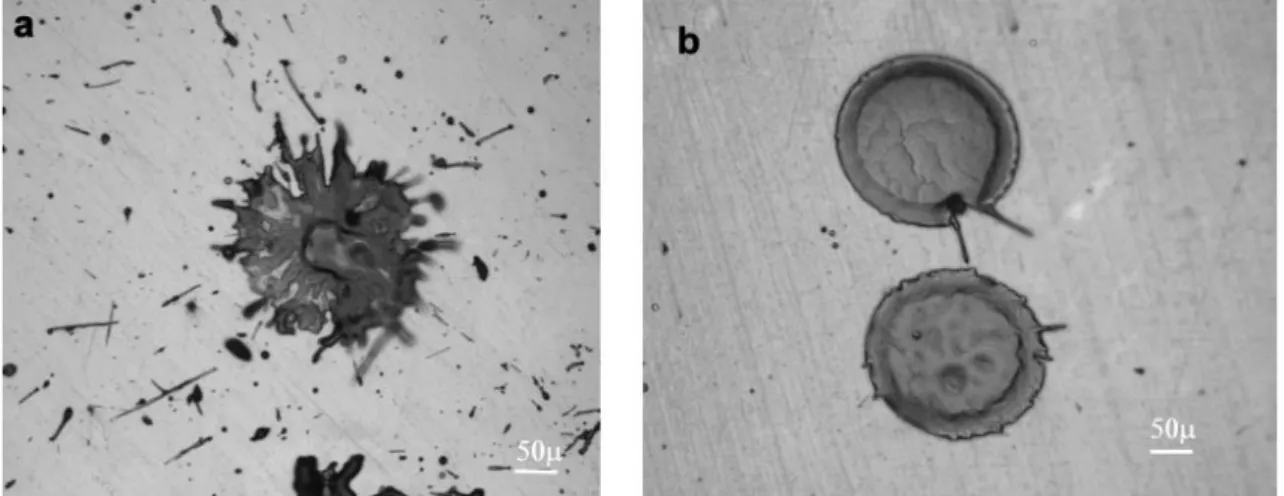
It was speculated that a longer time between grit blasting and spraying would allow the formation of a thicker absorption layer consisting of air, moisture and other impurities. If there had been a long time (2 h) between grit blasting and spraying, preheating increased the coating adhesion noticeably, most probably due to evaporation of impurities. If spray-ing was done immediately after grit blastspray-ing the need for preheatspray-ing was not as signifi-cant. [31] Studies regarding single-splat behaviour of chromium oxide were not available but studies on zirconia indicate that the purity of the surface is vital for clean splat for-mation rather than the high substrate temperature, see Figure 12 for details. [32] As far as
other pre-spray treatment goes, correctly executed grit blasting is also necessary, as in-creasing the surface roughness from 2,5 µm to 4-5 µm improves coating adhesion. [31]
Figure 12: Morphology of zirconia splats on polished substrates sprayed in
a low-pressure chamber. a) Sprayed on a substrate at room temperature.
b) Substrate was first heated to remove condensation, then cooled to room temperature, then sprayed. [32] (p. 149)
It was also found that the effect of the cooling jets and their positioning was the most critical parameter for chromium oxide coating quality; this was attributed to their cooling and cleaning properties as they were claimed to blow away unmelted particles from the surface. The setup consisted of two compressed air jets parallel on both sides of the plasma jet; the optimal lateral distance in this case was 30 mm. Even though the cooling jets were said to cause turbulences in the plasma jet, their use was still deemed beneficial. [31]
Other plasma spraying techniques besides APS have potential to produce superior coat-ings. Chromia coatings were made with a high-power 250 kW plasma spray system with different parameters and the higher velocities created the best coatings. [33] The high-power plasma spray system is capable of particle velocities twice the velocities of con-ventional APS, the faster particle impact velocities result in coatings with a higher hard-ness and lower porosity [34]. The high-power plasma spray system is also capable of 2-3 times higher spray rates which creates significant cost savings in industrial use [35].
HVOF spraying of chromium oxide
The higher velocities related to HVOF spraying have typically produced coatings of much higher quality than typical APS, this fact is already well known in the case of cermet coatings. For spraying of chromia the temperature (and velocity) should be maximized to ensure proper degree of melting, combustion gases used in literature include hydrogen,
propylene [6][25], ethylene [8] as well as acetylene [36]. Hydrogen provides a wide pro-cess window with high temperatures, while propylene is able to reach higher velocities. Even though acetylene has the highest flame temperatures, which is why some of the earlier HVOF chromia spraying trials were done with it, its flow rate is limited due to pressure limitations in actual use [36].
The used powder size is kept smaller than in APS due to the limited heating capability of the HVOF system, the usual powder size for ceramics in HVOF spraying is 5-15 µm. A tight size distribution makes processing easier and provides a wider process window [5]. Spraying distance is generally longer than with APS, 100-150 mm being common. Pow-der feed rates are similar to the values used with APS. [6][8][36] In earlier trials the shorter spraying distance has created coatings with better wear resistance, this might have been related to particle cooling and solidification during the longer flight [36].
Figure 13: SEM (BSE) micrographs of APS (left) and HVOF (right) sprayed 100 %
Cr2O3 coatings, both sprayed at TUT.
HVOF spraying of chromia has been shown to produce coating microstructures with lower porosity, less cracks and well-adhered splats compared to the APS sprayed samples, the existing pores are smaller and more evenly distributed. [25] These attributes of HVOF sprayed chromia are shown in Figure 13. Equiaxed and smaller columnar grains have also been examined in HVOF sprayed chromia; additionally, the same samples exhibited higher indentation fracture toughness and bending fracture behaviour similar to that of bulk materials. Vickers hardness and indentation fracture toughness was also improved in the HVOF samples compared to APS counterparts. [6]
The performance of HVOF systems for spraying chromia originate from the significantly higher velocities and cooler flame temperatures compared to APS. The degree of particle flattening is higher in HVOF sprayed samples, which makes for higher cohesion between splats. It is also postulated that due to nearly instantaneous flattening and high kinetic energy, solidification cannot start before flattening is complete, which results in higher
supercooling and the aforementioned equiaxed grains. [6] Due to the cooler flame, HVOF spraying reduces lesser amounts of chromia to metallic chromium. However, even though HVOF coatings had better properties, the deposition efficiency of the process was lower than with APS, this might however just be a matter of further process optimization. [8]
Vaporization of chromium oxide
There is little data related to the deposition efficiency (DE) of thermal spraying of chro-mia, which is possibly related to DE being challenging to measure reliably and therefore information is rarely published. Consensus within the research group suggests that chro-mias DE is low and what could be gathered from literature does support the claim. Dep-osition efficiency is inherently related to the spraying parameters and therefore will fluc-tuate greatly from process to process. In one particular study where the DE of plasma sprayed chromia was investigated in great detail the achieved DE values ranged from 26,6 % to 58,5 % depending on the torch parameters. [37] For HVOF using propane as fuel gas a 32 % DE has been reported. [38]
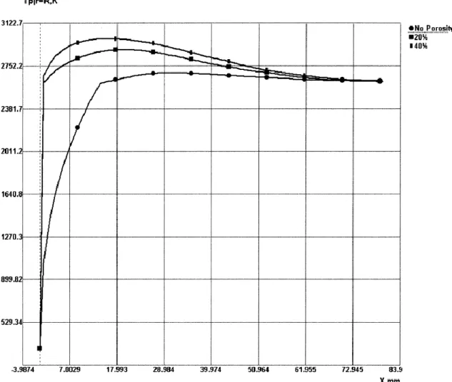
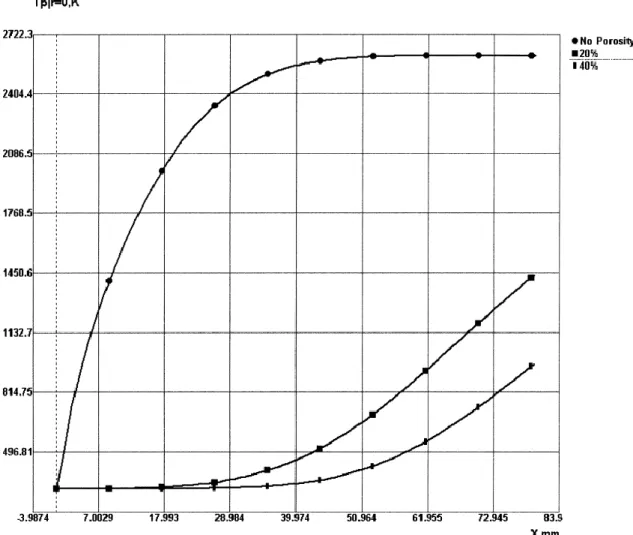
The low deposition efficiency is partially caused by unmelted particles when using low flame temperatures especially with HVOF systems, insufficient heating during flight of-ten also leads to poor coating quality. Chromia has a relatively high melting point Tm = 2334 °C (2607 K [39]) and a low thermal conductivity, which is decreased further by the porosity of individual particles. As the particle dwell times in thermal spraying are quite low, it is necessary to use high flame temperatures to properly melt the particles. However, this leads to another challenge: the vaporization of the feedstock powder and the resulting drop in DE in high temperature flames. [40] According to computer simula-tions, the temperature on the surface of 35 µm chromia particles can well exceed the melting temperature while the core remains solid. As can be seen in Figures 14 and 15, porosity plays a significant role in how particles behave during spraying. [39]
Figure 14: Surface temperatures of sprayed Cr2O3 particles with varying porosities in a plasma flame. (X = distance from injection port) [39] (p. 373)
Figure 15: Core temperature of sprayed Cr2O3 particles with varying porosities in a plasma flame. (X = distance from injection port) [39] (p. 374)
Research on the vaporization of chromia in thermal spraying processes and its effect on deposition efficiency and coating microstructure is scarce and the problem is rarely ad-dressed in literature. The actual amount of material vaporized from a stream of chromia particles is difficult to estimate and will always depend on the particle size distribution, internal porosity and flame parameters. The amount of vaporization in plasma spraying processes in general however, seems quite significant. Calculations have indicated that for iron particles (14-55 µm) the total amount of vaporized mass in plasma spraying can be up to 25 % with a high hydrogen content and high arc current. Lower plasma temper-atures naturally reduce the amount of vaporization. It was also documented that as the formed iron vapour cools it condenses into submicronic particles [40].
The vaporization and the consequent condensation of vapours has also been demonstrated for ceramics in the case of yttria-stabilized zirconia (YSZ). The results were similar to those conducted with iron particles, the YSZ powder vaporizes and condenses to submi-cronic particles (dust). The concentration of particles was measured and it was found to
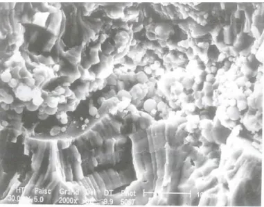
increase with increasing axial distance from the spray torch, meaning the dust concentra-tion was higher closer to the substrate. [41] This dust can accumulate on the substrate itself along with unmelted particles and get trapped between incoming molten droplets, such a phenomena has been demonstrated with alumina elsewhere, see Figure 16 [42]. Similar behaviour has also been speculated for chromia [31]. The inclusion of fine dust between each pass creates a poorly adhered layer between each pass, which leads to poor overall coating cohesion and a layered porosity in thermal sprayed chromia coatings. These microstructural factors further deteriorate the coatings wear resistance amongst other properties.
Figure 16: Interface of alumina beads with small spherical particles trapped between
columnar grains. [42] (p. 620)
We have concluded that vaporization affects multiple materials in plasma spraying due to the extreme temperatures in the process but what makes vaporization even more sig-nificant for chromia is the chemical reactivity in high temperatures and the formation of hexavalent chromium compounds. While chromia melts at 2334 °C and starts vaporizing above that, toxic hexavalent chromia compounds start forming below 1000 °C and will vaporize at much lower temperatures, which adds to the total amount of material loss. What actually happens to chromia in a thermal spraying environment has not been inves-tigated but studies related to the behaviour of chromium oxide in solid-oxide fuel cells and in waste incinerators will give some ideas as to the possibilities even though the tem-peratures and atmospheres are not exactly the same. When sintered Cr2O3 was held in a furnace in temperatures of 1000-1200 °C and subjected to pure oxygen or argon with or without moisture, several phenomena were documented. In an oxygen atmosphere, the sample showed signs of weight loss, which nearly doubled in wet oxygen. In argon, wet or dry, however, weight loss was zero. [43]
This indicated that a chemical reaction is behind the evaporation of Cr2O3. Thermody-namically the most feasible compound was speculated to be hexavalent chromium oxide CrO3 according to reaction 1.
Cr2O3(s) + 3/2O2(g) = 2CrO3(g) (1)
CrO3 is a metastable oxide but with high oxygen pressure its formation is likely. Its ex-istence was not verified in the furnace trials as it typically decomposes back to Cr2O3. When a Cr2O3 sample was heated with an oxy-gas torch, CrO3 was detected in the smoke that condensed on a cold surface. The CrO3 was retained possibly due to the rapid quench. [43]
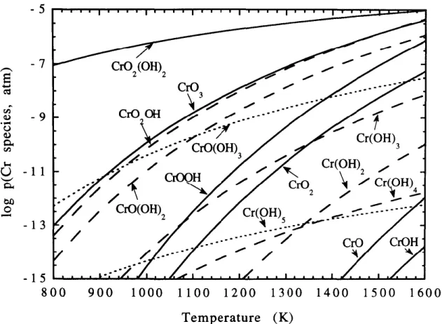
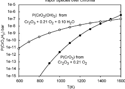
Figure 17: Logarithmic plot of chromium species partial pressures as a function of
tem-perature at p(H2O) = 0,10 atm and p(O2) = 0,10 atm. [44]
Another possibility for the dominant chromium species that forms is hexavalent chro-mium oxyhydroxide CrO2(OH)2, which forms according to reaction 2 and is also at-tributed as the reason for increased weight loss in wet oxygen environments.
Cr2O3(s) + 2H2O(g) + 3/2O2(g) = 2CrO2(OH)2(g) (2) Calculations indicated that when p(H2O) = 0,10 atm and p(O2) = 0,10 atm chromium oxyhydroxide CrO2(OH)2 would be the dominant vapour species. CrO3 is the second most
dominant in this system as illustrated in Figure 17.[44] With increasing temperature the relative amount of CrO3 increases and considering the higher range of temperatures in the plasma spraying process CrO3 may be the dominant species in that process. The formation of CrO2(OH)2 also necessitates the presences of moisture. In other computations done in a similar system where water vapour was not taken into consideration CrO3 emerged as the dominant vapour species [45][46].
Actual experiments agree to some degree with the aforementioned calculation results. Experiments were done in a constant temperature of 950 °C by variating the partial pres-sure of water p(H2O) from 0,0007 to 0,3. At p(H2O) lower than 0,005 bar, vaporization of Cr2O3 was independent of water partial pressure. With p(H2O) higher than 0,005 bar, vaporization rate increased with increasing water partial pressure. With low p(H2O), CrO3 was found as the dominating vapour species and it was claimed to be independent of p(H2O). Meanwhile CrO2(OH)2 was more prominent at higher p(H2O) and its partial pres-sure was strongly related to p(H2O). Additionally experiments done at constant p(H2O) = 0.02 bar the evaporation rate of Cr2O3 increased with increasing temperature. [47] The effect of temperature on the formation of CrO3 in dry air and CrO2(OH)2 in wet air is illustrated in Figure 18.
Figure 18: Calculated vapour pressures of volatile chromia species in dry and wet air.
[48]
In other experimental studies, lower temperature ranges in wet oxygen were covered through a transpiration technique. At 600 °C and below, mainly brown liquid chromic acid (CrO2(OH)2) was found. At 700-900 °C in addition to the brown deposit, green Cr2O3
was also discovered. Hexavalent chromium being an unstable compound it was noted that it tends to decompose above 400 °C, indicating that at higher temperatures the hexavalent vapours decompose and deposit as Cr2O3. Additional experiments to determine the effect of CrO3 on the total vaporization were also conducted at 900 °C in dry oxygen, it was concluded that its contribution was not more than 1 % in that temperature, once again emphasizing the dominance of CrO2(OH)2 at lower temperatures. [49]
What can be gathered from this array of experimental and theoretical studies is that, to minimize the vaporization of chromia, moisture has to be reduced in the spraying atmos-phere as moisture promotes the formation of the more volatile oxyhydroxide. Another factor to monitor is the spraying temperature; high flame temperatures naturally increase the overall evaporation rate. In this respect, HVOF appears as a promising technique, but on the other hand, it is possible that the higher amount of oxygen in the HVOF flame will promote the oxidation of Cr2O3 regardless of the lower operating temperatures. In a plasma flame the oxygen available for the reaction is mainly entertained by the surround-ing mixsurround-ing air currents.
In actual plasma spraying operations the amount of hexavalent chromium in process fumes has been measured in a few cases. Plasma spraying of pure metallic chromium powder yielded a 26-30 % fraction of hexavalent chromium out of total chromium in the collected fumes [51][52]. In a separate analysis for plasma spraying of 100 % Cr2O3 the amount of hexavalent chromium formed was 8,9 grams per kilogram of sprayed material [53]. The amount of process fumes and the amount of hexavalent chromium formed would naturally vary and would be affected by starting powder and most importantly the process parameters.
Health effects of hexavalent chromium
As stated, the fact is that hexavalent chromium vapours are present in thermal spraying processes involving chromium and chromium oxide, which creates problems for work safety, ventilation and waste handling. Even though part of the fumes condense back to the much more harmless Cr2O3 some are still retained due to rapid quenching [43] or via the formation of stable compounds with alkali metal impurities present in the spraying powder [50].
It has been proposed that the use of extremely pure chromia with alumina additions can reduce the vaporization and formation of hexavalent chromium compounds. Even if the amount of hexavalent chromium was reduced through process optimization, its complete elimination is highly unlikely. Therefore, the health risks associated with hexavalent chromium should be recognized by personnel working with these materials and respective measures should be taken to reduce exposure as well as limit environmental emissions.
People working with chromium containing compounds and materials may be exposed to hexavalent chromium through inhalation, skin contact or ingestion [85]. For thermal spraying operations, inhalation of fumes and dust is possibly the most prevalent. Ingestion may occur if food, cosmetics or tobacco are handled in the same space and are contami-nated as a result. The same dust may also land on the skin and get absorbed through it. [86] Overall, hexavalent chromium is not very easily absorbed through the lungs or the digestive system; it is however absorbed more readily than the trivalent form making it more hazardous. Hexavalent chromium is often reduced to its trivalent form by gastric liquids reducing exposure through ingestion. Absorption through skin contact is highly dependent on the compound and its form as well as the condition of the skin. [85] Acute effects of hexavalent chromium exposure include skin ulcers and allergic reactions. Ingestion of large amounts may lead to stomach ulcers, gastrointestinal bleeding, vomit-ing, kidney and liver damage and in extreme cases death. In most cases, chronic exposure is more common in the workplace; effects of chronic toxicity include ulceration, skin irritation and hypersensitization to other metals resulting from dermal exposure. Inhala-tion may result in nasal bleeding, loss of smell and taste as well as asthma. Hexavalent chromium is also classified as a carcinogen as an increase in lung cancer has been ob-served in people working in industrial facilities utilizing chromium compounds. [85][87] There are different levels of exposure permitted by various health and safety organiza-tions. In 2006, the Occupational Safety and Health Administration (OSHA) in the United States passed new regulations regarding hexavalent chromium exposure lowering the pre-vious limits by a factor of 10. The permissible exposure limit (PEL) was set as 5 µg/m3 as a weighted time average during an 8-hour shift. If the amount of chromium in air exceeds this limit, access to the area must be limited, air monitoring must be conducted every three months and respirators and special clothing is required for people working in said area. [88]
In addition to the PEL, OSHA also maintains a separate action level which is 2,5 µg/m3. When the chromium content is between 2,5-5 µg/m3 air monitoring must be implemented every six months and workers must be medically tested. [88] In 2013 the National Insti-tute for Occupational Safety and Health (NIOSH) published its own recommended expo-sure limit (REL) of 0,2 µg/m3 for hexavalent chromium [86]. Although the REL is only a recommendation, it indicates a clear trend towards lowering the limit gradually to re-duce exposure. The regulations in Finland controlled by the Ministry of Social Affairs and Health are similar to the ones implemented by OSHA as the concentration known to be hazardous is the aforementioned 5 µg/m3 weighted time average during an 8-hour shift [89]. Other related restrictions include the RoHS-directive (Restriction of Hazardous Sub-stances) where the amount of hexavalent chromium in homogenous materials is restricted to 0,1 wt% [90].
5. AUXILIARY SYSTEMS FOR COOLING AND
CLEANING
As a process technology, thermal spraying is still evolving, new and existing materials are being sprayed with new generation torches with optimized parameters providing coat-ings with longer lifetime and enhanced properties. Simply modifying the spraying condi-tions to reach higher or lower temperatures and higher velocities however is limited in terms of coating evolution. At times the des