Copyright © 2018 EMITTER International Journal of Engineering Technology - Published by EEPIS
168
Stator Flux Estimator Using Feed-Forward Neural Network
for Evaluating Hysteresis Loss Curve in Three Phase
Induction Motor
Bayu Praharsena1, Era Purwanto2, Arman Jaya3, M. Rizani Rusli4,
Handri Toar5, Ridwan6
1,2,3,4Politeknik Elektronika Negeri Surabaya, Surabaya, Indonesia 5,6Politeknik Negeri Batam, Batam, Indonesia.
1[email protected], 1[email protected],
2[email protected], 3[email protected], 4[email protected], 5[email protected], 6[email protected]
Abstract
The operation of induction motors with high performance contributes significantly to the global energy savings but hysteresis loss is one of the factors causing decreased performance. Stator flux density (B) and magnetic field intensity (H) must be plotted to know hysteresis loss quantity. Unfortunately, since the rotor rotates in time series, the stator flux density is unmeasurable quantities. It is hard to directly detect this properties because of limited airgap space and costly installation of additional instrument The purpose of this paper is to evaluate the hysteresis loss quantity in induction motor using a novel method of multilayer perceptron Feed Forward Neural Network (FFNN) as stator flux estimator and magnetizing current model as magnetic field intensity properties. This method is effective because it’s non-destructive method, without an additional instrument, low cost, and suitable for real-time motor drive systems. The FFNN estimator response is satisfied because it is accurate to estimate stator flux density for evaluating hysteresis loss quantity including its magnitude and phase angle. By using the proposed model, the stator flux density and magnetizing current can be plotted to be hysteresis loss curve. The performance of flux response, speed response, torque response and error deviation of stator flux estimator has been presented, investigated, compared and verified in Simulink Matlab.
Keywords: Feed-Forward Neural Network, hysteresis loss curve, induction motor, Matlab Simulink, stator flux estimator.
1. INTRODUCTION
EMITTER International Journal of Engineering Technology, ISSN: 2443-1168 rugged, low cost, low maintenance, robust to severe operating conditions, robustness and good efficiency [3] [4] [5] [6] [7], able to endure high temperatures, and robust to mechanical shock, vibration [8] and suitable to be used as a prime mover in the industrial sector.
The induction motor has several losses, including iron loss which consists of hysteresis loss and eddy current loss. The hysteresis loss and eddy current loss are proportional to the square of the stator flux density. But, the eddy current loss is proportioan to 2
e
and the coeffisient loss is inversely
proportional to the stator flux curve. Thus, the hysteresis loss becomes dominant when the motor operates in the low-frequency [9], [10]. In industrial sector, induction motor widely operate on low frequency for conveyor, crane etc. The hysteresis loss mechanism can be described as hysteresis loss curve which calculates the curve area between stator flux density (B) and magnetic field intensity (H) [9]. In fact, the B and H were not parallel under two directional excitations. It will be hard to determine the quantity of hysteresis loss with the conventional measuring methods.
Based on all cited, there are two different methods to get magnetic flux value. The first method is related to direct measurement by using flux sensor or another instrument. The second method uses intellegence algorithm to estimate the behaviour of hysteresis loss. Since the rotor rotates in time series, the stator flux density is unmeasurable quantities. It is hard to directly detect this properties because of the space limitation. Hence, the second method is more powerful, effective, non-destructive method, without additional instrument, low cost, and suitable for real time motor drive systems. It can be done by estimating the stator flux density using artificial intelligence and calculating the vector magnetic properties on the induction motor. By using the multilayer perceptron feed forward neural network algorithm, it becomes good solution for estimating this quantities which is related to several important aspects of induction machine behaviour. It consists enough elements (called neurons) which can be modeled to the dynamic systems with arbitrary accuracy which are particularly well suited for addressing non-linear dynamic problems like nonsensored B on rotating machine. On other side, the H has been presented in the space vector which is proportional to the magnetizing current model. This paper describe the evaluation method for hysteresis loss of induction motor using feedforward NN as B estimator and magnetizing current model as H properties. This method is non-destructive method, and without additional instrument, so this method are low cost, effective and suitable for real time motor drive systems.
2. RELATED WORKS
EMITTER International Journal of Engineering Technology, ISSN: 2443-1168
high cost to use that sensor. Moreover, flux sensors are sensitive to temperature and noise. Mikaela Ranta et al [13] discusses nonlinear inductance function and nonlinear iron-loss resistance function. This method was tested with FEM on a 45Kw induction motor. Herzog and Buechelr [14] discuss modeling complex inductance for plotted iron loss of permanent magnet induction motor. Enokizono & Oka evaluate hysteresis loss and eddy current loss on stator core induction motor using excitation inner core method [15]. The scientific literature [16] [17] offers more accurate space vector dynamic models to consider B and H on rotating machine. Based on [18] [19] [20], hysteresis loss is defined as vector magnetic properties. This research discusses about dynamic E&S model and FEM to generate the hysteresis loss equation of induction motor. Based on [21], calculation proccess of flux uses ANFIS flux estimation.
3. ORIGINALITY
This paper describes an evaluation method for hysteresis loss quantity in induction motor using a novel method of multilayer perceptron feed forward neural network as stator flux estimator and magnetizing current model as magnetic field intensity properties. By using the proposed method, the stator flux density and magnetizing current can be plotted to hysteresis loss curve.
4. SYSTEM DESIGN
This section defines a full detail of particular method over evaluating hysteresis loss. This design isstarting from the magnetic field intensity which is modeled on magnetizing current properties. The second sub-section discusses about stator flux density to make clear about stator flux estimator and stator flux observer. The first and second sub-section become important piece for generating hysteresis loss curve. After defining all induction parameters, the third sub-section discusses about speed and torque control based on stator flux observer.
4.1 MAGNETIC FIELD INTENSITY OF INDUCTION MOTOR
In the conventional method, the H was calculated by B which is divided by permeability factor. Unfortunately, permeability factor is affected from motor’s materials. On other hand, it is hard to measure directly in real-time condition because of temperature sensitivity and limit space on motor’s construction. As technology develops, the hysteresis properties are analyzed by vector magnetic characteristic [16] [17], by using vector hysteresis analyzer (V-H analyzer) to generate the vector magnetic characteristic. The conventional property represents the relation of magnitude between B and H
EMITTER International Journal of Engineering Technology, ISSN: 2443-1168 current respect to phase current. This value expresses two component, that real and imaginary value. The correlation between stator flux density and magnetizing current exist is not only magnitude but also vector direction [16],[17],[18]. Using simulation result, it can be represented as space vector expressed on two orthogonal axes by the complex form related with stator magnetizing current and stator flux density including phase magnitude and angel vector direction.
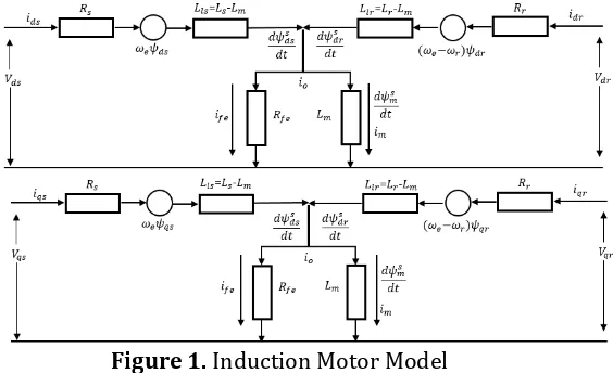
To generate the vector magnetic model, The induction motor with squirrel cage rotor is transformed using Clark-park transformation to be two phase representation in d-q coordinated. This model considers with the vector control algorithm that provides a high quality of drive performance to control separately the torque and stator flux based on hysteresis loss properties. The main concern of this paper is about stator flux density and magnetizing current model. So induction motor model which depends on this component can be described in the model as follows:
Figure 1. Induction Motor Model
Where the superscript s denotes the stationary frame. With respect to model dependence, the space vector stator voltage model can be considered as a function of the sensitive observer to stator resistance Rs, electrical speed
s
and stator inductance Ls. Refered to H, the complex vector model including iron loss resistance is used for correction factors to accurate acccount of saturation effect in induction mechanism.
s s
Since the magnetizing current in the air gap between stator and rotor time-derivative dim
dt is also small, and saturation current magnetization
EMITTER International Journal of Engineering Technology, ISSN: 2443-1168 current, iron loss resistance should be add to the magnetizing current model. Considered to steady state operation, the vector trajectory between mthe agnetizing current in d-aqis and q-axis becomes perpendicular. The resultan vector can be represened as fthe ollowing equation.
inductance which equals to Lm due to the magnetizing flux crossing the air gap of the induction motor, the mutual inductance is designed with a small value, with magnetizing current as a reference. So the iron loss resistance becomes very influential on muntual flux. In steady state operation, the mutual inductance will be constant (angular frequency effect). So the mutual induction and iron loss resistance are referred as the magnetizing coefficient
m
which is assumed that motor is operation in constant themperature, and winding. It is affected by the second derivate of the magnetizing coefficient. Second, the saturation effect limits the magnetizing current and it makes a saturation effect.
EMITTER International Journal of Engineering Technology, ISSN: 2443-1168
4.2 STATOR FLUX ESTIMATOR USING FEED-FORWARD NEURAL NETWORK
Usually, a motor drive works with a rated stator flux, but at low loads, it produces high iron losses that decrease motor efficiency. It is well known that varying the stator flux below the rate value can improve motor efficiency. Estimation of the stator flux at the present time is required. the stator flux estimation is based on the stator voltage equation:
0
Considered the case where s is not a linear function of stator current [22], the voltage model in (8) can be multiple with stator current function in time series. So this equation becomes power distribution function in which the power in the stator winding is assumed as W. The (8) can be rewritten as:
0 and (10) can be rewritten as:
EMITTER International Journal of Engineering Technology, ISSN: 2443-1168
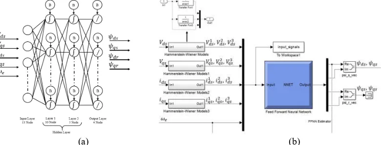
the hidden layers (3 layers) and to the output layer. This system consists of multiple layer of computational units. The units of these networks apply a sigmoid function as an activation function. FFNN algorithm and its function are provided by Neural Network Toolbox package in Matlab. First, initially the untrained network, weight and bias selection in a random manner the output signal ds, qs, dr, qr will totally mismatch the desired output pattern for reference input signal V Vds, qs, , ,i ids qs e. The actual output
pattern then is compared to the desired output pattern by adjusting the weights until the pattern signal maching occurs and the error relatively is small. Based on neuron model and network architectures for multiple layer networks, we use tansig activation function in hidden layer to determine the weight matrices and purelin activation function in output layer as shown in Figure 2.
(a) (b)
Figure 2. (a) Neural network structure, (b) Neural network and Hammerstein-Wiener Models
Where V Vds, qs, , ,i ids qs e are the input vector and ds, qs, dr, qrare the output vector. So the correlation between input function and output layer can be shown as.
ds, qs, dr, qr
f V Vds, qs, , ,i ids qs e
( 13 ) A three-layer structure of the neural network is selected, that implies a number of neurons, bias, activation function, training algorithm and its shown on Figure 2. Neural network structure implemented is given as follows:Configuration: Three Layers Number of Neurons: 10-5-4
Activation function: Tansig, Purelin
Training algorithm: Bayesian regularization Performance: Mean Squared Error (MSE)
EMITTER International Journal of Engineering Technology, ISSN: 2443-1168 transfer function and capture the nonlinearities function of input and output function. By using this method, the V Vds, qs, ,i ids qsturns into 12 data sets. It is consists of two linear transfer function boxes and the original data on each input data. Its model is implemented in Simulink as a black-box model structure, because it provides a flexible parameterization for nonlinear input-output function.
The dynamic model of vector control on induction motor drive system is built according to the topology represented in Figure 3. This figure shows the block diagram for stator flux oriented, which includes the estimation equation for flux vector ( ds, qs) unit vector (cos ,sine e) and frequency vector (e). The speed control loop generates the ids command, and
s
(constant or programmed with speed reference) is compared to
corresponding compensation estimated value from FFNN. If the speed or flux is not desired, the ids and the iqs expression can be used directly, but the effect on the ids and the iqs is not very dominant because it is within a feedback system.
Figure 3. Vector control drive with closed flux and speed loops-feedback The FFNN stator flux estimator has been compared to two different solutions. For the first solution, the property of orthogonality of the stator EMF and flux vector uses an adaptive compensation [23]. The flux estimator is shown in Figure 3 introducing the feedback compensation from error signal which is derived from the condition of orthogonality. It is applied to a PI controller block to produce the feedback of the stator flux vector. For the second solution, flux estimator uses a modified feedback amplitude limiter [24]. The flux amplitude is define as resultant vector stator flux. It is a dc signal and gives the limiter output. The stator flux magnitude and angle transform become a polar and cartesian transform block, whose output is still sinusoidal waveforms. The performance depends on how the estimated flux limiter is designed. To get high performance, the motor must operate at various stator flux levels, so the estimated flux limiter should be updated accordingly.
EMITTER International Journal of Engineering Technology, ISSN: 2443-1168
generated from stator flux estimator. This quantity includes magnitude and phase angle, which is modeled as.
*
The feedback signals are calculated from stator flux using the following equation:
4.3 SPEED AND TORQUE OBSERVER FROM STATOR FLUX COMPENSATION
As previously stated, speed value is required to carry out the control, and this can be done by using vector control algorithm which is the feedback speed from the speed sensor and the motor must be controlled. The proportional-integral-derivative (PID) controller is used to provide the desired speed. This model presents system to be particularly applied in the Field Oriented Control (FOC) techniques for IM speed drive.
EMITTER International Journal of Engineering Technology, ISSN: 2443-1168 (19) resultant torque is developed from the magnetizing current in which it makes large contribution for mechanical torque. To get various hysteresis curve, motor is tested with several load variations related with (20).
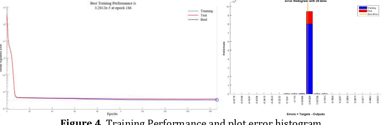
To estimate the stator flux, the FFNN should learn the behavior of the stator flux model under various conditions in order to obtain precise performance. Induction motor model is known from DC test, AC test, and no load test, block rotor test. In order to test the performance of the estimator, it was decided to estimate the stator flux to validate the feasibility of estimation. The FFNN stator flux estimator is developed from measurable motor parameters such as u u i ids, qs, , ,ds qs e. This simulation uses neural
network matlab toolbox, which is supported to supervise the learning proccess from nonlinearity complex model of the induction motor. System will be run in ideal condition to get the desired output signal. This data was record as data set. The data will be trained with several minutes to get the best performance and very small error. The training result shows the error histogram including training, test, and zero error parameter with 20 bins and the error histogram is used for additional verification of estimation performance.
Figure 4. Training Performance and plot error histogram
EMITTER International Journal of Engineering Technology, ISSN: 2443-1168
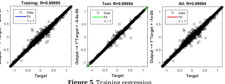
Figure 5. Training regression The final mean-squared error is about 3.2012e5
at epoch 186. In this case, the FFNN estimator response is satisfyed, so the FFNN model is put in the IM model to investigate the estimator response in another drive condition. To test the performance, the original input signal is presented and compared with actual value, adaptive compensation, amplitude limiter and FFNN flux estimator. The actual and estimated stator flux density is represented in Figure 6. Three algorithms are plotted on each other to illustrate the algorithm performance. The adaptive compensation and amplitude limiter allways make an overshood and undershoot. The error value is 3.2% and 5.42% respectively. The FFNN estimation produces the small error in steady state with error value is 0.742%, but when motor is in transient condition, the FFNN is less responsive to change command. Based on the result, for proposed accuracy estimation, the FFNN algorithm is recommended to be implemented.
Figure 6. Comparison of stator flux estimator
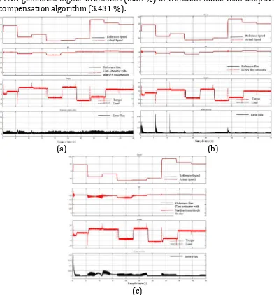
IM model is tested using 3 reference input — speed reference, stator flux reference, and torque load. These inputs are generated from a random number in which it is add with low uniform noise. The variety of each load can be observed by the characteristics of vector magnetic flux density and vector magnetic field intensity. It is very influential on hysteresis loop.
EMITTER International Journal of Engineering Technology, ISSN: 2443-1168 feedback in the closed loop PI speed regulation, related to (17). The result represents that a good speed response is in forward and reverse operation. The second trace shows the reference flux which is compared with flux estimator and the result views significant differences between three proposed methods. The electromagnetic torque produces high ripple and overshoot or undershoots in a transient condition and it is shown on torque trace. This simulation result substantiates the expected proposed performance. If we compare among three different algorithms, based on error flux trace, the adaptive compensation algorithm produces error deviation (0.0243 T) which is greater than FFNN algorithm (0.0102 T), but FFNN generates higher overshoot (6.82 %) in transient mode than adaptive compensation algorithm (3.431 %).
(a) (b)
(c)
Figure 7. (a) stator flux estimator with adaptive compensation, (b) stator flux with FFNN estimator, (c) stator flux estimator with integrator limiter.
EMITTER International Journal of Engineering Technology, ISSN: 2443-1168
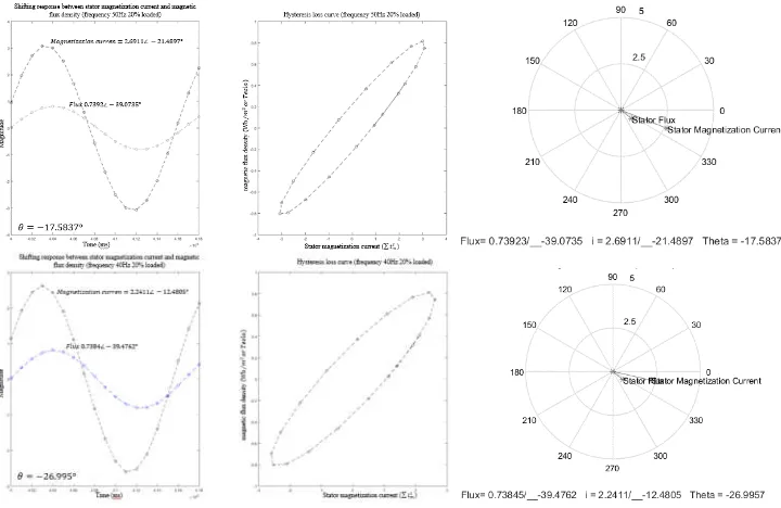
to the stationary frame of the rotational motor, causing the vector flux locus to be not a straight line, but an ellipse or any complex closed trajectory. Figure 8 shows the change in the hysteresis curve to the frequency change, . On other side Figure 9 shows the chage in the various loads. The results of this test supports the previous expression and look like identical with the results made by [27] and [28].
With variations in a load operation, induction motors produce higher magnetization currents at high load. Because of the phase difference between B and H caused by the rotational hysteresis effect, the phase difference can be represented in the vector diagram in Figure 8.
Figure 8. Stator flux and magnetizing current, with vector properties.
EMITTER International Journal of Engineering Technology, ISSN: 2443-1168
Figure 9. Hysteresis loss curve among various load
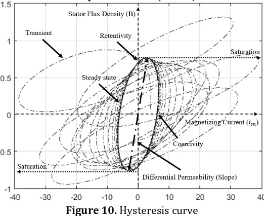
Based on Figure 10, the hysteresis loss curve are symmetrical about the plot center, although their shapes differ widely among the various loads. This curve includes all of possible stable and transient conditions that can be assumed by magnetizing force of an imposed field. From this figure, the retentivity is 0.74 T. This value is defined as a magnetic force which return the domains to their original zero-balance condition. once this balance has been set by an imposed saturating field. It is represented by intercept of the B-axis when the H is zero. In other side, when the curve is intercept of the H-axis when B is zero, the residual magnetism left in a saturating magnetic field has been removed. Its call coercivity with the value is 6,78 A/m2. In actuality,
the stator flux density continues to increase beyond saturation effect in (6). It is related to the maximum amound of B that can be forced through a material and various load of the magnetizing force.
Figure 10. Hysteresis curve
6. CONCLUSION
EMITTER International Journal of Engineering Technology, ISSN: 2443-1168
estimator, stator flux estimator with integrator limiter. The speed response, flux response, torque response and error deviation of flux estimator are presented in fig 6 and fig 7. The FFNN flux estimator gives a small error, precision value, but unresponsive for the transient mode. The adaptive compensation response is better then FFNN flux estimator for transient mode, but higher error value then FFNN flux estimator. By using the proposed model, the stator magnetizing current and stator magnetic flux density can be plotted to hysteresis curve. The result shows the response shifting signal and vector properties at an instantaneous time. The simulation performed shows hysteresis curve in the form of an ellipse curve, which is identic with another invention that has been published.
Acknowledgements
This work is supported by research group of Electric machinery control laboratory by the Politeknik Elektronika Negeri Surabaya, Surabaya, Indonesia.
REFERENCES
[1] "Global EV Outlook 2016, beyond one million electric cars," IEA, Paris, 2016.
[2] C. U. Paul Waide, "Energy Efficiency Policy Opportunities for Electric Motor-Driven System," International Energy Agency, France, 2011. [3] M. El-Hawary, Introduction to Electrical Power Systems, Canada: John
Wiley & Sons, 2008.
[4] A. khajepour, S. Fallah and A. Goodarzi, Electric and Hybrid Vehicles, Technologies, Modeling and Control: a Mechatronic Approach, United Kingdom: John Wiley & Sons Ltd, 2014.
[5] M. A. Jirdehi and A. Rezaei, "Parameters estimation of squirrel-cage induction motors using ANN and ANFIS," Alexandria Engineer Journal,
pp. 357-368, 2016.
[6] N. Jirasuwankul, "Simulation of energy efficiency improvement in induction motor drive by fuzzy logic based temperature compensation,"
in 3rd International Conference on Energy and Environment Research,
ICEER 2016, Barcelona, Spain, 2017.
[7] E. Purwanto, D. MW, Harianto, G. Prabowo and A. Rofig, "Simulation of The Apllication Fuzzy Logic Controller in 3 Phase Induction Motor Speed Control by Selectig Membership Fuction Parameter," in IEEE
TENCON'02, 2002.
[8] K. H. Nam, AC Motor Control and Electric Vehicle Applications, London, New York: CRC Press, Taylor & Francis Group, 2010.
EMITTER International Journal of Engineering Technology, ISSN: 2443-1168 Rotating Machines, Design, Evaluation, Aging, Testing, and Repair, New Jersey: John Wiley & Sons, Inc, 2014.
[10] K.-h. J.-J. J.-P. G.-H. Hyuk Nam, "A Study on Iron Loss Analysis Method Considering the Harmonics of the Flux Density Waveform Using Iron Loss Curve Tested on Epstein Sample," IEEE Transactions on Magnetics,
Vol 39. No. 3,, p. 1472, 2003.
[11] H. Yoon, M. Song, I. Kim, P. S. Shin and C. S. Koh, "Accuracy Improved Dynamic E&S Vector Hysteresis Model and its Application to Analysis of Iron Loss Distribution in a Three-Phase Induction Motor," IEEE
Transactions on Magnetics, vol. 48, no. 2, pp. 887-891, 2012.
[12] W. P. Curtiss, Winthrop and Mass.Cambridge Patent 4445080, 25 November 1981.
[13] M. Ranta, M. Hinkkanen, E. Dlala, A.-K. Rapo and J. Luomi, "Including of Hysteresis and Eddy Current Losses in Dynamic Induction Machines Models," in IEEE International Electric Machines and Drives Conference, Miami, USA, 2009.
[14] D. Buecherl and H.-G. Herzog, "Iron Loss Modeling by Complex Inductances for Steady State Simulation of Electrical Machines," in IEEE, International Symposium on Power Electronics, Electrical Drives,
Automation and Motion, Pisa, Italy, 2010.
[15] M. Oka and M. Enokizono, "Evaluation of Hysteresis Loss and Eddy Current Loss in Induction Motor Stator Cores Using the Excitation Inner Core Method," in International Conference on Electrical Machines (ICEM), IEEE, Lausanne, Switzerland, 2016.
[16] M. Enokizono, "How to Decrease Magnetic Power Loss for Development of High Efficiency Electric Machines," in IEEE, International Symposium
on Electrical Aparatus and Technologies (SIELA), Bourgas, Bulgaria,
2016.
[17] M. Enokizono and K. Okamato, "Designing a Low-Loss Induction Motor Considering the Vector Magnetic Propoerties," IEEE Transactions on
Magnetics, vol. 38, no. 2, pp. 877-881, 2002.
[18] N. Kunihiro, T. Todaka and M. Enokizono, "Loss Evaluation of an Induction Motor Model Core Considering Two-dimensional Vector Magnetic Properties," in IEEE International Conference on Electrical
Machines and Systens, Tokyo, Japan, 2009.
[19] T. Sato, T. Todaka and M. Enokizono, "Improvement of Integral-Type Dynamic E&S Modeling," in IEEE Electromagnetic Field Computation, Chicago, USA, 2010.
EMITTER International Journal of Engineering Technology, ISSN: 2443-1168
Machines and System, Seoul, South Korea, 2007.
[21] E. Purwanto, S. Yukihiko, M. Herry and G. Prabowo, "The Development of Speed Sensor Observer for Induction Motor by Using Adaptive Neuro Fuzzy with Back Propagation Learning Method," in IEEE 8th International Conference on Properties & Applications of Dielectric
Materials, Indonesia, 2006.
[22] R. T. Smith, Analysis of Electrical Machines, USA: Pergamon Press, 1982. [23] A. M. Trzynadlowski, Control of induction motor, Reno, Nevada:
Academic press, 2001.
[24] J. Hu and B. Wu, "New integration algorithms for estimating motor flux over a wide speed range," IEEE Transactions on Power Electronics, vol. 13, no. 5, pp. 969-977, 1998.
[25] M. Ranta, "Dynamic induction machine models including magnetic saturation and iron losses," Aalto University Publications, Finland, 2013. [26] B. K. Bose, Modern Power Electronics and AC drives, USA: Prentice Hall,
Inc., 2002.
[27] K. Saito, T. Sasayama and M. Nakano, "Measurement of hysteresis loop at the tip of the teeth of an inverter-driven squirrel-cage induction motor," Intermag, Japan, 2015.
[28] A. Pruksanubal , "Analysis of Squirrel-Cage Induction Motor Considering Hysteresis Loss of Magnetic Material," in Electrical Machines and System,
![Figure 3. Vector control drive with closed flux and speed loops-feedbacksolutions. For the first solution, the property of orthogonality of the stator EMF and flux vector uses an adaptive compensation [23]](https://thumb-ap.123doks.com/thumbv2/123dok/4040803.1984223/8.595.164.437.355.497/figure-vector-feedbacksolutions-solution-property-orthogonality-adaptive-compensation.webp)