A NUMBER OF VENTING HOLES DISC BRAKE IMPACT ON STATIONARY TEST
Ian Hardianto Siahaan
1), Ervin Edi Hermawan
2)Mechanical Engineering Department Petra Christian University 1,2)
Siwalankerto 121-131, Surabaya 60236. Indonesia 1,2) Phone: 0062-31-2983465, Fax: 0062-31-84176581,2)
E-mail :[email protected]
ABSTRACT
Braking system is very important element to control velocity of vehicle when it is working on the road. Braking system concept always follows principle of normal force which it is using friction force method for rubbing on lining pad of disc brake. Braking system must able to overcome circumstances when working on high level of velocity and stopping on safe circumstances. In this research field orientation, a number of disc brake with sum of different venting holes are being tested by giving variable of velocity from 20 to 80 km/hours and being interfaced by different braking pressure (4 to 6 kg) on lining pad of disc brake on stationary test. In conclusion, the results show 24 venting holes which have been giving effective performing amongst all of the other of venting holes. Similar to other of venting holes with pertaining velocity of vehicle and braked pressure can be explained clearly with significant chart when it is going to develop by interfacing control system for finding effective stopping time especially when brake pad of disc brake will be produced in manufacturing process as product consideration.
Keywords: venting holes, disc brake, stationary test, braking system, number.
1. Introduction
Braking system is important element which relating to human safety factor when riding a vehicle on the road. Braking is defined as an element which has purpose to decline velocity of vehicle or to stop mechanical movement. According to Greek, it is called “Frein” and “Rem” in Indonesian language which refers to Netherlands language. Generally, braking system is designed to overcome velocity of vehicle when it is conducting for turning movement and for stopping velocity of vehicle. Most of vehicles have complexity of braking that they are either combined by hydraulics system, vacuum, electrical or mechanical system. When the brake pedal is pressed the force is amplified using a lever. From there a vacuum generated from the engine is used to assist the brake pedal motion. That motion is transferred through hydraulic fluid in all directions until it reach the braking unit on each wheel. This complex configuration can be simplified and improved using brake by wire. A driver should be easy to use braking system for declining velocity of vehicle by giving warning system to solve braking problem fast. According to Mr.Rahardjo Tirtoatmodjo who explain of braking standard must involve high speed stopping at maximum velocity 100 mph (161km/hour) without skidding when brake pedal is being pressed at 200 lb (890 N). Braking system must be also tested either in wearing circumstances, in the road with full of water or when parts of its system is being devastated. Real braking test should be tested either in winter or dry season to know its performance. Braking system also should be dry fast when passing either in wet road or ashy road to maintain braking ability operate well.
On this paper, disc brake is limited to one circumstance from some of treatments that have been explained previously with many circumstances. Similar to previous explanation that on this paper is only done by stationary test to know accuracy of impact number of venting holes which being related to stopping time. There are some parameters that they are used or this stationary test i.e.: stopping time, braking load or pressurized loading, and velocity of vehicle.
Performance of disc brake depends on thickness of brake pads and it must be not less 1 mm. Disc brake uses a new homogenous brake pad on stationary test which is higher thickness than standard to ease experimentation results without considering thickness of brake pads. There are some types of motor cycle disc brake that can be showed on this below figure and encountered in market places:
2. Theory of Background
To get effective braking from a number of venting holes is a purpose of this paper. There are two circumstances which are causing circumstances, i.e.: skidding and not skidding. Skidding is defined by multiplying force which pressing either caliper, brake pads, pistons, valve or actuator of hydraulic system with radius of disc brake. Generally, transmission force will rise over three times of master cylinder pressure. Disc brake has low temperature velocity which is used to distribute heat energy as result of friction force. Even disc brake has advantage, but also has disadvantage for instance ashy from circumstance which enter opened construction of disc brake. Sometimes, ashy from road makes disturbance so that brake pad is getting worse which making brake pad become weary circumstances. If rotor is thinner and thinner, then it will not give effective for gripping of the rotor. Braking system uses friction force to retard velocity of vehicle when brake pedal is activated. Friction force is an ability of object against surface from sliding. When an object is sliding against steady surface or remained space shows that a force is working on the object.
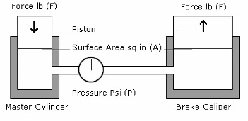
On disc brake, there is external pressure which is appeared by braking pressure on wall surface of brake caliper and piston caliper. Friction force that would be being happen is piston force which is multiplied by friction force of brake pad. Operational hydraulic system is based on Pascal Law. Pascal says that fluid will spread in all directions with equal force. Principle of disc brake is used to access on its accessing. Pressure is given against brake oil in closed loop which is continued in all directions by giving equal pressure. Braking system should have master cylinder, ball cylinder, hydraulic valve which has abilities to change, to keep, to delay, and to compare external pressure. Generally, channel of oil brake is a flexible channel for joining master cylinder to wheel cylinder.
Figure 2. Principle of Motorcycle Brake Systems
Furthermore, force is calculated by multiplying pressure with piston area. It is simplified by equation below:
F = P/A (1)
Due to equation (1), balance system for the principle of brake system can be simplified by equation:
(Weight 1/ weight 2) = (Surface area1)/( Surface area 2) (2)
Or:
(Weight 1/ weight 2) = (Distance of area1 moving decline)/( distance of area 2 moving rise) (3)
Derived from equation (3) is simplified by formulation,
W1 x S1 = W2 x S2 (4)
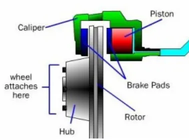
Figure 3. Disc Brake Mechanism
Friction force on the disc brake will decline velocity of vehicle. Surface friction of brake pad and disc have friction force that have equal force. Force which is working to decline vehicle of velocity, really it is happened on thread of tire. Size of disc brake is smaller than wheel diameter which shows appropriate diameter of tire to disc brake. To calculate friction force which support rotor, i.e.:
Rotor Friction Force = F x µ x 2 (surface friction) (5)
Whereas:
F = Activated force which is generated by oil pressure on caliper piston (N) µ = Coefficient of friction
In addition, friction force which happen apparently between thread of tire and disc brake is calculated by equation 6,
Friction Force = Rotor Friction Force x (Disc brake diameter/ Thread of tire diameter) (6)
3. Research Methodology
On stationary test, there are two steps which supporting for this experiment. First step is to provide for tools and materials to support for stationary test. Second step is to fill in worksheets data to analyze influence of a number venting holes which are working.
For providing tools and material will follow the instruction, i.e.:
• Preparing motor cycle which supports stationary test
• Fixing disc brake 24-venting holes, 32-venting holes and 42-venting holes at motorcycle • Preparing pen, worksheet paper, stopwatch, weight
• Adjusted a roller wheel of selected motorcycle
For filling up worksheet data will follow the instructional test, i.e.:
• Preparing for setting motorcycle position that have been put it on the roller at rear wheel which selects of
velocity on it, respectively : 20 km/h, 40 km/h, 60 km/h and 80 km/h.
• After giving the weights are according to appropriate velocity by falling down the loads respectively: 4 kg, 5 kg, and 6 kg.
• Three times for taking test parameters for evaluating results when the rear motorcycles have been stopped.
Statistical method is applied to accommodate faults result during processing test
• Writing down the results of test on paper as results of braking performance during test.
Tools and materials that used on stationary test, i.e.:
Figure 4. Supported Roller
• Motorcycle, for testing experiment is used Supra X in good condition including excellent performance for
getting the results. This motorcycle is selected because every people uses this type and their parts are easy to find in market places. It is the best characteristic why this paper chooses this motorcycle and scheduling maintenance system is easy to adjust in anytime that it is used by adjuster.
Figure 5.Supra X 125 R
• Weighting Scale, for testing experiment technique is used as braking load against to brake pedal. To give each weights is important to know stopping time during the load have been giving during the tests. Braking distance can be counted by physics formulation after each clear test time.
• Disc brake, 24- venting holes
Figure 7. 24-Venting Holes
• Disc brake, 32- venting holes
Figure 8. 32-Venting Holes
• Disc brake, 40- venting holes
The three types of disc brake with different venting holes should have the equal material properties for testing evaluation so that the results could be approximated significantly.
4. Result and Discussion
There are three recapitulation graphs which explain about the impact of a number venting holes by interfacing different braking load on brake pad.
Firstly, the data illustrates the impact of a number of venting holes by giving pressure load 4 kg at different velocities. The graph shows stopping time data as a result of different number venting holes. Braking performance of 24 venting holes is shown that stopping time is better than others. Stopping distance rises while velocity increases at equal conditions. Similarly, stopping distance of 32 venting holes and 40 venting holes rises during increasing of velocity.
Figure 10. Velocity Vs Stopping Time
Secondly, the data illustrates the impact of a number of venting holes by giving pressure load 5 kg at different velocities. The graph also shows stopping time data as results of different number venting holes. Braking performance of 24 venting holes is still shorter than 32 and 40 venting holes
Figure 11. Velocity Vs Stopping Time
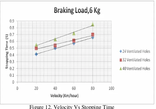
Figure 12. Velocity Vs Stopping Time
Finally, 24-venting holes shows a shorter time to stop vehicle even by increasing of braking load than the other of venting holes. According to the hypothesis that sum of venting holes determine the ability of vehicle to control well.
5. Conclusion
On this paper shows that sum of venting holes have some impacts for filling up the choice of braking performance.
• Disc brake with 24 venting holes has a shorter time to stop or to decrease stopping time.
• Increasing of velocity gives higher stopping distance during stationary test
• To give effective braking system will choose the lowest sum of venting holes in market place to decline stopping time.
• Human safety factor will be being increasing when riding motor cycle with a small sum of venting holes.
• Increasing of braking load influences stopping time.
• For safety riding will be better to fix motorcycle with lower sum of venting holes and by decreasing velocity of vehicle with higher braking load.
Reference:
1. Crouse, William,”Automotive Mechanics”, The Drayden Press, USA 1993. 2. Northop,R.S.,“Teknik Reparasi Sepeda Motor” ,Pustaka Setia, Bandung, 2004. 3. Owen, Clifton ,”Automotive Brake System”, Haynes, North America, California, 2004. 4. Sutantra , I.N,” Teknologi Otomotif, Teori dan Aplikasinya”, Guna Widya, Surabaya, 2001
5. Albert, Christian,”Pengaruh Perubahan Diameter Lubang Ventilasi Pada Pringan Cakram Terhadap Jarak Penegereman Pada Pengujian Stasioner,”UK Petra,Surabaya,2009
6. Budynas.G Richard,” Shigley’s Mechanical Engineering Design”, (8th ed) New York Mc Graw Hill, 2004 7. Sularso, dan Suga,Kiyokatsu,”DasarPerencanaandan Pemilihan Element”, Jakarta, PT Pradya Paramita 8. Hermawan, Ervin Edi,”Pengaruh Jumlah Lubang Ventilasi Lingkaran Untuk Rem Cakram Pada Pengujian