ScienceDirect
Procedia Engineering 00 (2017) 000–000
www.elsevier.com/locate/procedia
1877-7058 © 2017 The Authors. Published by Elsevier Ltd.
Peer-review under responsibility of the organizing committee of SCESCM 2016.
Sustainable Civil Engineering Structures and Construction Materials, SCESCM 2016
Revitalization of Cracked Flexural Members using Retrofitting and
Synthetic Wrapping
Sri Tudjono
a, Han Ay Lie
a,*, Buntara Sthenly Gan
baDepartment of Civil Engineering, Diponegoro University,Prof Soedharto Street, Semarang 50239, Indonesia bDepartment of Architecture College of Engineering, Nihon University, Fukushima Prefecture, Koriyama 9638642, Japan
Abstract
The modification of the Indonesia earthquake code SNI 2002 to SNI 2012 resulted in a significantly higher performance demand. The basics of these amendments lay in the re-zoning of earthquake maps, and the consideration of the earthquake influence to gravity loads. Members designed based on the SNI 2002 most likely will result in failure under future earthquakes. A reinforcement method based on the ACI 440 provision was conducted on cracked flexural members. The tensile reinforcement of these members has yielded and was neglected in the design. The tensile strains and stresses were further carried by the synthetic wraps applied to the tensile concrete fibers. The shear capacity of the member was enhanced by confinement of the member using the same synthetic wrap. Prior to wrap application, the members were straightened and retrofitted with an epoxy resin injection. The member was tested using a one-point-loading system to simulate a maximum bending moment in combination with maximum shear forces. The load-displacement responses and the ultimate load carrying capacity under monotonic incremental loading were recorded. It was found that this method will provide a solution for revitalization of cracked members in bending, and offer a solution to the design code alterations.
© 2017 The Authors. Published by Elsevier Ltd.
Peer-review under responsibility of the organizing committee of SCESCM 2016.
Keywords: synthetic shear and tensile reinforcement, retrofitting, ultimate load
* Corresponding author. Tel.: +62-811288313; fax: +62-24-76480727
1.Introduction
Concrete beams as members of a rigid framework are widely used, since the structure has a very high gravity load carrying capacity in combination with a good performance for resisting horizontal responses.
The introduction of the new 2012 building code implies significant changes to the design of concrete frames. A modification among others is the re-mapping of earthquake zoning, intensifying the majority of spectrum responses. The new code also introduces the seismic design criteria taking into consideration the soil conditions, building function and configuration, leading to a classification of structural building types. These criteria were not covered in the previous code. Another topic covered by the new code was the storey-drift design criteria, which is now very comprehensive and explanatory. However, the most notable revision is the amplification from a 500 years, to 2500 years’ return period. All these changes resulted in a significant horizontal load enhancement, demanding a much higher load-carrying capacity and performance of a member in flexure.
A previous study [1] proposed the concept of externally reinforcing a concrete T-section designed based on the 2002 code, advancing the section to the 2012 standard. The method chosen was by applying externally bonded tensile reinforcements in combination with shear confinement based on the ACI 440.2R-08 [2]. Non-directional woven carbon fibers bonded to the concrete surface by a polymer resin were utilized. The carbon fibers had a
Young’s modulus of 230 GPa and an ultimate tensile strength of 3500 MPa. The impregnated carbon fibers had a
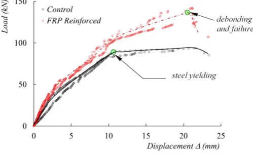
tensile strength of 750 MPa in combination with a Young’s modulus of 55 GPa. The proposed method resulted in a 44% moment capacity increase and the reinforced section met the demands of the code (Fig. 1).
Fig. 1. load-displacement responses of FRP and non-FRP sections (Tudjono et al., 2015).
The control specimen, having no FRP reinforcement, failed due to yielding of the steel reinforcements in tension. The load-displacement response subsequent to yielding, exhibited a clear yield plateau. The strains in the tensile reinforcement ranged from 0.004 to 0.010. The loading was concluded, and visual observation revealed that the steel bars indeed had yielded, but remained unbroken. As for the externally FRP reinforced members, it was found that
the beam’s failure mode was due to de-bonding at the interface between the carbon fibers and the concrete in tension. These concrete fibers cracked, and the cracks propagated vertically toward the neural axis of the beam. Further, the steel reinforcement rapidly yielded since the bond of the FRP prior to de-bonding delayed the failure process, resulting in a sudden collapsing of the beam. The outcome of the study implied that a better bond could improve the capacity of the section.
2.Retrofitting and FRP reinforcements
2.1.Retrofitting
Retrofitting has been one of the chosen methods for revitalizing cracked concrete sections. A range of methods and retrofitting agents were proposed in the past few years [7, 8, 8, 9, 10, 11]. The approach favored in this study was by injecting the cracks using a low viscosity epoxy resin having a centiPoise (cps) of 180. The agent has a bond strength of 20 kg/cm2 at the age of 28 days, in combination with a 64 MPa compressive strength which is substantially higher than the 45 MPa cylindrical compression strength of the beam.
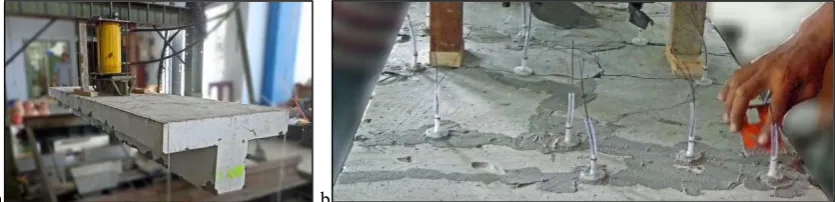
The bended section was firstly straightened mechanically by applying a counter load to the member (Fig. 2a). The process was monitored carefully and the member’s surface condition controlled by a water-level. The surface and cracks were cleaned mechanically by grinding, followed by brushing and vacuuming. Packers were inserted into the cracks with a distance of approximately 10 centimeters. A steel nail was then placed through the packer into the crack, preventing blockage of the injection canal when the sealant agent was applied (Fig. 2b). The concrete surface between the packers was securely sealed. The nail was removed upon curing of the sealant, and the injection process was started. The injection was continued until the resin flowed from the second packer, nearest to the first one. The process was continued to the next packer. The resin was cured for 28 days:
a b
Fig. 2. retrofitting (a) straightening; (b) packer placement and sealing.
2.2.FRP reinforcement
a b
Fig. 3. (a) surface treatment by grooving; (b) application resin and FRP.
The study on the surface preparation influence was utilized a 50 mm long bond area, which was very close to the minimum development length for shear transfer [12, 13, 14, 15, 16]. For the existing members, a much longer transfer length was obtained since the carbon fibers were placed over the entire length of the beam.
3.Test results
3.1.Failure mode
A monotonic load increment of 120 N/sec was applied, and the deformation recorded. The concrete layers in extreme tension and compression were monitored using strain gauges, while the FRP response was measured near
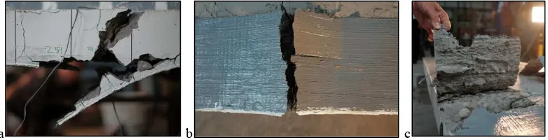
the support, and at a distance of ¼ of the beam’s length. Both the test specimens failed due to failure in the FRP
sheets as can be seen in Fig. 4a and 4b. The bond in the interface was strong enough to transfer the shear stresses and strains from the concrete to the FRP. At the next stage, the concrete in the bond area collapsed to the high shear stresses adjacent to the interface (Fig. 4c).
a b c
Fig. 4. (a) FRP tensile failure; (b) FRP tensile failure; (c) concrete shear failure in the bond area.
3.2.Load-displacement responses
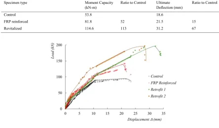
Since the steel reinforcement had previously not reached its optimum strain during testing, the beams exhibited a ductile behavior that was observed from the significant deformations at failure, as shown in Fig. 5.
The revitalized member had an almost identical initial stiffness to both the control and the FRP reinforced element, and at advanced loading stages the revitalized element exhibited a higher structural stiffness as compared to the control element without the carbon sheets. The pattern of the load-displacement path resembled the FRP specimens, and no yield plateau was observed, underlining that the steel reinforcements had yielded prior to testing. The two test specimens reached an ultimate load of approximately 200 kN, and the behavior was characterized by large deformations of the beam. Table 1 shows a comparison of moment capacity and ultimate deflection for the three cases.
Table 1. Control, FRP and revitalized member comparison.
Specimen type Moment Capacity
(kN-m)
Ratio to Control Ultimate Deflection (mm)
Ratio to Control
Control 53.8 18.6
FRP reinforced 81.8 52 21.5 15
Revitalized 114.6 113 31.2 67
Fig. 5. load-displacement comparison.
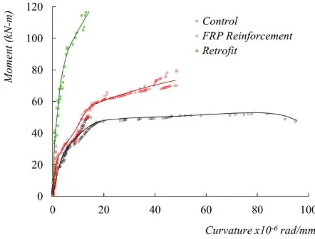
3.3.Moment-curvature responses
Fig. 6. moment-curvature comparison.
The retrofitted element had the smallest relative curvature with respect to the section’s moment. The control
element was the most rigid, but showed a clear yielding path, consisting of an increase in curvature at a constant moment. The FRP member had a gradually descending moment-curvature response, suggesting that the bond in the FRP steadily declined, allowing the tensile steel reinforcement to yield. The retrofitted specimen had a constant but very small increase in curvature.
4.Analysis and conclusions
The application of carbon fibers on a T-section resulted in an enhancement of 52% in moment capacity, while the ductility of the member benefited 15%. The results were considered not optimum, since failure occurred due to de-bonding in the FRP-to-concrete bond sheets in tension.
To analyze the feasibility of revitalizing a cracked section, the retrofit-injection method was applied to the cracked member. Since tensile reinforcements have yielded, the carbon fiber sheets, applied in the same manner as was done with the FRP test specimen, functioned as tensile reinforcement. To increase the performance, the concrete surface was carefully prepared to exclude de-bonding in the interface between the carbon sheets and the concrete. The revitalized beam was subjected to a monotonic load, applied at the midpoint, representing a negative bending moment in combination with maximum shear stresses. It was shown that the revitalized member failed due to rupture of the carbon sheets in tension. The method of surface preparation prior to FRP application enhanced the bond. The moment capacity of the section and the ductility of the beam were influenced positively by the combination of retrofitting, FRP application and surface treatment improvements.
The increase in load-carrying capacity is explained as follows. The improvement in FRP-to-concrete bond did, as
expected, enhance the member’s capacity resulting in an impeccable transfer of tensile stresses from the concrete to
the FRP. The steel reinforcement had a permanent strain of 0.004 to 0.018, originating from the previous loading, emphasizing that the tensile reinforcement had yielded. The load-carrying capacity of the revitalized member was a contribution of the concrete in compression, the FRP in tension, and strain hardening of the reinforcing steel. Additionally, the bond in the FRP-to-concrete interface also provided a restrain in the tensile direction of the concrete fibers, delaying cracking of the material. Softening of the specimen was detected in the postpeak-branch of the load-displacement curves. Similar findings were reported based on both experimental and numerical studies [17, 18].
The retrofitting material thus indirectly enhanced the tensile strength of the member. Studies on the impact of retrofitting concrete frames [19] underlined the enhancement of shear performance in particular.
The result of this research work provides a solution to overcome the failure of flexural elements due to increasing horizontal loads. It cannot be stated with certainty as to what extent the retrofitting increased the moment capacity and ductility; however, the improvement in FRP-to-concrete bond contributed significantly to the performance of the beam. A comparison study to evaluate the behavior of an un-cracked beam element with a perfect bond needs to be conducted, to determine the contribution of the improved bond alone. The standards and codes should therefore strengthen the necessity of a good surface preparation prior to application of synthetic wraps and sheet. It was also shown that the guidelines as provide by the producer of the product are not sufficiently enough to prevent de-bonding in the interface.
In the new SNI 2012 design code, due to re-zoning of the earthquake maps and considerations its influence to gravity loads, higher performance of structural member’s design is demanded. Present works demonstrated that reinforcing and retrofitting cracked beams using FRP sheets following the ACI 440 provision, could result in exceeding the strength requirements as amended by the new SNI 2012 code.
References
[1] S. Tudjono., Han A.L, A.B. Hidayat, An Experimental Study to the Influence of Fiber Reinforced Polymer (FRP) Confinement on Beams Subjected to Bending and Shear, Procedia Engineering, Vol. 125, 2015, pp. 1070-1075.
[2] T. Triantafillou, C. Antonopoulos, Design of Concrete Flexural Members Strengthened in Shear with FRP. J. Compos. Constr., Vol.4, issue. 4, 2000, pp. 198-205.
[3] D. Kachlakev, D.D. McCurry, Behavior of full-scale reinforced concrete beams retrofitted for shear and flexural with FRP laminates, Composites Part B: Engineering. Vol. 31, issue. 2000, pp. 445–452.
[4] C.S. Ravikumar, T.S. Thandavamoorthy, Application of FRP for Strengthening and Retrofitting of Civil Engineering Structures”, International Journal of Civil, Structural, Environmental and Infrastructure Engineering Research and Development (IJCSEIERD), Vol. 4, 2014, pp. 49-60.
[5] S. Tudjono, Han A.L, A. Hidayat, Purwanto, Experimental Study on the Concrete Surface Preparation Influence to the Tensile and Shear Bond Strength of Synthetic Wraps, Submitted to the 3rd SCESCM Conference in Bali September 2016.
[6] C.K.Y. Leung, FRP debonding from a concrete substrate: Some recent findings against conventional belief, Cement & Concrete Composites Vol. 28, 2006, pp. 742-748.
[7] F. Alaee, B. Karihaloo , Retrofitting of Reinforced Concrete Beams with CARDIFRC, J. Compos. Constr., Vol. 7, issue. 3, 2003, pp.174-186. [8] Y.T. Obaidat , Structural Retrofitting of reinforced concrete beams using carbon fibre reinforced polymers dissertation, Lund University, 2010 [9] Y.T. Obaidat, S. Heyden, O. Dahlblom, G. Abu-Farsakh. Y. Abdel-Jawad, Retrofitting of reinforced concrete beams using composite
laminates, Construction and Building Materials, Vol. 25, issue. 2, 2011, pp. 591-597
[10] E.E. Zghayar, K. Mackie,J. Xia, Fiber Reinforced Polymer (FRP) Composites in Retrofitting of Concrete Structures: Polyurethane Systems Versus Epoxy Systems, ACI Special Publication 298, 2014, pp. 1-22.
[11] M.A.A. Aldahdooh, N.M. Bunnori, M.A.M. Johari, A. Jamrah, A. Alnuaimi, Retrofitting of damaged reinforced concrete beams with a new green cementitious composites material. Composite Structures, Vol. 142, issue. 10, 2016, pp. 27-34.
[12] T. Mohammadi, Failure Mechanisms and Key Parameters of FRP Debonding from Cracked Concrete Beams, Ph.D Thesis, Marquette University, Milwaukee, Wisconsin, 2014.
[13] T.H.K. Kang, J. Howell, S. Kim, D.J. Lee, A State-of-the-Art Review on Debonding Failures of FRP Laminates Externally Adhered to Concrete, International Journal of Concrete Structures and Materials, Vol.6, issue.2, 2012, pp.123–134.
[14] I. Akbar, D.J. Oehlers, M.S.M. Ali, Derivation of the bond-slip characteristics for FRP plated steel members, Journal of Constructional Steel Research Vol. 66, 2010, pp.1047-1056.
[15] O. Buyukozturk, O. Gunes, E. Karaca, Progress on understanding debonding problems in reinforced concrete and steel members strengthened using FRP composites, Construction and Building Materials. Vol. 18, Issue 1, 2004, pp. 9–19.
[16] C. Leung, Delamination Failure in Concrete Beams Retrofitted with a Bonded Plate, J. Mater. Civ. Eng., Vol.13, issue 2, 2001, pp. 106-113. Special Section: Fracture Mechanics in Concrete Repair/Strengthening.
[17] O. Buyukozturk, B. Hearing, Failure Behavior of Precracked Concrete Beams Retrofitted with FRP., Journal of Composites for Construction, Vol. 2, issue 3, 1998, pp. 138-144.
[18] Y.T. Obaidat, S. Heyden, O. Dahlblom, The effect of CFRP and CFRP/concrete interface models when modelling retrofitted RC beams with FEM, Composite Structures. Vol. 92, Issue 6, 2010, pp. 1391–1398.