HEIGHT GRADIENT APPROACH FOR OCCLUSION DETECTION IN UAV IMAGERY
H. C. Oliveira a, A. F. Habib b, A. P. Dal Poz c, M. Galo c
a São Paulo State University, Graduate Program in Cartographic Sciences, Presidente Prudente, Brazil
b Purdue University, Lyles School of Civil Engineering, West Lafayette, Indiana, USA - [email protected] c São Paulo State University, Dept. of Cartography - (aluir, galo)@fct.unesp.br
KEY WORDS: UAV, DSM, TIN, Double Mapping, Height Gradient, Occlusion Detection, True Orthophoto
ABSTRACT:
The use of Unmanned Aerial Vehicle (UAV) significantly increased in the last years. It is used for several different applications, such as mapping, publicity, security, natural disasters assistance, environmental monitoring, 3D building model generation, cadastral survey, etc. The imagery obtained by this kind of system has a great potential. To use these images in true orthophoto generation projects related to urban scenes or areas where buildings are present, it is important to consider the occlusion caused by surface height variation, platform attitude, and perspective projection. Occlusions in UAV imagery are usually larger than in conventional airborne dataset due to the low-altitude and excessive change in orientation due to the low-weight and wind effects during the flight mission. Therefore, this paper presents a method for occlusion detection together with some obtained results for images acquired by a UAV platform. The proposed method shows potential in occlusion detection and true orthophoto generation.
1. INTRODUCTION
The use of images to support engineering projects has been employed for decades. Most of the projects need geospatial information with high level of accuracy. Regarding this requirement, a product called orthophoto is widely used. The orthophoto is geometrically equivalent to a line map; in other words, it is possible to measure distances, angles and areas correctly, using an image that contains a high level of semantic information (Wolf and Dewitt, 2000).
To generate the orthophoto, it is necessary to have a digital representation of the surface, the Exterior Orientation Parameters (EOP) of the platform, and the Interior Orientation Parameters (IOP) of the camera. These elements allow the correction of the relief displacement and the platform attitude effects over the original images. Usually, in the orthophoto generation process (orthorectification), a Digital Terrain Model (DTM) is used to represent the surface, despite the fact that this model only contains information about the terrain. As consequence, objects as buildings will not appear in a true orthographic projection. In such case, as for example projects executed in urban areas, a different model must be used. Thus, a Digital Surface Model (DSM) is utilized, which contains the terrain as well as all elements located above ground, such as buildings, trees, cars, etc. Even when using a DSM in the orthorectification process, an artifact denoted as “double mapping” (also known as “ghost image” effect) will take place. In these duplicated areas, one part is the correct roof position and the other represents its “ghost image” that hides some features/objects on the terrain level (see Figure 1 and 2). The region where the object is hidden by one building, or any other higher object, is the occlusion area induced by the relief-displacement effect and camera attitude.
For most applications, it is important to represent the elements above the ground in their correct orthogonal position and remove the ghost images within the occluded areas. After the occlusion detection, these regions can be filled with radiometric information from adjacent images. The product
that correctly places all building in orthogonal position without the double mapping effect is known as true orthophoto. Therefore, the greatest challenge for true orthophoto generation is the automatic occlusion detection followed by the search for radiometric information from adjacent images with the proper mosaicking procedure, including the radiometric compensation.
Nowadays, the use of UAV platforms can be seen as one interesting data acquisition alternative in many applications, such as mapping, environmental projects, feature extraction, 3D point cloud generation, and others. Some of these applications involve urban environments where buildings are present. The flying height of UAV systems are much lower than conventional airborne platforms, and as a result, the occlusion areas become bigger and the displacement of building position can be quite large. Thus, occlusion detection is a key issue when using images acquired from low-altitude UAV platforms for true orthophoto generation.
The main objective of this work is to present an alternative approach for occlusion detection using UAV images. We also present and discuss a true orthophoto result obtained considering the occluded areas identified by the proposed method.
This paper is organized as follows: Section 2 presents the definitions and fundamental elements for the orthorectification process, including the proposed method; Section 3 presents and discusses results regarding the occlusion detection and true orthophoto generation; the last section presents the conclusion based on the obtained results and some considerations for future work.
2. ORTHORECTIFICATION OF IMAGES
Orthophotos are used as a base-mapping product for taking decisions. The process to create an orthophoto is called orthorectification, that can be solved by direct or indirect methods (Mikhail et al., 2001) by using a DTM. This procedure aims at the removal of distortions due to platform
attitude and relief displacement during the image acquisition. These distortions become more severe when using UAV systems. Another product is the true orthophoto, created by the same principle but generated using a DSM, aiming at one product in which all objects in the scene are in a true orthogonal projection over the datum surface. Though, this section will describe the necessary elements to create a true orthophoto, which considers all the surface objects, and consequently, the requirement of an extra step: the occlusion detection.
2.1 Orientation Parameters
The aim of photogrammetry is to extract 3D information from a 2D dataset (images). However, to obtain results with high accuracy, the interior and exterior orientation parameters must be known with a good quality level.
The IOP define the camera characteristics necessary to reconstruct the object space bundle of rays from the points in the image space (Mikhail et al., 2001), and these parameters are obtained through a camera calibration process. It is important to have an accurate set of IOP when using UAV platforms.
The EOP characterize the position and orientation of the platform during the image acquisition epochs, i. e., the position and orientation of the bundle of rays with respect to the object space coordinates (Mikhail et al., 2001). For UAV systems, which are used to quickly survey small areas, a direct geo-referencing system is used. The direct geo-geo-referencing system allows the determination of the position by using a Global Navigation Satellite System (GNSS) receiver, and an Inertial Measurement Unit (IMU) to derive the attitudes. Nowadays the use of a Real Time Kinematic (RTK) system together with GNSS receivers allows for the derivation of good and fast results, as presented by Rieke et al. (2011) and Stempfhuber and Buchholz (2011).
2.2 Digital Surface Model
The orthorectification process needs a surface representation - DSM. This representation can be obtained using different techniques, such as: LiDAR systems (Light Detection And Ranging), RADAR systems (Radio Detection And Ranging), topographic surveys or photogrammetric techniques.
Since UAV systems allow to obtain very high-resolution images with good orientation parameters, one alternative to obtain an accurate DSM is by Dense Image Matching (Gruen, 2012). Some algorithms, for example the Semi-Global Matching (SGM) - Hirschmüller (2008) and Vertical Line Locus (VLL) - Paparoditis et al. (2000), can be applied for DSM generation.
2.3 Double Mapping
To project all objects that appear in one image in the correct orthogonal position, it is necessary to use a DSM. However, depending on how these points are projected, this process will create an effect called double mapping. The double mapping occurs due to the competition of different DSM cells for the same image pixel, during the orthophoto generation (Habib et al., 2007). This competition results in a double projection of buildings’ roof in the orthophoto, as can be seen in Figure 1.
Figure 1. DSM cells competition for the same image pixel – double mapping. Adapted from Habib et al. (2007).
Figure 1 shows one radial direction and as can be observed, the ground points D, E, F and the roof points A, B, C correspond to the image points a, b, c, respectively. The result of the double mapping for a portion of an image can be seen in Figure 2.
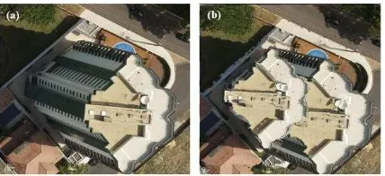
Figure 2. (a) The original image. (b) Double mapping effect.
As can be realized by this figure, the double mapping effect contains the real orthogonal position of the object and the displaced one.
2.4 Occlusion Detection
Existing approaches for occlusion detection include the Z-buffer (Amhar et al., 1998), Angle-based (Habib et al., 2007), Projective (Wang and Xie, 2012), and the Height-based (Oliveira and Galo, 2013) methods. All of these approaches analyze the visibility of a specific surface point in a given image. The main difference among the occlusion detection methods is the metric applied for identifying the occlusion areas.
The Z-buffer approach compares distances between the Perspective Center (PC) and the DSM cells that are competing for the same image pixel - the closest DSM cell is labelled as visible. The Angle-based method analyzes sequentially the off-nadir angles of the straight line formed by the PC and the DSM cell in a radial direction starting from the nadir point - sudden decrease of the angles indicates an occluded cell. The Height-based method analyses the height gradient computed in radial direction, also starting from the nadir point - negative height-gradient above a threshold indicates the beginning of one occlusion in this direction. The end of occlusion can be estimated from the intersection between the gridded DSM and the line passing through the perspective center and the beginning of occlusion. The Projective method uses a Digital Building Model (DBM), which is a 3D representation of all the buildings above the ground, to project the roof’s edges into the terrain surface and then identify the beginning and end of occlusion, and consequently the occlusion area.
However, these methods present some drawbacks. For example, the use of a DBM demands a significant pre-processing effort to have such a product. The Z-buffer method introduces false visibilities and occlusions that result from a situation where there is a difference between DSM cell size and Ground Sample Distance (GSD) of the image. The same false visibility can appear in regions with high and narrow buildings (Habib et al., 2007). All these methods require a gridded DSM as input information, which must be created by an interpolation process that might introduce errors. Another characteristic of these methods is the necessity of analyzing all DSM cells for occlusion detection.
Considering the context of orthophoto generation from images obtained by UAV it is possible to mention the work of Barazzetti et al (2014) in which the authors perform the visibility based in the analysis of occluded and occluding triangles with some strategy to reduce the CPU time.
2.4.1 Height Gradient Method
Considering these drawbacks, the objective of this research is to introduce the Height Gradient Method (HGM) as an alternative for occlusion detection using a dataset captured by a UAV platform.
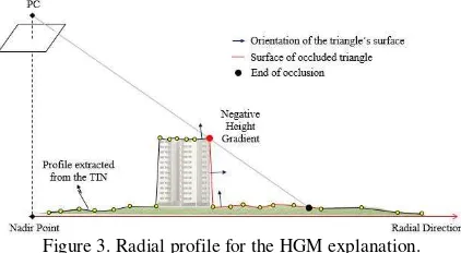
In the HGM, an input DSM is represented by a Triangular Irregular Network (TIN), which can be generated from the Delaunay constraint. Assuming that the TIN is available for the input image, for each radial direction of the image (starting from the nadir point), a profile using the elevation from the TIN is created, as shown in Figure 3. The profile elements contain the information of altitude and surface orientation, which allow the determination of variations in the height gradients and orientation of the triangles. When the height gradient is negative and an abrupt change in the triangle’s orientation is observed, it indicates a beginning of an occlusion area – this is the key point for the HGM. As soon as the beginning of the occlusion is identified, it is possible to consider its extent. The end of occlusion is the triangle that is intercepted by the straight line passing through the PC and the point that represents the negative gradient (red point in the Fig. 3). During this process, all triangles that are located between the beginning and the end of an occlusion are labelled as occluded. After sweeping all radial directions, the TIN will have new information concerning the visibility of the triangles in this image. These occluded triangles are used to seek radiometric information in adjacent images, and finally it is possible to generate a true orthophoto.
Figure 3. Radial profile for the HGM explanation.
The presented method (HGM) has some advantages when compared to the Z-buffer, Angle-based, Height-based, and Projective methods. The main advantage is the ability of using an irregularly sampled point cloud, instead of using a gridded DSM. It avoids artifacts that can be produced by the interpolation methods during the gridded DSM generation, and it is possible to consider different DSM densities in the area of the project. The HGM uses the surface orientation and height gradient variation to identify the occlusion areas. The non-necessity of having a DBM is also a good characteristic of the proposed method, resulting in a less complex pre-processing step. The main advantage of identifying occluded triangles is the fact that the search for an occlusion is done for an object (triangle), which depends on the DSM density, instead of the final image resolution (true orthophoto) and, as consequence, it decreases the computation in the orthorectification process. Another positive characteristic of using triangles is the search for radiometric information in adjacent images, as presented by Lari and Habib (2015), avoiding the use of a pixel-by-pixel approach.
2.5 True Orthophoto Generation
Since the occlusion areas are detected by the proposed method, a new step must be carried out – the mosaicking. The main idea is to merge all occluded areas (results of occlusion detection for all images) and search for the missing radiometric information in adjacent images. As the image acquisition is done with a large forward lap and side lap, an occluded TIN patch can appear in different images. This leaves us with the question of which image is the most suitable to fill an occlusion. Then, it is possible to fill all the occlusion areas with radiometric information and generate the true orthophoto.
To seek the best image, several cost functions can be used. Schickler and Thorpe (1998) presented a combination of three costs, regarding (1) the proximity to the nadir point, (2) the orientation of the surface relative to the image plane, and (3) the distance from an occlusion area. This approach considers the texturing process on a pixel-by-pixel basis.
Lari and Habib (2015) present a new procedure for segmentation-based texturing which considers a cost function to determine the best image. The proposed procedure
This section presents the obtained results for occlusion detection for UAV images and discusses the quality and importance of this detection for true orthophoto generation.
3.1 UAV Platform and Dataset
For the following experiments, the dataset was obtained using a UAV from Sensefly - eBee RTK (Figure 4). For this dataset no Ground Control Points (GCP) were used, i. e., for the determination of the EOP, the direct geo-referencing system information was considered to provide initial values for the automatic aerial triangulation and the optimized EOP were obtained. The IOP were obtained by a camera self-calibration process. These procedures were performed by the software
Postflight Terra 3D, powered by Pix4D. All the dataset is available through the Sensefly website (Sensefly, 2015). Technical specifications of the UAV are presented in Table 1.
Figure 4. The UAV eBee-RTK from Sensefly.
eBee-RTK
Weight ~ 0.73 kg
Wingspan 96 cm
GNSS/RTK receiver L1/L2, GPS & GLONASS Nominal Cruise Speed 40-90 km/h
Wind Resistance Up to 45 km/h Maximum Flight Time 40 minutes
Table 1. Technical Specifications of the UAV system. Source: Sensefly (2015).
The camera used during the image acquisition was a RGB Canon IXUS 127 HS, with a nominal focal length of 4.3 mm, sensor size: 6.17 x 4.63 mm, pixel size around 1.3 μm, and weight of 135 g. The average flying height was 120 m, given an average GSD of 3.9 cm. One example of the captured images is presented in Figure 5.
Figure 5. Example of an image used for the experiment.
The DSM used (see Figure 6) was created by the dense image matching (Postflight Terra 3D software), and covers an area of 11,000 m² and contains around 2 million points that correspond to an average density of 180 points/m².
Figure 6. Digital surface model used for the experiment.
3.2 Results of Occlusion Detection and True Orthophoto
As mentioned in the last sections, the key step for true orthophoto generation is the occlusion detection. This procedure is the main difference between a conventional orthorectification – using a DTM – and the true orthophoto generation – using a DSM. This sub-section presents the obtained results for occlusion detection and true orthophoto generation, based on the HGM approach described in Section 2.4.1.
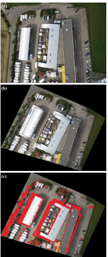
The occlusion detection was carried out for 17 images separately and the results were merged to cover all the interest area. Figure 7 shows the original image (Figure 7.(a)), the double mapping effects after the orthorectification process (Figure 7.(b)), and the occlusion detection regions (Figure 7.(c)).
Figure 7. (a) The original image. (b) The double mapping effect. (c) The occlusion detection.
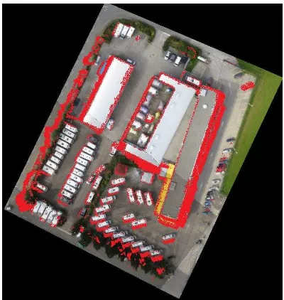
In Figure 7 the occlusion determined automatically by the proposed approach (HGM) was shown. After applying the same procedure for all images and performing a visual analysis for the whole area, the mosaic in Figure 8 was created. Since all input images have gone through the occlusion detection procedure, the results were merged for a visual analysis of the whole test area (Figure 8).
Figure 8. Occlusion detection for the area of interest based on the proposed approach - HGM.
The true orthophoto generation needs an important step of filling the missed radiometric information (red portions in Figure 8). To find the best image to collect the missing radiometric information, one possibility is to use cost functions, as mentioned in Section 2. This procedure is not the focus of this paper, so the true orthophoto was created only by searching the missing radiometric information in all adjacent images without radiometric compensation. Figures 9 and 10 present the obtained true orthophoto.
Figure 9. The true orthophoto created for the area of interest.
Figure 10. (a) The occlusion detection. (b) The true orthophoto.
The main idea of the true orthophoto generation is to consider the aboveground objects in the orthorectification process. This characteristic may be observed in the result where, for example, the buildings are represented in their orthogonal projection.
The result still contains some missing radiometric information, as shown in Figures 9 and Figure 10.(b) – black pixels. This occurs mainly due to two reasons:
(a) The generated DSM by the dense image matching contains too many noise points. This artifact occurs due to moving objects (some cars in the image), along walls, and roof edges. Since the HGM uses the height variation to identify the occlusion areas, several false visibilities occur due to such a noise in the DSM.
(b) Due to the strong attitude change in a UAV flight and consequently great number of occlusions, some remaining occlusion portions may be present if the number of images is not enough to cover completely the region of interest. Therefore, the use of more images would decrease the remaining occlusions. It is important to highlight that even if a great number of adjacent images exists, occlusions in the results may still appear in case of false visibility detection, as mentioned in (a).
4. CONCLUSIONS AND CONSIDERATIONS FOR FUTURE WORK
Orthophotos are widely used in several applications that need an image or knowledge of the space to take decisions. In projects carried out in urban areas, or at least in regions with buildings, the viewpoint-dependent and relief displacements must be corrected. This process requires the occlusion detection procedure. This paper presents a new method for the occlusion detection based on height gradients. Nowadays, due to different reasons, including legal aspects, it is still not common to use UAV imagery in urban areas, but as soon as such restrictions are relaxed, the occlusion detection will be a necessary step, mainly for UAV dataset that has a low-altitude when compared to a conventional airborne mission.
One essential aspect in this method is the importance of having good EOP. In this case, the experiments were carried out with no GCP but with one UAV system that uses a GNSS/IMU and RTK technique aim for providing good platform/camera position and attitude information during the image acquisition.
The presented results show the potential of the method in terms of occlusion detection in UAV images. Some improvements are still essential, such as a smoothing process to avoid false visibilities and the implementation of a cost function to search for best adjacent image to be used for
providing missing radiometric information. Additionally, it is also necessary to have a post-processing step to compensate for radiometric differences.
ACKNOWLEDGEMENTS
The authors thank the FAPESP (Fundação de Amparo à
Pesquisa do Estado de São Paulo - Brazil) for the doctorate
scholarship given to the first author (grant nº 2013/21647-2). Additionally, we thank the Department of Cartography (São Paulo State University - Brazil) and the Department of Civil Engineering (Purdue University – USA) for providing valuable facilities/resources.
REFERENCES
Amhar, F.; Jansa, J.; Ries, C., 1998. The generation of true orthophotos using a 3D building model in conjunction with a conventional DTM. In: International Archives of Photogrammetry and Remote Sensing, v. 32, pp.16-22.
Barrazzetti, L.; Brumana, R.; Oreni, D.; Previtali, M.; Roncoroni, F., 2014. True-orthophoto generation from UAV images: implementation of a combined photogrammetric and computer vision approach. In: ISPRS Technical Commission V Symposium. v. II-5, Riva del Garda, Italy, pp. 57-63.
Gruen, A., 2012. Development and status of image matching in photogrammetry. The Photogrammetric Records. v. 27(137), pp. 36-57.
Habib, A. F.; Kim, E.; Kim, C., 2007. New Methodologies for True Orthophoto Generation. Photogrammetric Engineering & Remote Sensing. v.73, nº 1, pp. 25-36.
Hirschmüller, H., 2008. Stereo processing by semiglobal matching and mutual information. IEEE Transactions On Pattern Analysis and Machine Intelligence. v. 30, nº 2, pp. 328-341.
Lari, Z.; Habib, A. F., 2015. A new approach for segmentation-based texturing of laser scanning data. In: The International Archives of the Photogrammetry, Remote Sensing and Spatial Information Sciences. v. XL-5/W4, pp. 115-121.
Mikhail, E. M.; Bethel, J. S.; McGlone, J. C. Introduction to Modern Photogrammetry. New York: John Wiley & Sons, Inc. 2001. 479 p.
Oliveira, H. C.; Galo, M., 2013. Occlusion detection by height gradient for true orthophoto generation, using LiDAR data. In: The International Archives of the Photogrammetry, Remote Sensing and Spatial Information Sciences. v. XL-1/W1, pp. 275-280.
Paparoditis, N.; Thom, C.; Jibrini, H., 2000. Surface reconstruction in urban areas from multiple views of aerial digital frame cameras. In: International Archives of Photogrammetry and Remote Sensing. v. XXXIII, Supplement B3, Amsterdam, pp. 43-50.
Rieke, M.; Foerster, T.; Geipel, J.; Prinz, T., 2011. High-precision positioning and real-time data processing of
UAV-systems. International Achieves of Photogrammetry and Remote Sensing. v. XXXVII-1/C22, p. 119-123, 2011.
Schickler, W.; Thorpe, A., 1998. Operational procedure for automatic true orthophoto generation. In: International Achieves of Photogrammetry and Remote Sensing. v. 32, Part 4. pp. 527 – 532.
Sensefly, 2015. Drones: example datasets from Postflight Terra 3D. https://www.sensefly.com/example-datasets-from-postflight-terra-3d.html (25 May 2015).
Stempfhuber, W.; Buchholz, M., 2011. A precise, low-cost RTK GNSS system for UAV applications. In: International Achieves of Photogrammetry and Remote Sensing. v. XXXVII-1/C22, pp. 289-293.
Wang, X.; Xie, J., 2012. A method for true orthophoto generation based on projection and iteration strategy. ISPRS Annals of the Photogrammetry, Remote Sensing and Spatial Information Sciences, v. I-4, Melbourne, Australia, pp. 311-314.
Wolf, P. R.; Dewitt, B. A., 2000. Elements of Photogrammetry – with applications in GIS. 3rd edition. New York: McGraw-Hill, 608 p.