THE “ART OF WAR FRIEZE” IN URBINO:
A BLEND OF VIRTUAL RECONSTRUCTION AND SCIENTIFIC ACCURACY
Laura Baratina, Monica Giuliano a, Giovanni Checcucci b
aDiSBEF - University of Urbino, Campus Scientifico – „ E. Mattei“, 60129 Urbino, Italy, [email protected],
b ABC General Engineering s.r.l., 50132 Florence, Italy, [email protected]
Commission V, WG V/4
KEY WORDS: 3D MODEL, CONSERVATION, HISTORICAL MONUMENTS, DIGITAL MAP, PHOTOGRAMMETRY, LASER SCANNER
ABSTRACT:
The Art of War Frieze was commissioned by Federico da Montefeltro, Duke of Urbino, to decorate the back of the «wing façade» of the Ducal palace. The Frieze decorated the façade from the time it was realised towards the end of the XVth century until 1756. The Frieze consists of a very particular series of seventy-two limestone bas-reliefs, whose iconographic repertoire represents numerous war and building machines as well as military and political symbols. After it broke away from the outdoor façade it was stored in different rooms in the Palace but despite the many documentary records available, the question of the original sequence of the bas-reliefs has never been resolved.
The primary scope of this paper is to create a “virtual” reconstruction of the original sequence of the bas-reliefs, starting from historical and iconographic records, an analysis of the back and the individual panels using a laser scanner and fully automatic open source photo modelling technologies like the Arc3d, and photogrammetric systems like Image Master together with analyses of the state of conservation, type of degradation correlated to atmospheric parameters (sunlight, temperature, rain).
Tests will then be carried out with different systems in order to confirm the accuracy of the model if it is decided to reproduce the individual panels using the rapid prototyping technique associated to a study of the execution techniques.
1. HISTORICAL INFORMATION ON THE FRIEZE
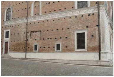
The Art of War Frieze was commissioned by Federico da Montefeltro, Duke of Urbino, to decorate the back of the «wing façade » of the Ducal palace in order to characterise his home, and bear witness to his glorious life and position in the history of the Renaissance.
Figure 1. “Wing façade” of the Ducal Palace
The Frieze decorated the façade, complete with a bench and delicately finished stringcourse cornice, from the time it was realised towards the end of the XVth century until 1756, when it was removed by the architect Giovan Francesco Buonamici against the orders Cardinal Giovan Francesco Stoppani, who was a papal delegate in Urbino, to create the “Museum of Ancient Headstones” in the Upper Loggias of the Palace as testimony of the past. Removal of the frieze proved to be difficult and records show that a number of elements were damaged (for example panel 60 no longer exists and may be reconstructed only thanks to engravings by Gaetano Piccini
published in the text by B. Baldi, Memorie concernenti la città dating to 1724), but the new layout does not take into account its original position, attributing a new order according to criteria that are today still subject of much debate. The only very positive aspect was that the Frieze was removed from the action of weather elements that were gradually eroding the same.
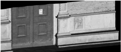
Figure 2. Detail of the back towards the Church of San Domenico
The Frieze consists of a very particular series of seventy-two limestone bas-reliefs whose iconographic repertoire represents numerous war and building machines, as well as military and political symbols.
Originally the panels were placed in frames and placed next to each other to form a long decorative belt that extended from the side door of the Palace, facing the Church of San Domenico to the façade of the Castle. No records refer to the order in which the reliefs were positioned on the facade.
Museum were moved; the archaeological collection of works were transferred to the ground floor while the panels were stored in some of the less important rooms of the Palace (1944). The bas-reliefs which were still in good condition were walled into the rooms facing the Pasquino courtyard and grouped according to the iconographic objects represented while all the others were moved to the storerooms of the Palace.
In about 1980 the panels were placed in the Chancellery, after being restored under the supervision of Arduino Spegne. Today the bas-reliefs are still positioned side by side in the number order provided by Bianchini in the text Spiegazione delle sculture contenute nelle LXXII tavole di marmo e bassorilievi collocati nel basamento esteriore del palazzo di Urbino, published in 1724. The first forty-eight panels are in the first hall, while the other thirteen panels are in a neighbouring room; they stand on white Plexiglas bases and are fixed to the walls with metal brackets on the back.
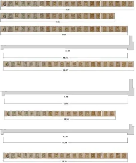
Figure 3. Current layout of the Frieze
We owe the earliest iconographic interpretation of the Frieze to Bianchini, while another important source is the book by G. Bernini Pezzini called “Il fregio dell’arte della guerra nel Palazzo Ducale di Urbino” dating to 1985 that gives an interpretation of the symbols and explains the operating mechanisms of the machines portrayed on each panel. The engraved representations may be grouped in four main categories: engineering works, panoplies, nautical symbols and military art. The various objects refer to different essays: from the Codes by Francesco di Giorgio Martini to drawings by Roberto Valturio dating to the middle of the XV century, which are useful for the current representation of a number of badly damaged panels.
Figure 4. Panel 72 – Engineering Works portraying a crane, together with a reproduction from the Code by F.di G. Martini
2. THE EXECUTION TECHNIQUES
The analysis of the state of conservation, and above all the study of the executing techniques, is one of the additional factors taken into account in recomposing the frieze. The Frieze consists of seventy-two bas-reliefs probably dating to different periods. It should be noted in fact that although the height of the panels is the same (on average 84 cm.), the widths vary. Moreover each bas-relief does not consist of a single block of stone, but is often divided into several parts.
Some panels consist of a single block with a width of about 95 cm, while others are 3-piece blocks consisting of a central block with the representation and two side blocks of about 64.5 cm;
the very few single-block panels (2, 4, 9, 14, 25, 27, 33, 34, 37, 43, 47, 50, 65, 70, 72) all have very different widths.
Figure 5. Panel 36 – Panoply: 3-piece block, the arrows indicate the right edge still visible in a photo dating to the 50’s
This would make it fair to suppose that the blocks were not squared very accurately, admitting that all the remaining panels were produced with a variable number of pieces. Observing the blocks of each relief more carefully, it was noted that in most cases the side frames do not seem to match the central block; this anomaly is also confirmed by the different colours of the two pieces. Taking into account the vicissitudes experienced by Frieze, it must be supposed that the panels were inevitably assembled inaccurately. Records regarding the relocations and maintenance carried out in the 80’s confirm that various problems were encountered in assembling the parts, given the many missing parts. The above considerations and an analysis of archive photographs, in particular those referring to the relocation of the reliefs in the Stoppani Buonamici Museum, make it fair to suppose that some blocks originally had two or more bas-reliefs which were cut off during the continuous transfers from the Museum to the halls of the Palace. Moreover, observing the few existing whole panels and the surviving pilaster strips that divided one panel from another, it might be possible to conclude that each or several panels consisted of a single block and that each panel was divided from the others by strips having uniform dimensions.
the workmanship, the tools used and working method may be useful to evaluate possible reproductions.
Figure 6. Panel 57: Assumed working phases, from the block to the object portrayed
3. THE SURVEYS, INITIAL RE-COMPOSITION ASSUMPTIONS
The question of the original sequence of the bas-reliefs on the façade has not yet completely been resolved; Bianchini’s text is the only important account that provides constructive information on this matter, even if it does not clearly indicate the precise layout of the panels on each section of the back. The only element that provides a number of interesting facts regarding the number of panels positioned in each segment, is an engraving (illustrated in Bianchini’s text) showing the eighteenth century urban system of the town, including the Ducal Palace, the two squares Rinascimento and Duca Federico and the Cathedral. The picture gives an approximate subdivision of the back into seventy-two panels. The reproduction of the Frieze is rather small and therefore cannot be considered as fully objective; it does however provide a number of useful elements to trace the precise layout.
Pezzini’s text gives a diagram of the panel layout showing the subdivision of the back as illustrated in the engraving: the number of panels in each segment of the back is the following (starting from the front door of the church of San Domenico): 18, 6, 6, 6, 6, 4, 13 and 13.
The text also gives another diagram of the layout of the bas-reliefs on the façade, taken from drawings by Piccini: 21, 5, 1, 5, 6, 7, 13 and 12.
Based on these considerations, the initial tests were carried out by plane photogrammetric analysis, using the software Archis 2d which was used to rectify the images of both the panels and wings of the Palace façade.
In order to carry out the dimensional controls and a “virtual” reallocation of the bas-reliefs in their original position, laser scans were performed with the Leica HDS6000 phase-shift scanner, with scans that gave as much detail as possible in the area delimiting the bench.
Figure 7. Laser scanner reading of the benches on the facade
As a first step, the panels were placed side by side in the number order according to Bianchini, as they are today, following the two layouts of Bianchini and Piccini respectively. It was noted that when placed alongside the bas-reliefs, some of the rectangular strips did not match.
The second step consisted of analysing the executing techniques and arrangement of the bas-reliefs with respect to the frames and rectangular strips.
After examining the surviving pilaster strips, both as individual elements and as blocks making up the bas-reliefs, taking into account the above historical considerations and comparisons with the road benches of other Renaissance buildings, above all in Florence and Rome, the conclusion was reached that each bas-relief was separated from the others by pilaster strips having uniform dimensions with assumed average width of approximately 22 cm.
a)
b)
Figure 8. Layout of the panels on the Eastern façade of the Palace according to the diagrams of Piccini (no. 21) and Bianchini (no.18). According to the measurements taken, please note a) a non-matching strip b) exclusion of the strip
Figure 9. Assumed reconstruction of the average dimensions of
each pilaster strip
Again following the two diagrams available, the panels were then placed side by side and compared with the real measurements of the benches of the Palace facades, confirming in both cases that they do not match.
Introducing a number of considerations in this first analysis regarding the different types of degradation due to three centuries of exposure to the elements (rain erosion, solar irradiation, humidity etc.) of the facades, a different layout of the bas-reliefs was assumed, that would in part entirely alter the two sources but which would be more coherent from a metric point of view.
Figure 10. Reconstruction of the panel order on the Eastern façade with reallocation of the pilaster strips according to the diagrams of Piccini (21) and Bianchini (18) and according to the new assumptions (20), perspective and plan views. Note how the new assumptions give a perfect metric match.
4. THE PANELS: A COMPARISON OF RECONSTRUCTION TECHNIQUES
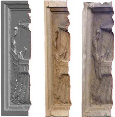
Assuming that the panels were to be reconstructed, tests were carried out using three different systems: laser scanner technology, Image Master Pro software and the web service Arc3d; in order to verify the accuracy of the models both in terms of a 3D reconstruction and possible reproduction of the same using the rapid prototyping technique.
The panel selected for these tests was panel 19 – Quinquereme given its good state of conservation and clearly legible details. The first technology used is based on a scanning system that produces highly detailed scans of medium and small sized objects. The system may be integrated with an arm having 7 degrees of freedom thus making it possible to easily perform contact or non-contact measurements of the object in question. This type of scan is carried out at a scanning speed of more than 19.000 points per second, thus making it possible to rapidly scan very complex shapes with a very high level of accuracy. Use of the Laser Line Probe CAM2 methodology permitted obtaining highly detailed scans.
Figure 11. Panel 19 – Model scanned with the Laser Line Probe CAM2 system and reconstruction with rapid prototyping
systems
The second test was carried out using the software Image Master Pro which processes measurements obtained from stereo images, generating orthophotos and 3D models. The captured were taken with a Panasonic DMC-ZX1 digital camera calibrated with a focal length of 45 mm. During data processing the limits of the system were observed; since collimation is an autocorrelation process, during definition of the polylines or breaklines on the model, this may in fact cause numerous problems due to the difficulty of recognising homologous points. Autocorrelation is in fact always a procedure that entails a large margin of error because it is tied to contingent factors like morphology, and above all the nature of surfaces. During the orientation phase, the software operates according to a strict photogrammetric principle, giving excellent results with a very low error margin, but in the model creation phase it requires various data, the most important of which is the definition of the polylines when there are evident height variations or elements of strong discontinuity, which create significant inconsistencies in results between the orientation and model creation phases.
Figure 12. Panel 19 – Model created with Image Master Pro
automation which makes it possible to interact only in part with the model.
Figure 13. Panel 19 – Model created with Arc3d
Comparing the initial results of the three models in terms of quality, quite obviously the first is the most reliable and detailed, while contrary to expectations, the Arc3d seems to give more satisfactory results with respect to Image Master Pro that gives very accentuated smoothing and less detailed geometries.
The next tests will be carried out on other panels with different levels of degradation in order to verify the possibility of integrating geometric data, historical drawings and executing techniques in order to obtain a dimensionally and morphologically accurate reproduction.
Figura 13. Panel 19: Sections obtained respectively from the laser model, Arc3d and Image Master Pro
References
1590 – B. Baldi, Descrizione del Palazzo ducale di Urbino (1587), Venezia.
1724 – F. Bianchini, Spiegazione delle sculture contenute nelle LXXII tavole di marmo e bassorilievi collocati nel basamento esteriore del palazzo di Urbino, in B. Baldi, Memorie concernenti la città di Urbino, Roma.
1968 – F.P. Fiore, Città e macchine del ‘400 nei disegni di Francesco di Giorgio Martini, Firenze.
1970 – P. Rotondi, Francesco di Giorgio nel Palazzo ducale di Urbino, Novilara.
1985 – G. Bernini Pezzini, Il fregio dell’arte della guerra nel palazzo ducale di Urbino, Roma.
1989 – E. Mandelli, Palazzi del Rinascimento: dal rilievo al confronto, Firenze.
2006 – L. Molari, P. G. Molari, Il trionfo dell’ingegneria nel fregio del palazzo ducale d’Urbino, Pisa.
2006 - M. Vergauwen and L. Van Gool, Web-based 3D Reconstruction Service, in Machine Vision Applications (MVA), 17, pp. 411-426.
2010 – M. Filippucci, Nuvole di pixel. La fotomodellazione con software liberi per il rilievo d’architettura, in Disegnare con, n 50, ISSN 1828-5961.
2011 - L. De Luca, La fotomodellazione architettonica, Roma. 2012 – L. Baratin, Survey and representation of architectural and archaeological assets: a summary of methodologies and applications. L. Baratin (Ed) Instruments and Methodologies for Cultural Heritage Conservation and Valorisation. Editor Gabbiano 2012, Ancona, pp. 85-90.
Acknowledgements
Our thanks go to the Marche BSAE Superintendency, Ms M. L. Amadori and C. D’Apice for the section on the analysis on the state of conservation of the Frieze; Aurea Servizi s.a.s. of Mondaino (RN) for the laser scans of two panels and Leica Geosystem s.r.l. for the equipment used for the surveys on the facades of the Ducale Palace.