FUSING PASSIVE AND ACTIVE SENSED IMAGES TO GAIN INFRARED-TEXTURED
3D MODELS
Martin Weinmanna, Ludwig Hoegnerb, Jens Leitloffa, Uwe Stillab, Stefan Hinzaand Boris Jutzia
a
Institute of Photogrammetry and Remote Sensing, Karlsruhe Institute of Technology (KIT) {martin.weinmann, jens.leitloff, stefan.hinz, boris.jutzi}@kit.edu
b
Institute of Photogrammetry and Cartography, Technische Universit¨at M¨unchen (TUM) ludwig.hoegner@bv.tum.de, stilla@tum.de
Commission I, WG I/2
KEY WORDS:Point Cloud, Imagery, Sequences, Multisensor, LIDAR, Thermal, Infrared, Close Range
ABSTRACT:
Obtaining a 3D description of man-made and natural environments is a basic task in Computer Vision, Photogrammetry and Remote Sensing. New active sensors provide the possibility of capturing range information by images with a single measurement. With this new technique, image-based active ranging is possible which allows for capturing dynamic scenes, e.g. with moving pedestrians or moving vehicles. The currently available range imaging devices usually operate within the close-infrared domain to capture range and furthermore active and passive intensity images. Depending on the application, a 3D description with additional spectral information such as thermal-infrared data can be helpful and offers new opportunities for the detection and interpretation of human subjects and interactions. Therefore, thermal-infrared data combined with range information is promising. In this paper, an approach for mapping thermal-infrared data on range data is proposed. First, a camera calibration is carried out for the range imaging system (PMD[vision] CamCube 2.0) and the thermal-infrared system (InfraTec VarioCAM hr). Subsequently, a registration of close-infrared and thermal infrared intensity images derived from different sensor devices is performed. In this context, wavelength independent properties are selected in order to derive point correspondences between the different spectral domains. Finally, the thermal infrared images are enhanced with information derived from data acquired with the range imaging device and the enhanced IR texture is projected onto the respective 3D point cloud data for gaining appropriate infrared-textured 3D models. The feasibility of the proposed methodology is demonstrated for an experimental setup which is well-suited for investigating these proposed possibilities. Hence, the presented work is a first step towards the development of methods for combined thermal-infrared and range representation.
1 INTRODUCTION
Deriving an appropriate 3D description of man-made and natural environments is of great interest in Computer Vision, Photogram-metry and Remote Sensing. Most of the current approaches are based on the use of image and/or range data. Simultaneously capturing intensity information of high quality as well as range information by images with a single measurement, new active sensors seem to be well-suited for solving this task even in de-manding environments. However, the acquired intensity typically represents information of the visual domain and hence, only ra-diometric and geometric surface properties of observed objects are captured which might not always be sufficient. In contrast to this, infrared (IR) cameras sense thermal radiation in the infrared spectrum which is emitted by objects in the scene and not visible in visual images. Thus, the captured images offer a different look on objects and the extraction of additional information like tem-perature and material of observed objects. Especially in build-ing observation (Iwaszczuk et al., 2011; Hoegner et al., 2007a), the extraction of textures on fac¸ades of buildings allows a recon-struction of the surface temperature and a look into the interior behavior of a wall. Different materials, heating pipes and leak-ages can easily be identified and added as semantic or geometric information to the building model. A major challenge in the anal-ysis of infrared images is the low geometric resolution compared to classical optical camera systems and the behavior of infrared. Objects visible in the visual domain may be invisible in the in-frared domain if they have the same temperature as the respec-tive background. On the other hand, in infrared images, objects may be visible below the surface of an object and thus remain invisible in the visual domain. In general, lines and edges do not
show strong edges but appear blurred. These effects cause mis-matches between infrared and visible domain images and reduce the accuracy of object detection and extraction in infrared images. Especially in close-range applications such as indoor building in-spections or industrial processes, additional sensors are necessary to improve the accuracy of infrared images.
Hence, a fusion of infrared and visual domain images can en-hance features in both kinds of images and even reveal new fea-tures that might not be present in either IR or visual images (Chen and Leung, 2009; Bai et al., 2011). Furthermore, the fusion of these different types of image data has been applied for increasing the spatial detail and spectral accuracy of Landsat ETM+ thermal data by fusion with an IKONOS image representing vegetation (Nichol and Wong, 2005), for contrast enhancement in environ-ments of poor visibility or inadequate illumination (Liu and La-gani`ere, 2007), for target detection (Yao and Sekmen, 2008) and for concealed weapon detection (Xue et al., 2002). The regis-tration of such image data representing information in different spectral bands has for instance been investigated using a segment-based approach (Coiras et al., 2000) or an approach involving normalized mutual information (Park et al., 2008).
repre-sentation of a different spectral domain allows for transferring the complementary information onto the 3D point cloud. Further exploiting the properties of the co-registered images even yields improved 2D texture information and finally, 3D models with an enhanced texture. The contributions of this paper are
• the presentation of a sensor platform which allows for fusing passive and active sensed images within outdoor and indoor environments,
• a novel methodology for a fully automatic registration of images with different radiometric properties and a subse-quent sharpening of image information, which is tested for an example involving image information of a thermal in-frared camera as well as intensity and range information of a range imaging device, and
• the generation of enhanced infrared-textured 3D models.
Considering flat building fac¸ades and walls, the proposed method-ology is focused on almost planar scenes. The extension to non-planar scenes is beyond the scope of this paper.
The remainder of this paper is organized as follows. In Section 2, the proposed methodology for gaining infrared-textured 3D mod-els is described. The configuration of the used sensors and their specifications are described in Section 3. Subsequently, experi-mental results of the presented approach are shown in Section 4. The derived results are discussed in Section 5. Finally, in Section 6, the content of the entire paper is concluded and suggestions for future work are outlined.
2 METHODOLOGY
The proposed methodology involves data captured with two dif-ferent devices, where one device provides texture information of lower quality such as infrared information, and the other device captures intensity information with a high quality as well as range information. After data acquisition, a preprocessing has to be car-ried out which consists of the normalization of intensity data, a camera calibration for the used devices and the respective correc-tions of the measured 3D point cloud (Section 2.1). Subsequently determining point correspondences between the image represen-tations via manual selection or automatic estimation (Section 2.2) yields the information required for a robust image registration in-volving the RANSAC algorithm (Section 2.3). Once an accurate image registration has been achieved, an image sharpening can be realized which exploits the high quality of an intensity image for enhancing infrared texture information of lower quality (Section 2.4). Finally, the projection of the enhanced IR texture onto the corrected 3D point cloud is carried out and unreliable 3D points are removed (Section 2.5).
2.1 Preprocessing
In a first step, the captured data has to be adapted with respect to radiometric and geometric constraints. During the measurements, the thermal information already is assigned a color value accord-ing to a certain colorbar. The intensity information captured with the range imaging device is adapted by applying a histogram nor-malization which adapts the intensity informationIto the interval [0,255](Weinmann and Jutzi, 2012). For the example of an in-door scene, the recorded information is shown in Figure 1 and Figure 2.
In the depicted figures, it becomes clearly visible that the image information is distorted and for this reason, a camera calibration has to be carried out for the used devices which yields a cor-rected grid of image coordinates. The geometric calibration of
Figure 1: Visualization of the data captured with an InfraTec Var-ioCAM hr.
Figure 2: Visualization of the data captured with a PMD[vision] CamCube 2.0: Normalized active intensity, normalized passive intensity and range data (from left to right). The range increases from red pixels via yellow and green pixels to blue pixels.
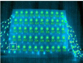
the infrared camera is based on well-known principles but has to be adapted. Calibration tables such as chessboard patterns are not visible in infrared images. Hence, a pattern visible in the thermal domain is necessary. In our case, a regular grid of small filament lamps was attached at the backside of a wood pattern with holes for every light source. The resulting grid of tempera-ture light sources was measured by a calibrated photogrammetric camera. This calibration grid was recorded by the infrared cam-era from nine different positions with a fixed focal length. The program Leica Photogrammetry Suite (LPS) was used to perform a bundle adjustment of the infrared images using the known rel-ative coordinates of the light points from the photogrammetric measurement as ground control points and tie points between the different images (Figure 3). Due to the redundancy in the visi-bility of the light points, the exterior and interior orientation of the infrared images can be estimated. The interior orientation was estimated with five parameters for focal lengthf, principal point(x0, y0)and radial distortion(A1, A2). The geometric cal-ibration of the range imaging device is carried out according to standard methods and the respective 3D information in the local coordinate system can then be derived by applying the correction method proposed in (Weinmann and Jutzi, 2012).
Figure 3: One infrared image of the calibration grid with marked tie points.
2.2 Detection of Point Correspondences
point selection, an implicit description of the local characteristics which allows for detecting corresponding points in different im-ages and the final matching which yields a set of reliable point correspondences without outlier correspondences.
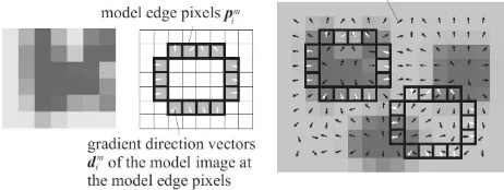
Besides the manual detection of point correspondences, an auto-matic algorithm has also been inserted into the whole processing scheme which uses normalized intensity information of the range imaging device and the thermal information of the infrared cam-era transformed to gray values. Whereas a fully automatic detec-tion of point correspondences via standard techniques such as the SIFT algorithm (Lowe, 2004) typically fails due to the different characteristics of the compared images, the shape-based match-ing algorithm proposed in (Steger, 2001) and (Ulrich, 2003) is still able to derive feature correspondences of which a certain per-centage provides a high reliability. The principle of this algorithm is illustrated in Figure 4. First, a model image has to be gener-ated which is achieved by selecting quadratic areas of100×100 pixels around points of a discrete grid with a grid spacing of10 pixels in the first image. Subsequently, a gradient filter is ap-plied to the model image and the associated gradient directions are determined. The model image is matched to the gradients of the search image by comparing the respective gradient directions. In particular, a similarity measure is calculated which represents the average vector product of the gradient directions of the trans-formed model and the search image. This similarity measure is robust in case of noise and illumination changes, but not in case of changes in rotation and scale. Hence, the search is extended to a predefined range of rotations and scales. If the derived similar-ity measure is above a certain threshold, a point correspondence is detected. For this correspondence, the coordinates of the cen-ter, the rotation angle and the similarity measure itself are stored. For the experiments, the HALCON 10 implementation (MVTec Software) of this algorithm is used.
Figure 4: Principle of shape-based matching: Model image, model edges and search image according to (Ulrich, 2003).
2.3 Image Registration
Once point correspondences have been detected, the next step consists of calculating the transformation between the respective images. For this, different types of transformations can be cal-culated such as a homography for planar scenes or a fundamen-tal matrix for non-planar scenes. Considering the application of gaining infrared-textured models of building fac¸ades in outdoor scenes or infrared-textured models of walls in indoor environ-ments, an almost planar scene is given for the relevant image re-gions. Hence, the model of a homography can be used for es-timating the transformation between the images and deriving a superposition of them.
A homography is a perspective transformation model for planes and it represents a linear transformation in the projective space P2, where 2D pointsxof a planeπare mapped onto 2D points x′of a planeπ′ according tox′ =H·x. As the 2D pointsx
andx′are considered in homogeneous coordinates, the homog-raphy matrixHis a(3×3)matrix and for applications involving camera-like devices, the planesπandπ′represent the respective
image planes. The estimation of a homography is typically car-ried out via the normalized Direct Linear Transformation (Hartley and Zisserman, 2008) and, for a robust estimation in case of ex-isting outlier correspondences, the RANSAC algorithm (Fischler and Bolles, 1981) provides a good possibility as it completely eliminates the influence of such outlier correspondences.
2.4 Image Sharpening
For the almost planar scene content, the co-registered IR texture can then be sharpened by using the intensity information cap-tured with the range imaging device. The passive intensity image provides texture information with a high frequency whereas the infrared image only contains texture information with a signifi-cantly lower frequency. For sharpening the transformed infrared image, the image locations for a possible image enhancement can be derived around edges in the passive intensity image. Hence, the edge imageEIpis derived by convolving the passive intensity imageIpwith a Laplacian filterLof the form
L=
Subsequently, the image sharpening is carried out by adding the weighted edge image to each channel of the transformed infrared image in the RGB color space which can formally be described as
IIR,sharpened=IIR+β·EIp (3)
whereβ∈Ris a constant parameter.
2.5 Projection to 3D Space
Finally, the enhanced IR texture has to be projected onto the re-spective 3D objects. As the 3D measurements obtained with the range imaging device are corrupted with noise, a certain percent-age of unreliable measurements is likely to occur and hence has to be removed for receiving accurate 3D models. In order to de-tect such unreliable 3D measurements, the standard deviationσ
of the range measurements within a(3×3)neighborhood of each pixel is calculated (Weinmann and Jutzi, 2011). If the standard deviationσof the respective range values is larger than a pre-defined thresholdtσ, the range information of the center pixel is not reliable, otherwise the range information of the center pixel is assumed to be reliable. The unreliable 3D measurements are discarded and the sharpened IR texture is then projected onto the remaining points of the captured and corrected 3D point cloud.
3 CONFIGURATION
hence, it can be used for sharpening the thermal information if the different types of data are mapped onto the same image grid.
As the devices utilized for deriving infrared-textured 3D models should be suited for capturing indoor scenes as well as outdoor scenes, the use of scanning devices based on structured light is impractical. Furthermore, the sensor platform should also be ca-pable for dynamic observations where terrestrial laser scanners fail as they typically perform a time-dependent spatial scanning of the scene. Hence, the combination of an InfraTec VarioCAM hr and a PMD[vision] Camcube 2.0 is proposed in this paper. These devices have been mounted on a sensor platform as shown in Figure 5. Thus, the devices are coupled and a fixed relative orientation between them is preserved.
Figure 5: Sensor configuration: PMD[vision] CamCube 2.0 (left) and InfraTec VarioCAM hr (right).
3.1 PMD[vision] CamCube 2.0
A PMD[vision] CamCube 2.0 simultaneously captures geometric information as well as radiometric information and thus various types of data by images with a single shot. In contrast to the clas-sical stereo observation techniques with passive sensors, where a data acquisition from at least two different viewpoints and a subsequent co-registration of the captured data has to be car-ried out, the monostatic sensor configuration of the PMD[vision] CamCube 2.0 preserves information on a discrete 2D grid with-out the need of a co-registration of the captured data. For each point on this discrete grid, three features are measured, namely the respective range, the active intensity and the passive intensity. The active intensity depends on the illumination emitted by the sensor, whereas the passive intensity depends on the background illumination arising from the sun or other external light sources. Using the grid information, the different types of data can be rep-resented as images. These images have a size of204×204pixels which corresponds to a field of view of40◦×40◦and hence, the device provides measurements with an angular resolution of ap-proximately0.2◦. As a single frame consisting of a range image
IR, an active intensity imageIaand a passive intensity imageIp can be updated with high frame rates of more than25releases per second, it is also suited for capturing dynamic scenes.
However, the non-ambiguity range which is also called unique range is less than10m and depends on the tunable modulation frequency. In order to overcome this range measurement restric-tion, image- or hardwabased unwrapping procedures have re-cently been introduced (Jutzi, 2009; Jutzi, 2012).
3.2 InfraTec VarioCAM hr
The used infrared camera is a bolometer-based VarioCAM hr from InfraTec. Its sensor records in the wavelength interval from 7.5−14µm with a radiometric resolution of0.05K. The im-age representation of the captured thermal information has a size of384×288pixels and, considering an angular resolution of
approximately0.16◦, this corresponds to a field of view of ap-proximately61◦×46◦. As the frame rate is25fps, this device can also be applied for observing dynamic scenes.
4 EXPERIMENTAL RESULTS
For testing the proposed methodology, an almost planar indoor scene is considered, as the main focus is set on applications where flat building fac¸ades or walls are present. The recorded texture information which is used for deriving the transformation be-tween the respective images consists of the passive intensity age recorded with the PMD[vision] CamCube 2.0 and the IR im-age acquired with the InfraTec VarioCAM hr which are shown in Figure 6. The undistorted images after a correction involving the parameters determined in the camera calibration procedure are illustrated in Figure 7.
Figure 6: Passive intensity image and IR image for an almost planar scene.
Figure 7: Passive intensity image and IR image after undistortion and after removal of irrelevant information.
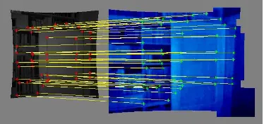
Subsequently, the manual selection of44point correspondences is carried out which are shown in Figure 8, and all of them are considered as inlier correspondences. In contrast to this, the au-tomatic shape-based matching algorithm detects a total number of 484point correspondences, where a large number of outlier cor-respondences is contained. Due to the RANSAC-based scheme, these outlier correspondences are detected and discarded. This yields a set of151reliable point correspondences which are de-picted in Figure 9, i.e. only31.20% of all point correspondences are involved in estimating the respective homography. The map-ping of the IR texture onto the respective intensity information is illustrated in Figure 10 for both the manual and the automatic determination of point correspondences. The results are almost identical except on the left border of the overlapping area where the manual selection yields a more accurate transformation.
Once an accurate image registration has been achieved, the image sharpening can be carried out. The results before and after image sharpening when using a constant factor ofβ= 1.0are shown in Figure 11. This clearly indicates the feasibility of the proposed approach.
Figure 8: Manually selected point correspondences between the masked images.
Figure 9: Automatically selected point correspondences between the masked images.
Figure 10: Passive intensity image and transformed IR image for manual determination of point correspondences (left) and auto-matic determination (right).
Figure 11: Transformed IR image before sharpening (left) and after sharpening (right).
in order to gain more accurate 3D models. The derived measure
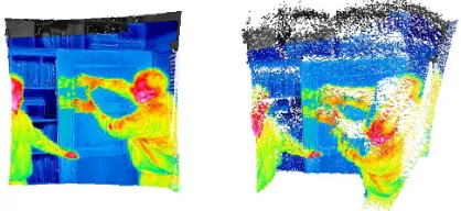
σfor the reliability of 3D points is visualized in Figure 12. It becomes visible that points which arise from objects in the scene provide a smoother surface whereas points along edges tend to be very noisy. For discarding 3D points which do not lie on the surface of any object in the scene, a threshold oftσ = 0.1m is used for the standard deviation of the range measurements within local(3×3)neighborhoods and all points with a valueσ > tσ are removed. In Figure 13 and Figure 14, the effect of this filter step is shown for both a frontal view and a side view onto the infrared-textured 3D point cloud.
5 DISCUSSION
As shown above, the presented methodology is well-suited for mapping image data with different characteristics, where
stan-Figure 12: Visualization of the reliability of the range measuments: Reliable measurements are represented in red and the re-liability decreases via yellow, green and blue to violet.
Figure 13: Frontal view onto the infrared-textured point cloud before and after removing unreliable points.
Figure 14: Side view onto the infrared-textured point cloud be-fore and after removing unreliable points.
dard approaches such as the SIFT algorithm tend to fail when reliable point correspondences are required. In comparison to a manual selection of point correspondences and a subsequent estimation of the respective transformation, the fully automatic approach also yielded a good result, but a slight decrease of the mapping quality became visible at the left border of the over-lapping area. This shows that additional constraints have to be considered in the optimization process in order to obtain an even more accurate transformation.
The accurate image registration is essential for a mapping any kind of texture acquired with a certain device onto 3D point cloud information obtained with a different device. For the example of IR texture with lower quality, it has further been demonstrated that this texture, can significantly be improved by also taking the intensity information into account which nowadays is usu-ally gained with terrestrial laser scanners, time-of-flight cameras or modern devices based on the use of structured light.
by modifying the utilized transformation model. If the scene for instance contains 3D information on different planes, the mea-sured range information can be used for estimating the different planes and subsequently grouping the point correspondences ac-cording to these planes. A subsequent multi-homography fitting can be exploited for a robust region-based registration of the tex-ture information which would especially be applicable in urban environments. For scenes without such regular object surfaces, other transformation models have to be utilized or deformations of image regions have to be introduced. Furthermore, informa-tion derived from the acquired 3D point cloud could be involved for supporting the image registration process.
Figure 15: Frontal view onto a non-planar scene (left) and a view clearly showing the erroneous shifts of IR texture in the point cloud (right).
6 CONCLUSIONS AND FUTURE WORK
In this paper, a novel methodology for fusing passive and active sensed images with different radiometric properties has been pre-sented which allows for mapping different kinds of texture in-formation onto 3D models obtained with a different device. The feasibility of the proposed methodology has clearly been demon-strated for the example of fusing image information of a ther-mal infrared camera as well as intensity and range information of a range imaging device. This data fusion culminates in sharp-ening the edges of the IR images by exploiting the high quality of the intensity information acquired with the range imaging de-vice. The enhanced IR texture has further been projected onto the respective 3D point cloud data which resulted in an enhanced infrared-textured 3D model.
However, the approach is limited on planar scenes and hence, an extension to non-planar scenes has to be carried out in future research. Devices such as a thermal infrared camera offer the ability of providing useful information which might not be ade-quately represented in the visual or range information. As mobile sensor platforms nowadays are equipped with different types of sensors, the presented fusion of different types of data and possi-ble extensions can strongly support tasks for scene analysis such as the detection and interpretation of human subjects and interac-tions. Furthermore, a more detailed evaluation is desirable which encapsulates a measure for the quality of image registration, the quality of image sharpening and also the quality of the derived infrared-textured 3D models. The derived results already demon-strated a high potential for future research on data fusion for static and dynamic scene analysis.
REFERENCES
Bai, X., Zhou, F. and Xue, B., 2011. Fusion of infrared and vi-sual images through region extraction by using multi scale center-surround top-hat transform. Optics Express 19(9), pp. 8444– 8457.
Chen, S. and Leung, H., 2009. An EM-CI based approach to fusion of IR and visual images. 12th International Conference on Information Fusion, pp. 1325–1330.
Coiras, E., Santamar´ıa, J. and Miravet, C., 2000. A segment-based registration technique for visual-IR images. Optical Engi-neering39, pp. 282–289.
Fischler, M. A. and Bolles, R. C., 1981. Random sample con-sensus: A paradigm for model fitting with applications to im-age analysis and automated cartography.Communications of the ACM24(6), pp. 381–395.
Hartley, R. I. and Zisserman, A., 2008. Multiple view geometry in computer vision. University Press, Cambridge.
Hoegner, L., Kumke, H., Meng, L. and Stilla, U., 2007a. Auto-matic extraction of textures from infrared image sequences and database integration for 3D building models. PFG Photogram-metrie, Fernerkundung, Geoinformation6 / 2007, pp. 459–468.
Hoegner, L., Kumke, H., Schwarz, A., Meng, L. and Stilla, U., 2007b. Strategies for texturing building models with low resolu-tion infrared image sequences. 5th International Symposium on Mobile Mapping Technology.
Iwaszczuk, D., Hoegner, L. and Stilla, U., 2011. Detection of windows in IR building textures using masked correlation. In: Stilla, U., Rottensteiner, F., Mayer, H., Jutzi, B., Butenuth, M. (Eds.),Photogrammetric Image Analysis, ISPRS Conference - Proceedings. Lecture Notes in Computer Science, Vol. 6952, Springer, pp. 133–146.
Jutzi, B., 2009. Investigations on ambiguity unwrapping of range images. The International Archives of the Photogrammetry, Re-mote Sensing and Spatial Information Sciences38 (Part 3 / W8), pp. 265–270.
Jutzi, B., 2012. Extending the range measurement capabilities of modulated range imaging devices by time-frequency multiplex-ing.AVN - Allgemeine Vermessungs-Nachrichten2 / 2012.
Liu, Z. and Lagani`ere, R., 2007. Context enhancement through infrared vision: a modified fusion scheme. Signal, Image and Video Processing1(4), pp. 293–301.
Lowe, D. G., 2004. Distinctive image features from scale-invariant keypoints. International Journal of Computer Vision 60(2), pp. 91–110.
Nichol, J. and Wong, M. S., 2005. Modeling urban environmental quality in a tropical city. Landscape and Urban Planning73, pp. 49–58.
Park, C., Bae, K.-H., Choi, S. and Jung, J.-H., 2008. Image fu-sion in infrared image and visual image using normalized mutual information.Proceedings of SPIE, Vol. 6968, pp. 69681Q–1–9.
Steger, C., 2001. Similarity measures for occlusion, clutter, and illumination invariant object recognition. In: Radig, B. and Flor-czyk, S. (Eds.),Pattern Recognition, DAGM 2001. Lecture Notes in Computer Science, Vol. 2191, Springer, pp. 148–154.
Ulrich, M., 2003. Hierarchical real-time recognition of com-pound objects in images. Dissertation, German Geodetic Com-mission (DGK), Vol. C.
Weinmann, Ma. and Jutzi, B., 2011. Fully automatic image-based registration of unorganized TLS data.The International Archives of the Photogrammetry, Remote Sensing and Spatial Information Sciences38 (Part 5 / W12).
Weinmann, Ma. and Jutzi, B., 2012. A step towards dynamic scene analysis with active multi-view range imaging systems.The International Archives of the Photogrammetry, Remote Sensing and Spatial Information Sciences.
Xue, Z., Blum, R. S. and Li, Y., 2002. Fusion of visual and IR im-ages for concealed weapon detection. International Conference on Image Fusion, pp. 1198–1205.