C O N V E R G E N C E
Ethernet Applications and
Next Generation Packet
Transport Architectures
VINOD JOSEPH and
SRINIVAS MULUGU
AMSTERDAM • BOSTON • HEIDELBERG • LONDON NEW YORK • OXFORD • PARIS • SAN DIEGO SAN FRANCISCO • SINGAPORE • SYDNEY • TOKYO
Morgan Kaufmannis an imprint of Elsevier 225 Wyman Street, Waltham, MA 02451, USA
Copyright#2014 Elsevier Inc. All rights reserved.
No part of this publication may be reproduced or transmitted in any form or by any means, electronic or mechanical, including photocopying, recording, or any information storage and retrieval system, without permission in writing from the publisher. Details on how to seek permission, further information about the Publisher’s permissions policies and our arrangements with organizations such as the Copyright Clearance Center and the Copyright Licensing Agency, can be found at our website:www.elsevier.com/permissions.
This book and the individual contributions contained in it are protected under copyright by the Publisher (other than as may be noted herein).
Notices
Knowledge and best practice in this field are constantly changing. As new research and experience broaden our understanding, changes in research methods or professional practices, may become necessary. Practitioners and researchers must always rely on their own experience and knowledge in evaluating and using any information or methods described herein. In using such information or methods they should be mindful of their own safety and the safety of others, including parties for whom they have a professional responsibility.
To the fullest extent of the law, neither the Publisher nor the authors, contributors, or editors, assume any liability for any injury and/or damage to persons or property as a matter of products liability, negligence or otherwise, or from any use or operation of any methods, products, instructions, or ideas contained in the material herein.
Library of Congress Cataloging-in-Publication Data Joseph, Vinod.
Network convergence : Ethernet applications and next generation packet transport architectures / Vinod Joseph, Srinivas Mulugu.
pages cm
Includes bibliographical references and index. ISBN 978-0-12-397877-6 (pbk.)
1. Ethernet (Local area network system) 2. Packet transport networks. 3. Computer network architectures. 4. Convergence (Telecommunication) 5. Internetworking (Telecommunication) I. Mulugu, Srinivas. II. Title.
TK5105.383.J68 2013 004.6–dc23
2013025197 British Library Cataloguing-in-Publication Data
A catalogue record for this book is available from the British Library
ISBN: 978-0-12-397877-6
For information on all MK publications visit our website at http://store.elsevier.com
Printed and bound in USA
Over the years, Ethernet has become the de facto vehicle for deploy-ing Internet communication transport infrastructures at the access, aggregation, and even the core aspects. Because of the simplicity, capacity for scalability, availability, and levels of integration that Ethernet offers across the various networking layers, it has been adopted widely across the industry. The objective of the book is to highlight the convergence of new developments, applications, and services that are emerging in Ethernet transport.
The book discusses various applications and services that can be deployed using Ethernet as a converged infrastructure linking multiple carrier and/or enterprise infrastructures. In the book we examine several services, such as MPLS Layer 3 VPNs, Point-to-Point and Multi-Point-to-Point Ethernet over MPLS PWs, and provider backbone bridging, which is an option available for scaling Ethernet layer 2 services. We then move on to look at how MPLS can be used in all Ethernet access, aggregation, and core aspects to offer services such as mobility and still retain operational scale and control. We also examine MPLS-TP, a trend that is applicable in certain Ethernet access environments, before moving on to discuss how packet and optical layers can be integrated.
Please note that among all the graphics and figures appearing in this book, all symbols of routers and switches are purely generic to illustrate a device or concept. None of them represents any actual vendor. Some of the configuration templates provided are from actual vendors, such as Juniper, Cisco, and Alcatel-Lucent. This is to provide diversity and also help the reader relate to specific topics. It is by no means an endorsement of any ven-dors or their respective technologies.
Finally, this book is written by the two authors in their own capacities. It has no affiliation to any organizations they are directly or indirectly involved with.
1
DEPLOYING ETHERNET
MULTI-POINT SERVICES
USING VPLS
Introduction
In this chapter we take a look at virtual private LAN services (VPLS) and the various building blocks of deploying multipoint Ethernet services using VPLS.
Virtual Private LAN Service (VPLS)
Although our topic is VPLS, let us begin by taking a quick look at MPLS Layer 2 VPNs, also referred to as point-to-point services. A point-to-point L2 VPN circuit, as defined by the pseudowire encapsulation edge to edge working group (PWE3) of the Internet Engineering Task Force (IETF), is a provider service that offers a point-to-point service infrastructure over an IP/MPLS packet switched network. The PWE3 working group describes mecha-nisms for delivering L2 VPN services across this kind of network. The basic reference model is shown inFigure 1.1.
A pseudowire (PW) is a connection between two provider edge (PE) devices, which connects two attachment circuits (ACs). An AC can be a Frame Relay DLCI, an ATM VPI/VCI, an Ethernet port, a VLAN, a HDLC, a PPP connection on a physical interface, a PPP session from an L2TP tunnel, an MPLS LSP, etc. During the setup of a PW, the two PE routers are configured or automatically exchange information about the service to be emulated so that later they know how to process packets coming from the other end. The PE routers use Targeted LDP (T-LDP) sessions for setting the PW. After a PW is set up between two PE routers, frames received by one PE from an AC are encapsulated and sent over the PW to the remote PE, where native frames are re-constructed and forwarded to the other CE.
From a data-plane perspective, different PWs in the same packet-switched network (PSN) tunnel are identified using a mul-tiplexing field. This mulmul-tiplexing field is an MPLS label, and the encapsulation of the customer frames over these (MPLS) connec-tions or PWs is defined by the PWE3 working group. PSN tunnels are implemented in the provider’s network as MPLS LSPs (RSVP, LDP), or using IP-in-IP (GRE).Figure 1.2shows the protocol stack in the core of the provider’s network for Ethernet frames.
Ethernet is particularly appealing to enterprise networkers: It is mature, reliable, cheap, scalable, and well understood. Common networking practice is to connect local sites (subnets, floors, or buildings of a campus) with an Ethernet backbone switch, man-aging and scoping the network with layer 2 VLANs. So it comes as no surprise that such network operators would like to be able to connect sites across a wider area using the same Ethernet back-bones. Nor is this interest new; as much as 15 years ago many local providers were offering metropolitan-area Ethernet services such as Transparent LAN Service (TLS), based on proprietary technol-ogies, and LAN Emulation (LANE), based on ATM backbones. But such service offerings were not ideal for the provider due to factors such as dependency on a single vendor, for a proprietary TLS solu-tion, and prohibitive complexity, for a LANE solution. As Ethernet technology itself advanced, permitting greater speeds at greater transmission distances, more recent metropolitan Ethernet offer-ings have been built around Ethernet switches. But these switch-based infrastructures have their own limitations, primarily lack of scalability due to the numeric limitations on VLAN IDs.
turn, has been made possible by the advent of MPLS, which has seen accelerating deployment in carrier and service provider net-works beginning in the late 1990s. MPLS provides a means of cre-ating virtual circuits, similar to Frame Relay DLCIs and ATM VCI/ VPIs, over IP networks. Its appeal is its ability to eliminate Frame Relay and ATM infrastructures while moving the services provided by those infrastructures to an IP network, thereby reducing the overall capital and operational costs of the network. These MPLS virtual circuits—called label-switched paths (LSPs)—have for many years been used to provide Layer 3 IPv4 VPNs and Layer 2 point-to-point VPNs. More recently, the technology has been extended to support Layer 3 IPv6 VPNs, Layer 3 Multicast VPNs, and VPLS.
common IP/MPLS infrastructure with no Ethernet switches required to support the VPLS, and a common set of standards-based protocols to support all services, simplifying the manage-ment of the network. Supplying the desired service to the customer is a simple matter of installing and configuring the correct interface. While the advantages of VPLS described here benefit the ser-vice provider, from the customer’s perspective there is nothing to differentiate VPLS from any other metro Ethernet solution, beyond possibly having some of the provider’s cost savings passed along as a less expensive service. However, service providers who add an inter-provider element to their VPLS offering, can differen-tiate themselves from competitors by providing their customers with an expanded “service footprint.”
Figure 1.3shows the VPLS reference model.
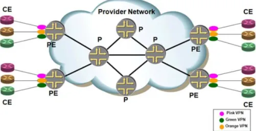
In Figure 1.3 an IP/MPLS backbone network (the packet-switched network, PSN) operated by a service provider offers a VPLS service to two VPN customers: an Orange customer and a Red
customer. Each customer has private sites that it wants to intercon-nect at the Ethernet layer. Customer sites are conintercon-nected to the SP’s backbone via attachment circuits (AC) between customer edge (CE) devices and provider edge (PE) devices. As such, a VPN can be repre-sented by a collection of CE devices. In this illustration, the Orange L2VPN N consists of<CE11, CE12, CE21, CE31, CE41>while the Red L2VPN M consists of<CE22, CE31, CE32, CE42, CE43>.
As with all PE-based VPNs, with VPLS, the CE devices are unaf-fected by the service: a VPLS CE can be a standard router, or an Ethernet bridge or host. It is the PE device that implements VPLS-specific functions. Indeed, the PE device needs to imple-ment a separate virtual forwarding instance (VFI)–also known as virtual switched instance (VSI), the equivalent of VRF tables for MPLS Layer 3 VPNs)–for every VPLS it is attached to. This VFI has physical direct interfaces to attached CE devices that belong to the VPLS, and virtual interfaces or pseudowires that are point-to-point connections to remote VFIs belonging to the same VPLS and located in other PE devices. These PWs are carried from one PE to another PE via PSN tunnels. From a data-plane perspective, different PWs in the same PSN tunnel are identified using a multiplexing field. This multiplexing field is an MPLS label. The encapsulation of the customer Ethernet frames over these MPLS connections or PWs is defined by the PWE3 working group. PSN tunnels are implemented in the provider’s network as MPLS LSPs (RSVP, LDP) or using IP-in-IP (GRE).Figure 1.4shows the protocol stack in the core of the provider’s network.
A Draft-Rosen MVPN represents itself as an emulated LAN. Each MVPN has a logical PIM interface and will form an adjacency to every other PIM interface across PE routers within the same MVPN. This is illustrated in Figure 1.__.
Note that with VPLS, a full mesh of PSN tunnels between the network’s PE devices is assumed, and for every VPLS instance there is a full mesh of pseudowires between the VFIs belonging to that VPLS. The IETF Layer 2 VPN working group has produced two sep-arate VPLS standards,0 documented in RFC 4761 and RFC 4762 (see Kompella and Rekhter, Jan. 2007, and Lasserre and Kompella, Jan. 2007). These two RFCs define almost identical approaches with respect to the VPLS data plane, but they specify significantly differ-ent approaches to implemdiffer-enting the VPLS control planes.
VPLS Control Plane
configured with the identities of all the other PE routers in a given VPLS instance, or the PE router can use a protocol to discover the other PE routers. The latter method is called autodiscovery. After discovery occurs, each pair of PE routers in a VPLS network must be able to establish pseudowires to each other, and in the event of membership change, the PE router must be able to tear down the established pseudowires. This process is known as signaling. Signaling is also used to transmit certain characteristics of the pseudowire that a PE router sets up for a given VPLS.
BGP-VPLS Control Plane
discover which remote PE routers are members of a given VPLS (autodiscovery), and for a PE router to know which pseudowire label a given remote PE router will use when sending the data to the local PE router (signaling). With the BGP-VPLS control plane, BGP carries enough information to provide the autodiscov-ery and signaling functions simultaneously. SeeFigure 1.5.
message to each PE router. A number of illustrations in the follow-ing sections elaborate on this in greater detail.
Note: Each PE router creates a virtual connection table (VCT) per VPLS instance. The VCT is similar to the virtual forwarding instance (VFI) referred to earlier in this chapter). Hence the terms VCT and VFI are used interchangeably in this chapter.
Figure 1.6 shows a JUNOS Configuration snippet describing the basic setup of a BGP-based VPLS instance. The configuration here is exactly the same as the configuration for BGP/MPLS Layer 3 VPNs, with the exception of the keyword “VPLS” defined under the protocols hierarchy, which in the case of BGP/MPLS VPNs would BGP or OSPF or RIP, etc.
Figure 1.7illustrates a two-site VPLS instance created between two PE routers clarifies the configuration statements provided above, and their relevance.
InFigure 1.7, PE2 allocates a label base of “2000” for a given VPLS instance: VPLS RED. PE3 uses label base “3000” for the same VPLS instance. The illustration that follows shows the role of the label base.
InFigure 1.8, PE2 has been allotted 3002 by PE3, as the inner label to be used to reach Site 3 on PE3. Similarly PE3 will use 2003 as the Inner label for reaching Site 2 on PE2. Another label would be used by each of the PE routers, if they needed to connect to another site within the same VPLS instance (VPLS RED) on another PE. The MPLS outer labels are also displayed in PE2’s VFT (Label 640).
If more PE routers are added to VPLS instance RED, each of them uses different label. This is illustrated inFigure 1.9.
In PE2’s VFT, site-id “1” and site-id “15” have different MPLS outer and inner labels. This indicates that those sites belong to dif-ferent PE routers. The same is the case with PE3.
LDP-VPLS Control Plane
the VPLS instance to which the LDP message refers. This is illus-trated inFigure 1.10.
LDP-VPLS and BGP-VPLS Forwarding Planes
Forwarding plane procedures, at least for unicast and to some extent for multicast (which we will see later in this chapter), are the same for BGP-VPLS and LGP-VPLS. For each VPLS, a PE VPLS data plane functions as a learning bridge and supports all the standard bridge operations, such as MAC address learning, aging, and flooding. All the pseudowires established by BGP or LDP sig-naling and the local customer edge (CE) router ports of a VPLS instance constitute the logical ports of a bridge domain.
Figure 1.9
A MAC forwarding table is created for each VPLS instance on a PE router. This table is populated using a source MAC address learning function and is used to forward unicast VPLS traffic based on the destination MAC address of the received frame. The control plane of VPLS does not need to advertise and distrib-ute reachability information; it uses address learning of the stan-dard bridge function in the data plane to provide reachability. Just like an Ethernet switch, the VPLS floods all the received Ethernet packets with unknown unicast addresses, broadcast addresses, and multicast addresses to all ports (i.e., all the ports and PWs associated with the VPLS instance.).
To forward a packet, a PE must be able to establish an MAC for-warding database (FDB). Different from the BGP/MPLS Layer 3 VPN that uses the route advertisement mechanism to establish a routing table in the control plane, the VPLS uses the standard bridge learning function to establish the FDB in the forwarding plane. The MAC address FDB is established by MAC address learning, which includes learning packets from UNI/Attachment Circuit and packets from PWs. The MAC address learning process has two parts: • Remote MAC address learning associated with PWs connected
to remote PE routers
• Local MAC address learning of the port directly connected to the user attachment circuit
The MAC learning process is shown inFigure 1.11. The process starts with a user having MAC address A and IP address “1.1.1.2” try to reach MAC address B connected to a remote PE. The ingress PE floods the packet across all PWs for the relevant VPLS instance (if the destination MAC address is unknown). In this case, one of the PE router responds to the ARP request originated by the sender’s MAC address. The ingress PE builds its MAC database with the relevant MAC-Address-PW/Remote PE for future use. The illustration also shows that another PE router, in the same VPLS instance, also builds its MAC FDB with an entry for MAC A.
Autodiscovery for LDP-VPLS
becomes an operational nightmare in a large carrier network, because of the large the number of touch-points involved in pro-visioning new sites or customers.
LDP-VPLS can now rely on BGP for autodiscovery (AD). BGP AD is a framework for automatically discovering, connecting, and main-taining the endpoints for a VPLS instance. It provides one-touch pro-visioning for LDP-VPLS where all the related PEs are discovered automatically. The service provider can use existing BGP policies to regulate the exchanges between PEs. The procedure does not require carriers to uproot their existing VPLS deployments and change the signaling protocol just to provide discovery functions.
identifier (SAFI). These numbers are allocated by the Internet Assigned Numbers Authority (IANA). A peer that announces a capability AFI 65 (L2VPN) and SAFI 25 (BGP-VPLS) is indicating support for BGP AD. The complete list of AFI and SAFI allocations can be found at these URLS: “http://www.iana.org/assignments/ address-family-numbers” and “http://www.iana.org/assignments/ safi-namespace.”
Following the establishment of the peer relationship, the dis-covery process begins as soon as a new VPLS service is provi-sioned on the PE. Two VPLS identifiers are used to indicate the VPLS membership and the individual VPLS instance:
1. VPLS-ID – membership information and a unique
network-wide identifier. The same value is assigned for all VPLS switch/forwarding instances belonging to the same VPLS. It is encodable and carried as a BGP extended community in one of the following formats:
• A two-octet AS-specific extended community
• An IPv4 address-specific extended community
2. VSI-ID – a unique identifier for each VSI/VFI, built by linking a
route distinguisher (RD) with a 4 bytes identifier (usually the system IP of the VPLS PE). It is encoded and carried as a BGP-VPLS NLRI: i.e., RD:IP.
To advertise this information BGP AD employs a simplified ver-sion of the BGP-VPLS NLRI, where just the RD and the next 4 bytes (VE ID and VE Block Offset) are used to identify the VPLS instance. There is no need for label block and label size fields, as T-LDP will take care of signaling the service labels later on. The resulting for-mat of the BGP AD NLRI is very similar to the one used for BGP/ MPLS Layer 3 VPNs, as depicted inFigure 1.12. The system IP may be used for the last 4 bytes of the VSI ID, further simplifying the addressing and the provisioning process.
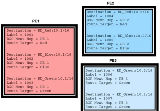
Network layer reachability information (NLRI) is exchanged between BGP peers, indicating how to reach prefixes. With VPLS, the NLRI is used to tell PE peers how to reach the VSI, rather than specific prefixes. The advertisement includes the BGP next hop and a route target (RT). The BGP next hop indicates the VSI loca-tion and in the next step is used to determine which signaling ses-sion should be employed for PW signaling. The RT, also coded as
an extended community, can be used to build a VPLS full mesh or an H-VPLS hierarchy, using BGP import/export policies. BGP is only used to discover VPN endpoints and exchange reachability information. It is not used to signal the PW labels. This task remains the responsibility of targeted-LDP (T-LDP).
Exploring the topic of T-LDP further: Two LDP FEC elements are defined in RFC 4447 (PW Setup and Maintenance Using LDP). The original PWid FEC element 128 (0x80) employs a 32-bit field to identify the virtual circuit ID and was used extensively in early VPLS deployments. The simple format is easy to under-stand, but it does not provide the required structure for the BGP autodiscovery function. To support BGP AD and other new applications, a new Layer 2 FEC Element, the generalized PWid FEC element 129 (0x81) is required.1
The generalized PWid FEC element has been designed for autodiscovery applications. It provides a field, the Address Group Identifier (AGI), that can be used to signal membership informa-tion, for example, VPLS id in the VPLS case. Separate address fields are provided for the source and target endpoints, called, respec-tively, Source Attachment Individual Identifier (SAII) and Target Attachment Individual Identifier (TAII). These are the VSI id for the two instances to be connected through the signaled PW.
The format for FEC 129 is depicted inFigure 1.13.
Each FEC field is designed as a sub-TLV equipped with its own type and length, providing support for new applications. To accommodate the BGP AD information model, the following FEC formats are used:
• AGI (type 1), which is identical in format and content with the BGP extended community attribute used to carry the VPLS-ID value
• Source AII (type 1), a 4-bytes value destined to carry the local VSI-id (outgoing NLRI minus the RD)
• Target AII (type 1), a 4-bytes value destined to carry the remote VSI-id (incoming NLRI minus the RD)
BGP is responsible for discovering the location of VSIs that share the same VPLS membership. LDP protocol is responsible for setting up the PW infrastructure between the related VSIs by exchanging service-specific labels between them. Once the local VPLS information is provisioned in the PE, the related PEs participating in the same VPLS are identified through BGP AD exchanges. A list of far-end PEs is generated and will trigger LDP-specific functions: such as the creation, if required, of
T-LDP sessions needed by these PEs and the exchange of service-specific VPN labels. The steps for the BGP AD process and the LDP session establishment and label exchange are shown inFigure 1.14. Implementations allow for PWs that are provisioned and auto-discovered manually to coexist in the same VPLS instance, that is, both FEC 128 and FEC 129 are supported. This allows autodiscov-ery to be introduced gradually into an existing VPLS deployment. Still, since FEC 128 and 129 represent different addressing schemes, it is important to make sure that just one of them is used at any point in time between the same two VPLS instances. Oth-erwise both PWs may become active, causing a loop that might cause the service to malfunction. Hence it is recommended to dis-able the FEC 128 PW in a portion of the network as soon as the FEC 129 addressing scheme is introduced there. Alternatively, a Layer 2 protocol such as RSTP may be used during the migration provide additional protection against operational errors.
Autodiscovery for LDP-VPLS – Implementation Details
This section looks at details of implementation to understand the concepts just discussed. For this purpose we are using a TiMOS (Alcatel-Lucent) specific configuration only. We are not illustrating other vendor implementations (JUNOS or Cisco IOS/XR), since the objective of this section is simply to examine the level of configuration detail required for BGP AD.
Based onFigure 1.15, let’s assume PE6 was previously config-ured with VPLS 100, as indicated by the configuration lines in the upper right. The BGP AD process will commence after PE134 is configured with the VPLS 100 instance shown in the upper left, a simple, basic BGP AD configuration. The minimum requirement for enabling BGP AD on a VPLS instance is configuring theVPLS-id and pointing toa pw-template.
topologies. In the configuration above, a VPLS instance named “Customer 1” with a service-identifier of “100” is created. BGP AD is configured along with the VPLS-ID for this instance, which is configured as “65535:100.” This is similar to the RD in the con-text of a BGP/MPLS VPN. The MTU SIZE is also set to 1478 bytes. The command “PW-Template” is defined under the top level servicecommand and specifies whether to use an automati-cally generated service distribution path (SDP). By definition, an SDP acts as a logical way of directing traffic from one PE to another through a uni-directional service tunnel.
A SDP originating on one node terminates at a destination node, which then directs incoming traffic to the correct egress ser-vice access point (SAP), as it is known in TiMOS, or UNI. The eas-iest way to refer to an SDP is to consider it as the equivalent of a PW. An SDP can be automatically created using a PW-Template or by manual configuration, wherein each VPLS customer/instance is associated with a given SDP. Two types of SDPs can be used in a VPLS deployment:
• Spoke SDP: Flooded traffic received on the spoke SDP is repli-cated on all ports within the same VPLS instance, with split horizon assumed.
• Mesh SDP: Flooded traffic received on any mesh SDP is repli-cated to all ports within the same VPLS instance, with the exception of not being forwarded on any mesh SDP.
SDP deployment is discussed further in subsequent sections. Now we will look at some commands: The command given in Figure 1.16provides the set of parameters required for establish-ing the PW bindestablish-ing described in the sections that follow.
A pw-template-bind command configured within the VPLS service under the bgp-ad subcommand is a pointer to the pw-template that should be used. If a VPLS service does not specify an import-rt list, then that binding applies to all route targets accepted by that VPLS. The pw-template-bind command can select a different template on a per import-rt basis. Further, it is possible to specify pw-templates for some route targets with a VPLS service and use the single pw-template-bind command to address all unspecified but accepted imported targets. In the con-figuration shown above, the pw-template-bind 1, binds template 1 with a set of given characteristics to a particular VPLS instance. The various command options are given inFigure 1.17.
placed in a common split horizon group to prevent forwarding between the PWs in the VPLS instances. This prevented loops that would have otherwise occurred in the Layer 2 service. However, with a VPLS service using BGP autodiscover, the service provider has the option of associating the autodiscovered PWs with a split horizon group to control the forwarding between PWs.
Once the VPN endpoints have been discovered using BGP, T-LDP is triggered. The T-LDP session between the PEs is estab-lished when one does not exist. TheFar-EndIP address required for the T-LDP identification is gleaned from the BGP AD next hop information. Thepw-templateandpw-template-bind configu-ration statements are used to establish the automatic SDP or to map to the appropriate SDP (if a PW is already established between two PE routers and a new site is coming up on one of these PEs). The FEC 129 content is built using the following values: • AGI from the locally configured VPLS-id
• The SAII from the locally configured VSI-id
• The TAII from the VSI-id contained in the last 4 bytes of the received BGP NLRI
The illustration in Figure 1.18 shows in detail the different phases of the LDP signaling path, after BGP AD is complete. It also shows how some fields can be autogenerated when they are not specified in the configuration.
Now to check a few operational commands as given in Figure 1.19: The first command displays the LDP peering relationships that have been established. The type of adjacency is displayed in the Adj Type column. In this case the type isBoth,meaning link and targeted sessions have been successfully established.
The second command, in Figure 1.20, shows the specific LDP service label information broken up according to its FEC element type, either 128 or 129. The information for FEC element 129 includes the AGI, SAII, and TAII. The SDP-ID is a number assigned to the PW or SDP between the two PE routers for the given VPLS instance.
To further understand specific topologies and their implemen-tations in regard to BGP AD, we will consider several use cases in later sections of this chapter.
Figure 1.18
Characteristics of LDP-VPLS
To enable VPLS, all PE routers connected to common VPLS customers must be able to exchange VPLS signaling information. As the number of PE routers in the network increases, scaling
this signaling component of the VPLS control plane
becomes essential.
For LDP-VPLS signaling, VPLS signaling information is exchanged by setting up a full mesh of targeted LDP sessions between each pair of PE routers that have at least one VPLS in common. A brief description of T-LDP (Targeted LDP) is provided below.
VPN services,, a remote or targeted LDP session is needed. Tar-geted LDP sessions are different because during the discovery phase, hellos are unicast to the LDP peer rather than multicast.
As the size of the VPLS network grows, the number of LDP tar-geted sessions increases exponentially on the order of O(N^2), where N is the number of LDP-VPLS PE routers in the network. Maintenance of all these LDP sessions creates an additional load on the control plane of PE routers in the VPLS network. The oper-ational challenge resulting from the O(N^2) increase in LDP ses-sions becomes even more noticeable when a service provider authenticates the sessions using Message Digest 5 (MD5) because MD5 keys must be configured on each end of every LDP session. Adding a new PE router or deleting an existing one becomes a cumbersome task because the configuration on each PE router in the network must be modified. An illustration of the full-mesh problem in LDP-VPLS is provided inFigure 1.21.
To address the control plane scaling issues in using a Flat-VPLS model as illustrated above, a hierarchy can be defined within the VPLS domain. This method of creating a hierarchy is known as H-VPLS (Hierarchical VPLS). H-VPLS tries to mitigate the full-mesh requirement by creating a two-level hierarchy of hub and spoke devices. Using an H-VPLS model, a service provider can deploy MTUs (multi-tenant units) in a multi-tenant building, with each enterprise in the beginning potentially belonging to a differ-ent VPLS VPN. The service provider then needs to aggregate the MTU traffic towards the PE device in the central office or point of presence (POP).
A traditional MTU is an Ethernet device that supports all Layer 2 switching functions, including the normal bridging functions of learning and replication on all of its ports. It is typically dedicated to one enterprise. It is also technically possible to extend the VPLS functionality to the MTUs. In this case, the MTUs act like PE devices, leading to a large number of MTUs participating in the VPLS. In a network with numerous PEs/MTUs, this leads to scal-ability limitations in terms of the number of PWs to be main-tained. Here H-VPLS can be used to introduce a hierarchy, eliminating the need for a full mesh of PWs among all participat-ing devices. Hierarchy is achieved by augmentparticipat-ing the base VPLS core mesh of PE-to-PE PWs (referred to as hub PWs) with access PWs (called spoke PWs) to form a two-tier hierarchical VPLS model, as shown inFigure 1.22.
In the illustration, the term VB stands for Virtual Bridge. Two VPLS customers are hosted on the same PE router, which acts as a virtual bridge for both customers. Spoke PWs are created between the MTUs and the PE routers. The hub PW is the PWs between PE routers in the core. These are typically mesh SDPs.
H-VPLS offers certain operational advantages by centralizing major functions (e.g., VPLS end-point autodiscovery, participat-ing in a routed backbone, maintainparticipat-ing a full mesh of tunnel LSPs, and multiple full meshes of PWs) in the POP PE routers. This makes it possible to use lower-cost, low-maintenance MTU devices, thereby reducing the overall capital expenditure and operating expenses, since typically there are an order of magni-tude more MTU devices than PE routers. Another operational advantage offered by H-VPLS along with BGP AD, is centralized provisioning, which means fewer elements to touch when uple-veling service for a customer. Adding a new MTU device requires some configuration of the local PE router but does not require any signaling to other PE routers or MTU devices, thereby simplifying the provisioning process.
In H-VPLS, a CE is attached to an MTU through an attachment circuit. An AC from a specific customer is associated (by configu-ration) with a virtual bridge dedicated to that customer within the considered MTU. An AC may be a physical or a virtual LAN (VLAN) tagged logical port. In the basic scenario, an MTU has one uplink to a PE. This uplink contains one spoke PW (spoke SDP) for each VPLS served by the MTU. The end points of this spoke PW are an MTU and a PE. As in the illustration above, the uplink between MTU1 and PE1 carries two PWs because MTU1 has two VPLS customers attached.
Use Cases for LDP-VPLS and BGP AD
Full-Mesh VPLS
The full mesh is likely the most common VPLS topology deployed today. It provides a full mesh of direct connections among all nodes in a VPLS. It is also the simplest to configure for BGP AD. This provides a logical starting point on which other configurations can build. In the diagram inFigure 1.23, BGP AD is used to connect MTUs1, PERs4, and MTUs2 in a full mesh. The VPLS service VPN200 instantiated on the three nodes.
The BGP AD configuration on all three nodes participating in VPN 200 is very similar. The service difference is the port on which the access port or UNI (referred to as SAP in TiMOS) is configured. Therefore only the configuration for MTUs1 is presented in Figure 1.24.
Figure 1.23
The standard SDP show commands are used to view the rela-tionship of the service to the SDP, regardless of whether they were created automatically, following the BGP AD process, or manually. SeeFigure 1.26.
The LDP binding command has been extended to include the Generic PWid FEC Element 129 (0x81). This display includes all the LDP specific attributes for the VPLS instance, including the AGI, SAII, and TAII signaling options. SeeFigure 1.27.
Specific L2VPN AD routes are stored in the BGP RIB IN and RIB OUT tables. MTUs1 receives two L2VPN AD routes for VPN 200 for PERs4, one advertised from each route reflector. Only one of these will be actively used. To determine the L2VPN AD routes adver-tised from MTUs1 (RIB OUT), the local loopback address is used as the prefix. SeeFigure 1.28.
Mixed FEC 128 and FEC 129 Configurations
Numerous cases may require carriers to mix manually config-ured endpoint environments with discovered Layer 2 services using BGP AD. Some of these may include:
Figure 1.26 Checking the SDP
• H-VPLS solutions where the carrier does not want to deploy BGP to the edge nodes but still wants the benefits of MPLS to the edge
• Mixed operational models used by different operational bodies inside the same carrier
• During a migration from manually provisioned services to a discovered operational model
Let us look at the case study inFigure 1.29.
In this example, VPN 100 uses the H-VPLS solution. Manually configured PWs connect the MTU nodes to the PE nodes, and BGP AD is used to build the full mesh between the PE-rs nodes. PERs4 contains both the PWid FEC Element 128 (0x80) and the General-ized PWid FEC Element 129 (0x81). MTUs1 uses the standard con-figuration for a VPLS, including the SDP and the service definition. SeeFigure 1.30.
As stated earlier, PERs4 includes the manual service con-figuration for VPN 100 facing MTUs1 and for BGP AD facing the other nodes in the full mesh. The standard configuration for the FEC-128-only node (MTUs1), is highlighted in red in Figure 1.31.
The other two nodes participating in the VPN 100 full mesh only require BGP AD. Here PERs6, PERs4, and MTUs2 have a full mesh of PW among them, and MTUs1 is only connected to PERs4. SeeFigure 1.32.
Now to look at some operational commands: The basic service display command has been extended to include the BGP AD ser-vice information and any automatically generated SDP. See Figure 1.33.
Figure 1.30 MTU Configuration
The standard SDP show commands are used to view the rela-tionship of the service to the SDP, regardless of whether they were created automatically, following the BGP AD process, or manually. SeeFigure 1.34.
The LDP binding command has been extended to include the Generic PWid FEC Element 129 (0x81). This display includes all the LDP specific attributes for the VPLS instance, including the AGI, SAII, and TAII signaling options. SeeFigure 1.35.
H-VPLS Configurations
Figure 1.36
The display output for VPN 300 is from the perspective of PERs4. No SDP connection between PERs4 and MTUs2 is dis-played. Similarly, there is no connection between MTUs1 and PERs6. Since there are no common import/export between these pairs of nodes, there is no automatically established SDP. See Figures 1.41and1.42.
Taking a slightly different approach, we can explore the L2VPN routes advertised from PERs4 (RIB OUT from IP address 1.1.1.4/ 32). PERs4 sends L2VPN AD routes to each route reflector server. Each of those route reflectors propagates that information to all of its I-BGP clients. Each of the receiving client’s I-BGP peers deter-mines whether or not to accept the L2VPN route, based on match VPLS-id and a corresponding import route target. To determine the L2VPN routes received by PERs4 from other peers (RIB IN), the specific remote peers /32 prefix is used. PERs4 imports and exports two route targets: 65535:348, which corresponds to MTUs1, and 65535:300, which corresponds to the full mesh to which PERs6 belongs. However, since BGP reflects information to all peers equally, all BGP peers would receive these advertisements—in this case, one from each route reflector. However, only those specifically configured with the VPLS-id and matching import route target would install the routes and trigger complimentary actions, like T-LDP sessions and service label exchanges. SeeFigure 1.43.
Hub and Spoke VPLS Configurations
backhaul case, the carrier can select different PE nodes to switch traffic rather than building direct logical connections. For exam-ple, all CPEs connections to the same PE can communicate directly. However, the different PEs would communicate through a central hub PE, rather than building a logical full mesh, thus emulating an H-VPLS model.
InFigure 1.44, MTUs1 and MTUs2 are logically connected to PERs4 via PWs (spoke SDPs), even though MTUs2 is physically connected to PERs6. Therefore both the MTUs’s would learn about other sites (MAC addresses) only via PERs4. This is also the case for any sites connected via PERs6. Similarly, traffic for-warding would also be via PERs4 only.
Figure 1.44
PERs4 and the two MTU nodes. The MTUs nodes do not connect directly because each one only imports the route target exported by the hub, i.e., “65535:401.” The various operational commands are given inFigures 1.47, 1.48, 1.49, and1.50.
Figure 1.47 Checking the Service ID
The L2VPN routes received by PERs4 from other peers (RIB IN) are determined using the specific remote peers /32 prefix. PERs4, the hub, imports the route target 65535:400, which is being exported by all the spokes. In Figure 1.51 we can see which L2VPN routes were received from MTUs1.
potentially affect the data plane scalability. In certain topologies, even MPLS provider routers would need to act as hub sites. This is true when the MTU devices act only as Layer 2 switches and the PE routers host VPLS instances. See the illustration inFigure 1.52to understand this further.
LDP-BGP VPLS Interworking
Currently, both LDP-VPLS and BGP-VPLS are widely deployed in service provider networks. Two key business drivers for LDP-BGP VPLS interworking are the need to extend the VPLS net-works—and therefore to also be able to scale them.
Scaling the VPLS Network
As the VPLS network expands, the LDP-VPLS control plane does impose certain scalability concerns as discussed in the ear-lier sections. In comparison, the BGP-VPLS control plane more easily enables the VPLS network to scale to support new VPLS cus-tomers and to include more sites for existing VPLS cuscus-tomers. One option for scaling the VPLS network, when there is an existing LDP-VPLS deployment, is to abandon the LDP-VPLS control plane entirely and transition the VPLS network to the BGP-VPLS control plane. However, this approach may not be feasible for a number of reasons, two of which are:
• Legacy PE routers may not support a BGP signaling mecha-nism, and for financial reasons, replacing the existing PE routers may not be a viable option.
• Operating overhead and possible disruption to the VPLS net-work for existing customers may not justify this transition. Another option for scaling VPLS when there is an existing LDP-VPLS deployment is to cap the existing LDP-LDP-VPLS deployment and to expand the VPLS network using the BGP control plane. With this approach, the LDP- and BGP-VPLS control planes, including the signaling mechanisms, must coexist in the network, which requires some interworking between the two control plane mechanisms.
To be able to offer a regional or national VPLS network, service providers are seeking scalable ways to extend the reach of VPLS beyond a single LDP-VPLS metro domain. One mechanism is the use of BGP-VPLS in the Wide Area Network (WAN) to intercon-nect multiple LDP-VPLS metro domains. This approach requires a new inter-domain technique, since the existing defined solutions for multiple ASs require that all domains run the same signaling protocol. One of the critical requirements for such a deployment model is ensuring that the existing PE routers in the metro domains that are running the LDP-VPLS control plane do not require any changes or upgrades. A second requirement is the extension of VPLS without significant additional load on the control plane of the LDP-VPLS PE routers in the metro network. LDP-BGP VPLS interworking meets the above requirements and enables service providers to use a single protocol, BGP, in the WAN to offer multiple MPLS VPN services, including VPLS and Layer 2 and Layer 3 VPNs. Moreover, because a single protocol is used, provisioning the system can provide operating efficiency.
With basic LDP-BGP VPLS interworking, newly added PE routers in the network support both the LDP and BGP control planes, including the corresponding signaling mechanisms required. These new PE routers use the BGP-VPLS control plane when communicating with each other, and use the LDP-VPLS control plane to communicate with the existing PE routers, which run LDP-VPLS.
BGP-VPLS and LDP-VPLS control planes. They use the BGP-VPLS control plane among themselves for autodiscovery and for signal-ing, establishing an internal BGP (IBGP) session among them-selves or via a route reflector. They also use LDP-VPLS signaling to communicate with the LDP-VPLS-only routers, establishing LDP sessions with the existing PE routers. For all VPLS customers that have sites on only the existing LDP-VPLS PE routers or the newly added BGP-VPLS PE routers, VPLS is set up using a single control plane and a single signaling protocol.
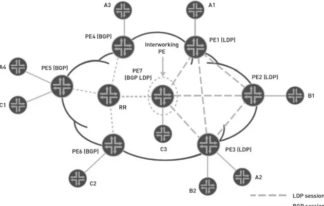
The LDP-BGP VPLS model employs two groups of PE routers. All PE routers in the first group run only the LDP-VPLS control plane among themselves, whereas all PE routers in the second group run only the BGP-VPLS control plane among themselves. These two groups are interconnected through a single PE router, referred to as the interworking PE router, which runs both LDP-VPLS and BGP-LDP-VPLS control planes. The illustration in Figure 1.53shows how the LDP-VPLS network is expanded using the BGP control plane in a scalable model.
In this illustration, the PE1, PE2, and PE3 routers are existing PE routers supporting only the LDP-VPLS control plane. The newly added PE routers (PE4, PE5, and PE6) support the BGP-VPLS con-trol plane. The PE7 router is the interworking PE router, supporting both LDP and BGP control planes and the interworking between them. While the existing LDP-VPLS PE routers and the newly added BGP-VPLS PE routers are isolated into two groups, the PE7 router is part of both groups and plays the vital role of interconnecting them. For example, VPLS Customer A has multiple sites in both the LDP- and BGP-VPLS groups. Customer A’s sites A1 and A2 are con-nected to the LDP PE routers, and sites A3 and A4 are concon-nected to the BGP PE routers. PE7 router provides the LDP-BGP VPLS inter-working function and stitches together the pseudowires created by the signaling components of the two different control planes. PE routers in the BGP-VPLS group are provisioned only for the BGP-VPLS control plane. From their perspective, the interworking PE router (PE7) is a standard BGP-VPLS peer, and they are unaware of the PE routers in the LDP-VPLS group. Legacy PE routers in the LDP-VPLS group are provisioned only for the LDP-VPLS control plane. From their perspective, the interworking PE router (PE7) is a standard LDP-VPLS peer, and they are unaware of the PE routers in the BGP-VPLS group.
Containing all the existing LDP-VPLS PE routers in a single group caps the LDP-VPLS deployment and allows network expan-sion to occur in the BGP-VPLS group without creating additional control plane or data plane overhead on existing LDP-VPLS PE routers. This eliminates a fundamental problem with the previous method: that all BGP-VPLS PE routers had to also operate in the LDP-VPLS control plane. However, in some network designs, con-taining all the LDP-VPLS PE routers in a single group may not be feasible because of geographical limitations or other administra-tive reasons. In such environments, multiple groups of PE routers can be running the LDP-VPLS control plane and a single group of PE routers can be running the BGP-VPLS control plane, which interconnects all the LDP-VPLS control plane groups through multiple interworking PE routers.
The basic LDP-BGP VPLS interworking method requires min-imal configuration changes on the existing LDP-VPLS PE routers. However, new PE routers added as part of the network expansion must support both LDP-VPLS and BGP-VPLS. The support pro-vided by the new PE routers is essential for basic LDP-BGP VPLS interworking to succeed. Because the new PE routers support both LDP-VPLS and BGP-VPLS, they can establish pseudowires using both the LDP and BGP signaling mechanisms. These pseu-dowires can be created for VPLS customers with sites attached to both existing LDP-VPLS routers and the newly added BGP-VPLS routers. A full mesh of pseudowires is created between the existing LDP-VPLS PE routers and the newly added BGP-VPLS PE router. As a result, data plane operations on all PE routers adhere to the split-horizon forwarding rule, and the VPLS traffic is not switched between pseudowires. Additionally, no changes are required to the existing LDP or BGP control plane procedures themselves.
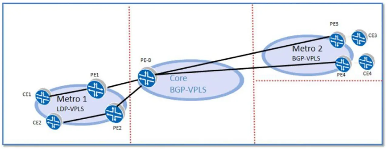
Case Study – Connecting LDP- and BGP-VPLS Metro Domains
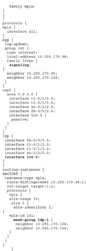
Let us look at a sample case study of two metro domains, one using LDP-VPLS and the other using BGP-VPLS, being intercon-nected via a BGP-VPLS interworking PE, as shown inFigure 1.55. The configurations required to enable this are based on JUNOS.We start with the CE router configuration. The only configura-tion needed here is the interface and IP subnet details. See Figure 1.56.
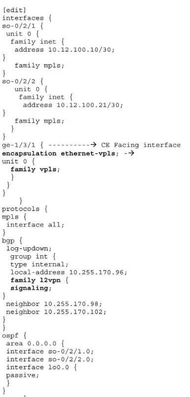
Router PE3 is configured for VPLS by configuring BGP, MPLS, OSPF, and LDP. (These protocols are the basis for most Layer 2 VPN-related applications, including VPLS.) The configuration includes the signaling statement at the [edit protocols bgp group
group-namefamily l2vpn] hierarchy level.
Looking at this in more detail: The command “encapsulation VPLS” is used on Ethernet CE-facing interfaces that have VPLS enabled and are supposed to accept packets carrying standard Tag Protocol ID (TPID) values. If the interface needs to accept VLAN (Tagged) packets, then encapsulation “vlan-vpls” is to be used. The family “vpls” statement enables the interface with the VPLS address family. The statement “family l2vpn signaling” enables BGP signaling for VPLS. All services (L2VPN, L3VPN, VPLS, etc) are configured under the routing-instances hierarchy. Figure 1.56 Router CE3 Configuration
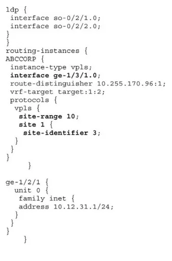
In this case, a VPLS instance named “ABCCORP” is configured along with the RD and VRF targets. BGP-VPLS relies on route tar-gets for discovery and the association of a remote PE to an instance. The same procedure is used as in BGP/MPLS VPNs. The “site-range” defines the number of sites that can exist in a VPLS instance. The site-name is a generic name and can be used to identify the site. The site-id configured on each PE needs to be unique per VPLS domain. Each site within a given PE participating in the same VPLS instance needs a unique site-id as well. See Figure 1.57.
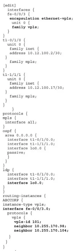
Router PE4’s configuration would identical to PE3’s, except for its unique site-id, RD, and RT, so there is no need to illustrate it. The key element in this system, the interconnect PE router, PE-B, is configured to connect the BGP and LGP-VPLS domains. Its configuration has two portions, both defined under the VPLS instance “ABCCORP.” The first portion is router PE-B’s tion in the BGP-VPLS domain, the second portion is its participa-tion within the LDP-VPLS domain. The command “vpls-id” identifies the virtual circuit identifier used for the VPLS routing instance. This statement is part of the configuration to enable LDP signaling for VPLS. The VPLS-ID needs to be the same for all PE routers for the same VPLS instance, and therefore needs to be globally unique.
A bit of recap here: We have seen that a single VPLS routing instance can encompass one set of PE routers that use BGP for sig-naling and another set of PE routers that use LDP for sigsig-naling. Within each set, all of the PE routers are fully meshed in both the control and data planes and have a bidirectional pseudowire to each of the other routers in the set. However, the BGP-signaled routers cannot be directly connected to the LDP-signaled routers. This where the interconnect/border PE router comes in.
In the control plane, each fully meshed set of PE routers in a VPLS routing instance is called a PE router mesh group. The bor-der PE router must be reachable by and have bidirectional pseu-dowires to all of the PE routers that are a part of the VPLS routing instance, both the LDP-signaled and the BGP-signaled routers. To configure LDP-BGP interworking for VPLS, the mesh group state-ment is included in the VPLS routing instance configuration of the PE border router, as illustrated in the configuration below. The “neighbor” statement identifies each LDP-VPLS PE statically and builds PWs to each of them.
Figure 1.57 Router PE3 Configuration
BGP-signaled mesh groups. When forwarding any VPLS traffic received over a PE router’s pseudowire, the border router assures that traffic is not forwarded back to the PE routers that are in same mesh group as the originating PE router.
network. When the interconnect PE receives the data, it won’t find the MAC address in its MAC table and so it will flood the frame to all the BGP-VPLS PE routers and LDP-VPLS PE routers in Mesh-Group2, but not back to Mesh-Group1. The PE routers will then perform a MAC-table lookup and flood the data to their CE routers. SeeFigure 1.58.
Now let us move on to the configurations of the LDP PE routers, beginning with PE1. The configuration does not include any BGP-specific statements or any mesh group definitions. Only the “vpls-id” and “neighbor” statements are used. Router PEB is also configured to participate in the LDP-VPLS instance. See Figure 1.59. PE2’s configuration is identical to that of PE1, and hence is not illustrated.
The command inFigure 1.60can be used to validate and verify the BGP and LDP interworking state on PEB.
Figure 1.58 Router PEB Configuration
Multicast Traffic in VPLS
In each VPLS routing instance, it is possible to configure a ded-icated point-to-multipoint (P2MP) LSP to carry all unknown uni-cast, broaduni-cast, and multicast traffic. Enabling this feature increases the efficiency of the network because duplicate copies of flooded traffic do not have to be created for each PE router in the VPLS routing instance.
Figure 1.61shows how flooded traffic reaches PE routers in a VPLS routing instance when a P2MP LSP is not configured for flooding. In this diagram, PE1 needs to forward 100 Mbps of mul-ticast traffic. Since there are three recipient PE routers (PE2, PE3, and PE4), PE1 creates three copies of traffic, which now becomes 300 Mbps in bandwidth. P1 also sends 200 Mbps of traffic towards P2, since PE2 and PE3 are behind P2, and sends one copy (100 Mbps) towards PE4. Finally, P2 sends the traffic (a copy each) to the receivers, PE2 and PE3.
In a large network with high volumes of multicast, unknown unicast/broadcast traffic this can be a very costly affair, since the bandwidth consumption is so high.
In contrast, if the VPLS instance is configured to use a P2MP LSP, the ingress PE router creates a single copy of the unknown traffic that needs to be flooded, and each node in the P2MP LSP path creates a single copy for its respective branch nodes. This applies throughout the network. As illustrated inFigure 1.62, this means a huge reduction in bandwidth utilization and offers signif-icant cost savings to the operator.
Let us take a look at some sample configurations, based on JUNOS inFigure 1.63. In the first configuration, a P2MP label-switched template has been associated with the VPLS instance.
Figure 1.62
The configurations inFigures 1.64 and1.65show commands for viewing the association of the P2MP LSP with the VPLS instance. The first command displays the BGP table with all the route information for PE routers that are part of the same VPLS instance. The second command shows details of the VPLS instance.
Selective Trees for Multicast in VPLS
One of the issues that needs to be addressed when creating a P2MP tree in the context of VPLS is how to handle multicast flood-ing, which still delivers traffic to PE routers that do not have any interested receivers. The solution is to use Inclusive P-Tunnels. While the present model does offer extremely significant band-width savings, the need for more optimal multicast delivery always exists.
The Internet draft “draft-ietf-l2vpn-vpls-mcast-08.txt” specifies procedures for delivering multicast traffic for VPLS, including the use of selective trees. Some passages from the draft are quoted here:
Once a PE decides to bind a set of VPLSes or customer multicast groups to an Inclusive P-Multicast tree or a Selective P-Multicast tree, it needs to announce this binding to other PEs in the network.
This procedure is referred to as Inclusive P-Multicast tree or Selective P-Multicast tree binding distribution and is performed using BGP. If an Inclusive P-Multicast tree is used to instantiate the provider tunnel for VPLS multicast on the PE, the advertising PE MUST advertise the type and the identity of the P-Multicast tree in the PMSI Tunnel attribute.
Selective trees provide a PE the ability to create separate P-Multicast trees for certain<C-S, C-G>streams. The source PE, that
originates the Selective tree, and the egress PEs, MUST use the Selective tree for the<C-S, C-G>streams that are mapped to it.
This may require the source and egress PEs to switch to the Selective tree from an Inclusive tree if they were already using an Inclusive tree for the<C-S, C-G>streams mapped to the Selective
tree. Once a source PE decides to setup an Selective tree, it MUST announce the mapping of the<C-S, C-G>streams (which may
be in different VPLSes) that are mapped to the tree to the other PEs using BGP. After the egress PEs receive the announcement they set up their forwarding path to receive traffic on the Selective tree if they have one or more receivers interested in the<C-S,
C-G>streams mapped to the tree. Setting up the forwarding path
requires setting up the de-multiplexing forwarding entries based on the top MPLS label (if there is no inner label) or the inner label (if present). The egress PEs MAY perform this switch to the Selective tree once the advertisement from the ingress PE is received or wait for a preconfigured timer to do so, after receiving the advertisement, when the P2MP LSP protocol is mLDP. When the P2MP LSP protocol is P2MP RSVP-TE an egress PE MUST perform this switch to the Selective tree only after the advertisement from the ingress PE is received and the RSVP-TE P2MP LSP has been setup to the egress PE. This switch MAY be done after waiting for a preconfigured timer after these two steps have been accomplished. A source PE MUST use the following approach to decide when to start transmitting data on the Selective tree, if it was already using an Inclusive tree. A certain pre-configured delay after advertising the<C-S, C-G>streams mapped to an Selective tree,
the source PE begins to send traffic on the Selective tree. At this point it stops to send traffic for the<C-S, C-G>streams, that are
mapped on the Selective tree, on the Inclusive tree. This traffic is instead transmitted on a Selective tree.
Inter-Provider VPLS
Inter-provider VPLS makes it possible for a service provider to serve an entirely new set of customers, such as international businesses who have sites spread over a very large geographic area and are served by multiple ISPs. By establishing VPLS part-nerships with other service providers outside of the service pro-vider’s own service region, the footprint of the propro-vider’s own VPLS offering is expanded. These partnerships can be negotiated based on known customer needs or on projected customer bases in the shared regions. For the customer, the inter-provider peer-ing is transparent; each of the customer’s sites still appears to be connected to a shared Ethernet switch. Inter-provider VPLS also opens a potential new source of revenue for carriers with large regional or global MPLS networks by providing a wide-area VPLS backbone for regional or local VPLS service providers. For both metro Ethernet providers wanting to develop direct VPLS part-nerships with other metro Ethernet providers and carrier want-ing to provide a VPLS backbone to metro Ethernet providers, creating an inter-provider VPLS network requires underlying protocols that allow VPLS to span one or multiple autonomous system boundaries.
Discovery
A PE is configured to know what VPLS sites, or instances, it is connected to. But for each of its configured VPLS instances, it must have some way of knowing which PEs are a part of the same VPLS instance. That is, if a PE has a local interface connected to VPLS 1, it must know which other PEs have interfaces to VPLS 1. Thus the final requirement for a practical VPLS implementation is discovery.
When LDP is used as the VPLS signaling protocol, no discovery mechanism is supported within the protocol itself. Each PE must be individually configured with the identities of all other PEs belonging to each VPLS instance, and every time an instance is changed (a PE is added or deleted, or an entire instance is added or deleted) each PE must be reconfigured. Touching each PE for every change quickly becomes operationally prohibitive for a commercially viable VPLS offering, and it can also significantly increase the potential for configuration errors in the network.
the complexity and risk. MP-BGP, on the other hand, enables auto-discovery as a part of its VPLS procedures. The same protocol can be used for both signaling and autodiscovery, reducing complex-ity while at the same time simplifying changes to VPLS instances. The previous section ended with an example of how imple-menting VPLS with MP-BGP is preferable to impleimple-menting with LDP: MP-BGP offers a means of performing autodiscovery to sim-plify the management of VPLS instances without requiring the addition of new protocols and procedures, and LDP does not. But there are many more reasons for using MP-BGP to implement VPLS. This section shows why MP-BGP VPLS is the superior solu-tion for large-scale VPLS deployments, even within a single Autonomous System (AS); for inter-provider VPLS, it is the only practical solution.
Common Inter-AS Procedures
As we have seen in the previous sections, BGP-based VPLS is preferable to LDP-based VPLS for any serious service offering because of its autodiscovery capabilities, its ability to support multiple services, and its superior scalability. These qualities hold when the VPLS service offering spans only a single AS. But when a commercially viable VPLS offering must span multiple ASs, BGP-based VPLS is no longer merely the best solution; it is the only practical solution.
The fundamental role of BGP is, after all, inter-AS routing. The autodiscovery, the multiprotocol (and hence multiservice) sup-port, and the practical scaling capabilities of MP-BGP can there-fore be easily extended across AS boundaries. Further, using a single group of common procedures means that engineers do not have to design a separate logical infrastructure for interprovi-der VPLS, and that operations personnel are not burdened with additional complexity (and risk). Specifically, BGP-based VPLS supports the same three inter-AS design options as do Layer 3 BGP/MPLS VPNs. These three options are referred to throughout the industry as Options A, B, and C.
Option A
example, ASBR1 sees itself as a PE and sees ASBR2 as a connected CE; conversely, ASBR2 sees itself as a PE and sees ASBR1 as a connected CE.
This relationship means that the connecting medium between the ASBRs must be Ethernet, which can be a limiting factor: ASBRs must be co-located or at least geographically close enough to accommodate the distance limitations of a physical Ethernet link. On the other hand, Option A is the only option that does not require an LSP between the two ASs, which might be a consider-ation should the operators of the two ASs wish to completely iso-late their MPLS topologies from each other. The key limiting factor of Option A, however, is the fact that the ASBRs are, for all practical purposes, PEs. This breaks the desired VPLS model in four respects:
native Ethernet, where the frames are re-encapsulated in MPLS and forwarded to their destination.
• Since the ASBRs are PEs, they maintain VPLS state. Specifically, they must perform learning and record MAC addresses and ports, which limits the number of VPLS instances they can sup-port. The growth of the inter-AS VPLS service is then subject to the same limitations.
• For each VPLS instance on the ASBRs, a separate VLAN instance must be established between the ASBRs. For example, if there are 100 VPLS instances, 100 separate VLANs between the ASBRs must be established and maintained.
• Because the logical relationship on each side of the AS bound-ary is that of a PE to a CE, the ASBRs on each side must be con-figured as PEs. The autodiscovery capability of BGP-based VPLS is lost, and operational overhead increases accordingly.
Option B
Option B eliminates the maintenance of VPLS state in the ASBRs. A single EBGP session between the ASBRs signals VPLS, and VPLS traffic can be carried on a single LSP between the ASBRs. No PE functions such as MAC learning and VPLS state mainte-nance are required in Option B, making it much more scalable than Option A. SeeFigure 1.67.
Option C
Option C moves the EBGP session endpoints from the ASBRs to the PEs themselves, using multihop EBGP. This option is consid-ered the most scalable of the three because no VPLS-related con-figuration is required on the ASBRs at all. The VPLS topology between ASs remains the same as it is within a single AS: All “VPLS intelligence” is in the PEs connecting VPLS sites, and the network core is “VPLS unaware.” Option C can be made even more scalable by leveraging BGP’s route reflector capabilities. Rather than estab-lish multihop EBGP sessions between individual PEs, the sessions can be established between route reflectors. This accords the same scaling benefits in inter-AS VPLS as in single-AS VPLS that uses route reflectors. SeeFigure 1.68.
Conclusion
2
UNDERSTANDING ADVANCED
MPLS LAYER 3 VPN SERVICES
Introduction
The previous chapter discussed the building blocks of deploy-ing Ethernet-based multipoint services. In this chapter we look at the deployment scenarios of MPLS Layer 3 VPNs.
MPLS Layer 3 VPNs
RFC 2547bis defines a mechanism that allows service providers to use their IP backbone to provide VPN services to their cus-tomers. RFC 2547bis VPNs are also known as BGP/MPLS VPNs because BGP is used to distribute VPN routing information across the provider’s backbone and because MPLS is used to forward VPN traffic from one VPN site to another.
The primary objectives of this approach are as follows: • Make the service very simple for customers to use even if they
lack experience in IP routing
• Make the service very scalable and flexible to facilitate large-scale deployment
• Allow the policies used to create a VPN to be implemented by the service provider alone, or by the service provider working together with the customer
• Allow the service provider to deliver a critical value-added service that galvanizes customer loyalty
Network Components
In the context of RFC 2547bis, a VPN is a collection of policies, and these policies control connectivity among a set of sites. A cus-tomer site is connected to the service provider network by one or more ports, where the service provider associates each port with a
VPN routing table. In RFC 2547bis terms, the VPN routing table is called a VPN routing and forwarding (VRF) table.
Figure 2.1 illustrates the fundamental building blocks of a BGP/MPLS VPN.
Customer Edge (CE) Routers
A customer edge (CE) device provides customer access to the service provider network over a data link to one or more provider edge (PE) routers. While the CE device can be a host or a Layer 2 switch, typically the CE device is an IP router that establishes an adjacency with its directly connected PE routers. After the adja-cency is established, the CE router advertises the site’s local VPN routes to the PE router and learns remote VPN routes from the PE router.
Provider Edge (PE) Routers
PE routers exchange routing information with CE routers using static routing, RIPv2, OSPF, or EBGP. While a PE router maintains VPN routing information, it is only required to maintain VPN routes for those VPNs to which it is directly attached. This design enhances the scalability of the RFC 2547bis model because it eliminates the need for PE routers to maintain all of the service provider’s VPN routes.
Each PE router maintains a VRF for each of its directly con-nected sites. Each customer connection (such as Frame Relay PVC, ATM PVC, and VLAN) is mapped to a specific VRF. Thus, it