SHORT RANGE
TV
TRANSMITTER
(AMATEUR TV TRANSMITTER)
SUK
RI
BTN SHEIKH
SALTMULLAH
11<
UNIVE
R
SITJ MALAY: IA
SARA
WAK
6630 S948
Borang Penyerahan Tesis Universiti Malaysia Sarawak
Rl3a BORA G PE YERAHAN TESIS
Judui
SHORT RA
G
E TV TRANSMITTER (A TV TRANSMlTTER)
SESI PENGAJIA
: 2001
/2002
Saya SUKRJ BIN SHEIKH SALlMULLAH(HURUF DESAR)
mengaku membcnarkan tesis ini disimpan di Pusat Kh.idmat Maklumat Akadcmik, Un.iversiti Malaysia Sarawak dengan syarat-syaral kegunaan seperti bcriku!:
1. Hakmilik kertas projek adalah di bawah nama penulis melainkan penulisan sebagai projek bersarna dan dibiayai oleh UNIMAS, hakmiliknya adalah kepunyaan UNIMAS.
2. Naskhah salinan di dalam bcntuk kertas alau mikro hanya boleh dibuat dengan kebcnaran bertulis daripada penulis.
3 Pusat Khidmal Maklumat Akadem.ik. UNIMAS dibcnarkan membual salinan Illlluk pengajian mercka. 4. Kertas projek hanya boleh diterbiikan dengan kcbertaran penulis. Bayaran royalti adalah mcngikut
kadar yang dipcrsclujlli kelak.
5. ' Saya mem6eft8fkA II/tidak membenarkan Perpustakaan mcmbuat salinan kenas projck ini sebagai bahan pertukanm di antara instirusi pengajian tinggi.
6 . •• Slla tandakan (,/)
r = J SULlT (Mengandungi maklwnat yang berda~ah keselamatan atau kcpenringan Malaysia sepcrti yang tennaklub di dalam AKTA RAHSIA RASMI 1972) r = J TERHAD (Mengandungi maklumat TERHAD yang Idah ditenlUkan olch organisasiJ
badan di mana penyelidikan dijalankan)
rn
TIDAK TERHADDi altkan oleh )
lv
----r.
~ .(TANDATANGAN PENUUS) [IANUATANG AN PEl'.'YUIA) Alamat Tetap: LOT 2863 LORONG
MELA TI I, FASA 3, KAMPUNG EN. WAN AZLAN B. WAN ZAINAL ABIDIN ASSY AKIRIN. 97007 BINTULU,
SARAWAK. Nama Pcnyelia
Tarik b: _.d.5-,J1J.J",N,-2",0",0u,2~_ __ __ _ Tarikb: 5 JlIN 2002 CATATAN
•
..
Potong yang I id:lk ~rkenaanJika kert"s Projck ini SULIT alau TERHAD, sila lampirkan surat daripada pihak berkuasM orgallisasi berkellaan dengan menycrtakan sekali tempoh kertas projek. Ini pcrlu dikelaSkan sebagai SUUT atou TERHAD.
SHORT RANGE TV TRANSMJTTER
(
AMATEUR
T
V
TRANSMITTER)
S
U
KRI BIN
SH
EIKH
S
ALIMULLAH
Tesis Dikemukakan Kepada
Faku lti Kejuruteraan, Unil'ersili Malaysia Sarawak Sebagai Memenuhi Sebahagian daripada Syarat
Penganugerahan Sarjana Muda Kejuruteraan
Dengan Kepujian (Kejuruleraan Elektronik dan Telekomunikasi) 2002
Untuk ayah, ibu, dan abang'abang tersayang.
PE
G
I-I
ARGAAN
Dengan Nama ALLAH Yang Maha Pem urah Lagi Maha Mengasihani. Segala puji dan syukur dirafa'kan ke hadraL·Nya kerana dengan izin·Nya, projek ini dapaL dilaksanakan se rta diselesaikan dengan baik.
Oi sini, penulis ingin merakamkan penghargaan ikhlas kepada penyelia Lesis. 8n. Wan Azlan di aLas segala bimbingan, perbincangan, sokongan, di samping komiLmennya sepanjang penyeJidikan Lesis ini.
1'idak dilupai, En. Wan Abu Bakar, KeLua Makmal ElckLronik, kerana aLas usahanya dalam me mberikan panduan dalam me njayakan projek ini.
8n. Thelaha Masri, juga diucapkan tcnma kasih aLas nasi hat Leknikal, sebagai sokongan kepada penyelia Lesis yang dihormati.
Penghargaan juga dit.ujukan kepada mana-mana pihak yang memhantu daJam projek ini sama ada secara langsung atau tidak.
ABSTRACT
Amateur TV Transmitter (Short Range) is actually a kind of broadcasting equipment t.hat is very useful for broadcasting event involving a coverage area of
less than 10 miles and on the other hands, it is portable and this will make the process of assembling the equipment becoming much faster. The frequency being
used is in the UHF (Ultra High Frequency) range, 477.25 MHz based on the crystal that is used and at frequency which would not interfere the L'Ommercial
broadcasting frequency through negotiation with the Malaysia Radio and
Television (RTM). For the usage in UNlMAS, this system may be used for live telecast (wireless) during the Convocation event to the Lecture J-fall 1 (DKJ) so this will enable other students to see the event. Besides, fhi~ system could also be allplieci to remole control aircraft and unmanned car, as the visualization agent.
ABSTR
AK
Pema ncarTV Amatur (Jarak Dekat) adalah merupakan se]enis peralatan sisLem
pemancar siaran yang amat berguna bagi penyiaran yang melibatkan satu kawasan liputan yang kurang daripada 10 batu serta antara lainnya, rnudah untuk dibawa dan ini rnempercepatkan proses persediaan penyiaran. Frekuensi
yang digunakan aelalah dalam julat UHF (Frekuensi Ultra Tinggi) iaitu 47725
MHz berdasarkan kepada nilai krislal yang cligunakan dan pada frekuensi yang
tidak akan oJengganggu frekuensi penyiaran komersil melalui perundingan dengan pihak RTM. Dari seg; penggunaannya eli UNIMAS, sistem ini boleh digunakan bagi penyiaran siaran langsung Majlis Konvokesyen (tanpa wayar) ke Dewan Kuliah I agar para pelajar yang lain dapat menynksikan Illfljlis
konvokesyen. Selain itu, sistem ini boleh diaplikasikan kepada pesawat kawailln
jarak jauh mahupun kereta lanpa pemandu sebagai 'agen' pengli hatan.
CO
N
T
E
NT
S
•
Page
1)( DIAGRAlvI LIST
APPE NDIX LJST XI
Chapte r
1 ELECTRONICCOMMUNICATIO S
J.1 Introduction
J.2 The importance of commwlication 2
1.3 TIle elements of a communication system 4
1.3.1 Transmitter 5
I 3.2 Communication channel 5
2 TELEVISIO TRANSMISSION 7
2. 1 Television broadcasting 7
2.2 VIdeo modulation 9
2.3 Chrominance modulation 10
10
2.4 The FM sound
13 2.5 FM advantages in TV aural carrier
2.6 Channel frequency -]4
3 SMALL A TV TRANSMITTER
3. 1 Range effects
4
ATVTRA
SMITTER SYSTEM.DE IGN4.1 ATV transmitter project
4.2 A TV block diagram
4.3 Ci rcuit di agram
4.4 ATV transmitter operation
4.5 PCB design; built the transmitter
5 EXPERJMENT
5.1 Set-up
5.2 Test procedure
5.3 Results
6 CONCLUSION AND RECOMMENDATIONS
6. 1 Conclusion and recommendations
15 15 21 21 23 24 24 44 46 46 47 48 54 54 Vll
70
APPENDIX
REFERENCES
DIAGR
AM
L
IST
Figure Page
J.t Time line of milestone in human and
electronic communication 3
1.2 The basic elements of any communication
system 4
2.1 TV broadcasting system block diagram 7
2.2 Sequence of broadcasting an object on screen 9
23
A diagram which sbows the usage of frequenciesin the standard 6MHz TV broadcast channel II
4.1 ."lTV block diagra m 2:)
4.2 First part of circuit 24
4.3 LC circuit 25 4.4 Filter I 25 4.5 Further doubling 26 4.6 Filter 2 27 4.7 Q7 28 48 Matching network I 28 4.9 Q8 29 4.10 Matching ne twork 2 30 4.11 RF transistor, Q9 31 4.12 RF choke 3t 4. l3 Matching network 3 32 IX
4.14 Keying circuit 33 4.15 ICI 34 4.16 RC filter ne twork 35 4.17 Audio input 36 4.18 5.5 MHz tune circuit 37 4.19 Coupler 3A 4.20 Video gain control 39 4.21 Clamp circuit 40 4.22 Qll and Q12 42 4.23 Power source 43
4.24 Components arrangement. 44
4.25 Bottom of PCB layout (solder area) 45
5. 1 Set·up method during experiment. 46
5.2 TPI
1
R
5.3 1'P2 49 5.4 TP3 50 5.5 TP4 51 5.6 1'P5 52 5.7 From antenna 53"
DIAGRAM
LIST
Figure Page
1.1 Time line of mi lestone in human and
electronic commu nication 3
1.2 The basic elements of any communication
system 4
2.1 TV broadcasting system block diagram
7
2.2 Sequence of broadcasting an object on screen 9 2.3 A diagram which shows the usage of frequencies
in the standard 6MHz TV broadcast channel 11
4. 1 ATV block diagram
23
4.2 First part of circuit 24
43 LC circuit
25
4.4 Filter I 25
4.5 Further doubling 26
46 Filter 2
27
4.7
Q7 284.8 Matching network I 28
49
Q8 294.10 Matching network 2 30
4.11 RF transistor, Q9 31
4.12 RF choke 31
4.13 Matching network 3
32
APPE
NDIX
L
IST
APPENDIX Page
A Frequency Standards
Channel Designations for VHF and UHF TV stations Type of Antenna and the Related Effects
56
57 58
B Parts lists
Schema tic diagram
60
62
C Checklist 64
CHAPTER 1
~:LECTRONIC COMMUNICATIONS
J.l ,NTRODUC"'ON
In the technology era nowadays, communications is one of the most pervasive human activities. Communications has become the most prominent
matter in life as new technologies have been developed such as the telephone and the telegraph especially whenever dist,ance communication is required for airplane.
In the twentieth century, communication equipment.s have iorre3 00d Oul"
ability to communicate. Through communicat.ion technologies, il has ease our lir(~
in many aspects especially whenever in the recent years, more radlO or WIreless applications have been developed.
Due to the enhancement in the semiconductor' industry, sophi,ticated
1.2 TIU; IMPORTANCE OF COMMUNICATIONS
Communication is the basic process of information exchange; something
t.hat human being does most of time. Communication lead to the understanding
of the second party in order to receive the message which can be shown through
signal or body language, fac:i a I expression. Although the bulk of human
communication today is still oral, a huge volume of information is exchanged by
means of the written word.
As we all know, the main barriers to communication between human are
language and distance. When human of differe nt races, tribes or nations come
together, a problem regarding the language will arise and can only be overcome people learn the languages of others and can serve as interpreter.
Once upon a time ago, the communication between two parties, sometimes we rp using drllm~ or smoke signals. In addition, a signal fire, lJlowi ng a hom Or
waving a flag a part oflong distance communication.
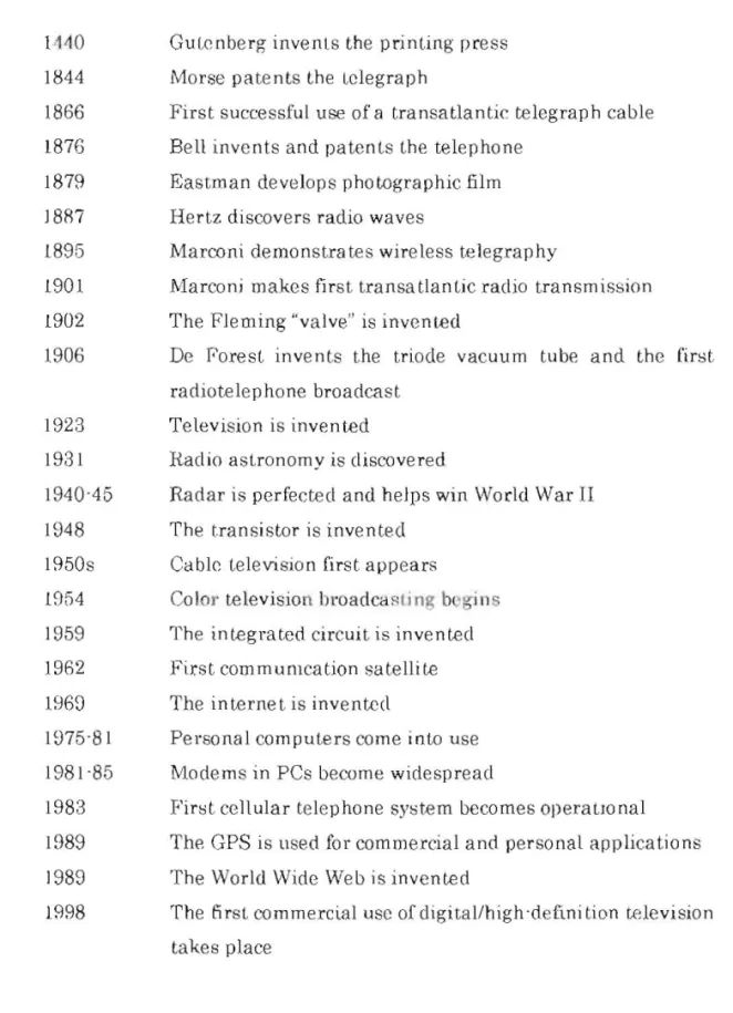
In the late nineteenth century. whenever the electricity was discovered, many applications were explored. The telegraph and t.he telephone were invented
in 1844 and 1876 respectively. Radio was invented in 1887. The sequence of the
electronic and human telecommunication milestone is as below:
1 ~40 Gu Lc nberg invents the printing press
1844 Morse pate nts the telegraph
1866 First successful use of a transatlantic telegraph cable 1876 Bell inve nts and patents the telep hone
1879 Eastman develops photographic film
18R7 Hertz discovers radio waves
1895 Marconi demonstrates wireless telegraphy
1901 Marco ni makes first tra nsa tlantic radio transmission 1902 The Fleming "valve" is invented
1906 De rarest invents the triode vacuum tube and the first
radiotelephone broadcast
1923 Television is invented
1931 Radio astronomy is discovered
1940"45 Radar is perfected a nd helps win World War II
1948 The t.ransistor is invented
1850s Cable television first appears
1954 Color television hroadcast; ng b,'gins
1959 The integrat.ed circuit. is invented
1962 First commumcation satellite
1969 The internet is inventecl
1975"8 I Personal compute rs come into use 1981 "85 Modems in PCs become widespread
1983 First cellular telephone system becomes operatIO nal
1989 The GPS is llsed for commercial and personal applications
1989 The World Wide Web is invented
1998 The 5 rst co m mercial usc of digital/high "deftni tion television takes place
Fig 1.1 Time line of milestone in human and electronic communication
After all. the new-era communication equipments have play it
major I'ole in order W increase people's ability
w
share mformation_ Forinstance, e-mail is one of the elements that could allow individuals with
PCs to communicate with others over networks at anywhere_
Through internet, any information that is required could be
obtained that is bl'ought
w
the user via the communication networks. Allinformation are at our fingertips and this change the buying habits and
methods as well as the way to get Information_
We won't know how OUf live will be if we don't have any knowledge
and information from around the world through electronic
com munication. It seems that this kind of communication is plaYI ng Its
major role in wday's life.
1.3 TilE 1·;LBMENTS OF A COMMUNICAT'ION SYS'rI';M
Human message Input (voice, code, Transmitter (Tx) Noise Communicati on channel or medium Receiver (Rx) Message for Human Communication
fig. 1.2 The basic elements of any communication system.
All electronic communication systems have the basic form as shown above
that consist of a transmitter. a communication channel or mecilum, and a
receiver. The input Information is mostly from human and t.his input is also
called as intelligence signal. The signal is being input.ted to the t.ransmitter
which then transmit the message over the communication channel. The receiver
will pick up the message and it will be relayed to another human. Noise is an
element that is applied to any interference that degrades the transmitted
information.
1.3. 1. Transmitter
A t.ransmitter is designed to convert the information into a signal h"
transmission over the communication medium and it might be a microphone up
to a microwave radio tran smitter.
1.3.2 Communication Channel
A medium for the electronic signal being sent from one place to another. It
may be as SImple as a paIr of wires that carry a voice signal from a microphone
to a headset. The communication medium may also be a fiber'optic cable.
In addition, the medium may be wireless or radio. Radio makes use of
electromagne tic spect.rum where signals are communicated from point to point by
converting them into electric and magnetic fields that. propagate readily over long
dista nces.
Although the medium suports the transmission ol'information, it also attenuates It At the receiver, the signal appear much lower in amplitude due to the degradation of signal. Considerable amplification of the signal, both at the transmitter and the receiver, is required for sucressful communication.
CHAPTER 2
TELEVISION TRANSMTSSION
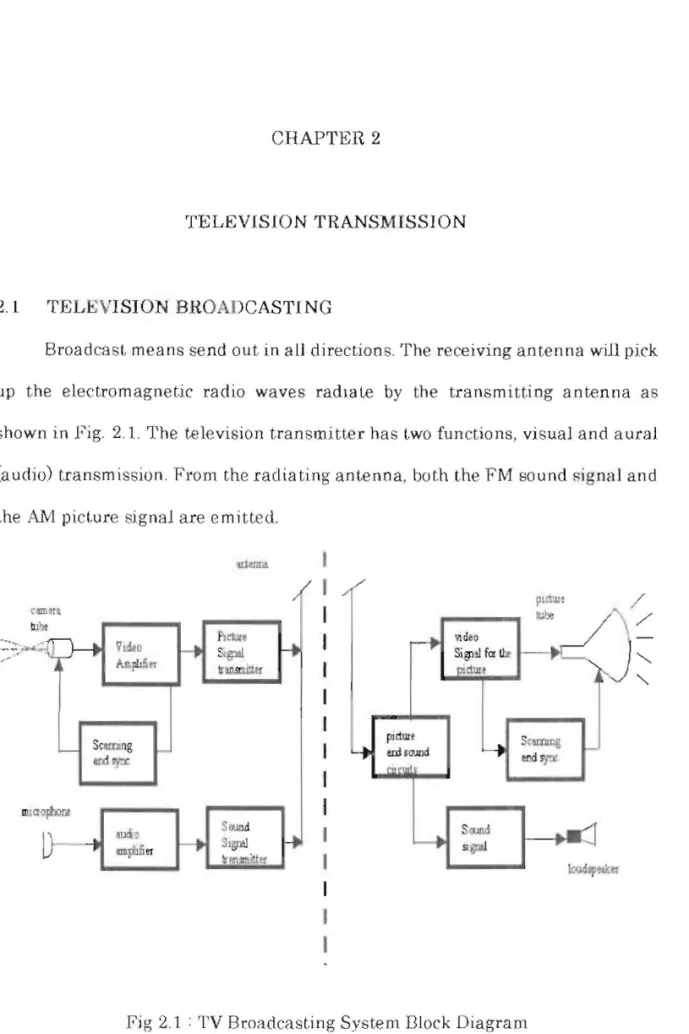
2.1 TELEVISION BROADCASTING
Broadcast means send out in all directions. The receiving antenna will pick
up the electromagnetic radio waves radiate by the transmitting antenna as shown in Fig. 2.1. The television transmitter has two functions, visual and aural
(audio) transmission. From the radiating antenna, both the FM sound signal and the AM picture signal are em i tted.
/ eo!lllltl
"',',
..
VI~O ..~
i--I
Sop!~
'.A~" ~ .o=nn Scunng L I wrpr IIIlaapixtr,t SOJOd ~l:Q1) s,~l}--
-1
..jl»HM
1
-1
~M'I~~~ / ' / , lit< /P'~
J
'
/
~cle()r+
Sitf1l1 for II:r,,<I»,
'~fv paiure u.d ,o.llldLJ
Y
~~""""'i
o:J! rpr4
S. Ollld pI.:r
1004 otk"Fig 2.1 • TV Broadcasting System Dlock Diagram
In visual transmission, the camera tube converts the light image to a video signal. The cathode ray tube (CRT) wit.h a photoelectric image plate and an
electron gun enclosed in a vacuum glass envelope is actually the camera tube.
The vidicon is a common type of camera. Basically the camera tube takes an
optical image of the scene on its photoelectric image plate, which is scanned in
horizontal lines by the electron beam. The scanning goes from left to right and
top to bottom, as viewed by the camera. The entire picture frame, comprising a total of 525 scanning lines takes 1130 s to scan. Hence, a sequence of electrical variations is the output of the camera tube which corresponds to the picture information (video signal).
The video signal is amplified, and synchroniSlOg pulses are added.
AmpliLLlde modulation of the picture carrier results in AM picture signal.
In color television, the syst.em use a color camera and a color pictUl'e tubp.
The video signals for the red, blue and green information are provided by the
color camera. Similarly, the image in green, red and blue, with all their color
mixtures including white are reproduce by the color picture tuhe.
For video and audio signal transmission, the band offrequencies used is called a
television channeL A GMHz wide channel with a specific carrier frequency is assigned to each television station by the Federal Communications Commission
Opposite polarity rcpresent thc video signal variations corresporld to
visual information, with black and white. Fig. 3.2 shows a video signal as a result of a black and white picture being scanned which is called as the luminance or
the Y signal. I 2 3 4 5 (B) 6 2 4 6
~
~
0
1
JII
I
{
~
~
1
0
(C) (D) Fig. 2.2(A) Scene to transmit (B) Scene on camera scree n
( C) Scene scanned sequentially (0) Resulting electrical signal
2.2 VlDE;O MODULATION
For the picture carrier signal. the 6MHz bandwidth is mai nly rleeded. The
vIdeo signal with a wide range of video frequencies up 1.0 approximately 4MHz modulate the amplitude of the carrier signa\. The highest video modulating
frequencies of 2 Lo <\ MHz l'Orrespond to the smallest horizontal details in the
picturc.
2.3 CHlW M1 NANCE MODULATION
The color mformation for broadcast in color is contain in the 3.58MfIz
chrominance signal. In order UJ form one video signal that modulates the picture carrier wave for transmission to the receiver, the color signal is combined with the luminance signaL C signal or the chroma signal is another name for the chrominance signal.
2.4 THE FM SOUND
Associated sound or the sound carrier signal for the picture also included in the 6 MHz channel. The audio frequencies which are in the range of 50 to 15000 Hz modulating the sound carrier. This audio frequency range is the same
8" that. for stalions in the commercial FM broadcast band of 88 to 108 !l111z. In the TV sound signal, the maximum frequency swing of the carfle!" J; :!. 25
kilohertz (kHz) for 100 percent modulation. This swing is less than the
±
75 kHzfor 100 perce nt modulation in t.he commercial FM broadcast band. The FM
sound syst.em has all the advantages compared with AM, including less noise and inte rference.
AM is better for the picture signal because the ghosts resulting from multipath reception are less obvious. By using t.he FM system, the ghosts will
flu lter compared to AM.