Date of publication: 30 October 2013
T
his article presents a novel robotic assistive device for the handling of large payloads. The design of the robot is based on the application of the following fundamental mechanical principles: inertia is mini-mized, a parallel closed-loop cable/belt routing sys-tem is used to kinematically decouple the transmission from fixed actuators and to the end-effector, and variable static bal-ancing is used to minimize the actuation forces required for vertical motion. As a result, the device requires only low power, thereby improving safety, and can be operated manu-ally, even in the event of a power failure (with minimum backup power for brake release). A novel force/torque sensor is also introduced along with a control algorithm based on vari-able admittance that provides a very intuitive interface forphysical human-robot cooperation. Finally, a full-scale proto-type integrating all of the above concepts is presented.
Designing a Safe Robotic Device
Human-robot cooperation is seen by many as one of the key challenges of 21st century robotics. To expand their applica-tions and the variety of services to humans, robots must somehow be integrated into human activities.
Over the last decade, several research initiatives have focused on the development of safe and intuitive robots for human-robot cooperation [1]–[3]. Several principles have been pro-posed to design intrinsically safe robots, such as the introduction of compliance in their actuated joints. The safety issue is even more critical when large and/or heavy payloads are to be han-dled. The latter situation is common in industrial tasks such as in automotive assembly lines, where some form of mechanical assistance is required to help human operators manipulate heavy Digital Object Identifier 10.1109/MRA.2013.2283651
A Friendly
Beast of Burden
A Friendly
Beast of Burden
By Clément Gosselin, Thierry Laliberté, Boris Mayer-St-Onge, Simon Foucault, Alexandre Lecours, Vincent Duchaine, Noémie Paradis, Dalong Gao, and Roland Menassa
A Human-Assistive Robot for Handling Large Payloads
payloads and avoid ergonomic stress. Robotic devices have been proposed in the past to perform such tasks, e.g. [4]. Although existing robotic devices can be used, provided that safety stan-dards are followed [5], it is desirable to improve the safety and intuitivity of present-day robotic assistants.
The current research work aims to develop an intrinsically safe robotic device capable of handling large payloads in an industrial setting. To this end, fundamental issues are addressed up front and a robotic prototype is introduced that includes several novel principles. The degrees of freedom (DoF) allowed by the robotic system presented in this article are the so-called group of Schonflies motions [also referred to as the Selective Compliance Assembly Robot Arm (SCARA)-type motions], i.e., displacements in all three directions ^XYZh
and rotations i around one direction. Here, rotations are assumed to take place about a vertical axis. SCARA-type motions are very common in assembly operations, thereby justifying their choice for the development of a prototype of a human augmentation robot.
The following issues are addressed in this article. First, the mechanical architecture is considered and a C-shaped end-effector structure is proposed to minimize the internal forces
and power. Kinematically decoupled transmission schemes with fixed actuators are also proposed, and static balancing is introduced as a means of drastically reducing the power of the robotic device. A novel force/torque sensor based on optical components is then proposed to significantly reduce the force signal noise and eliminate the drift, thereby improving control performance and intuitivity. Finally a con-trol algorithm based on variable admittance is introduced, and a prototype is presented.
Motion Range and Effectiveness: Mechanical Architecture
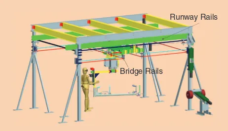
Minimizing the input power of a robotic device is one of the most effective means of improving safety. In the context of large payloads being handled by operators using assistive devices, accelerations are rather limited and, hence, the main external force involved in the handling of the payload is the support of its weight. Therefore, the weight support should be decoupled from the other actuation DoF and handled separately. This can be accomplished using the conventional bridge-and-trolley arrangement depicted in Figure 1, which was developed in this work. Moreover, the bridge-and-trolley architecture provides an effective way of producing large dis-placements while introducing limited additional inertia. It also provides a well-defined and well-shaped workspace.
In this architecture, a mast is moved in the horizontal direction (and rotated around a vertical axis). The up/down motion of the mast is decoupled from the other DoF, the lat-ter requiring only limited power. Moreover, to limit the inlat-ter- inter-nal forces in the bridge-and-trolley system, the center of mass of the payload should be roughly aligned with the supporting mast. To this end, a C-shaped end-effector is used here instead of a conventional L-shaped end-effector. In the C-shaped end-effector, the payload undergoes rotations around a vertical axis passing through its center of mass, which minimizes the rotational inertia (and thus the power of the actuator associated with this rotation). Additionally, because the payload’s weight is applied at the center of the trolley, the moments applied on the bridge are also mini-mized, which reduces the bending loads. The mass of the trol-ley components can therefore be reduced. The C-shaped end-effector is shown in Figure 2. The design also includes a variation of Elisha Otis’ elevator safety brake patented in 1861. In case of failure of the vertical supporting system, the end-effector is prevented from dropping.
Mechanical Innovation: Closed-Loop Cable/Belt Transmissions
In conventional bridge-and-trolley systems, actuators are mounted on moving components (bridge or trolley) and motion is produced with friction wheels rolling on the runway rails and on the bridge rails, as seen in [4]. Although this approach is conceptually simple, it requires that the actuators be mounted on moving links, including a powerful actuator needed for the vertical motion of the payload, which increases the moving mass and inertia.
Figure 1. A computer-aided design (CAD) model of the prototype of the intelligent assist device.
Runway Rails
Bridge Rails
Figure 2. A prototype of a C-shaped end effector. Emergency Brake Bearing
Linear Guide and Carriages
Cockpit Load Tool Control
Handle
A different approach is used here. The actuators are fixed to the ground structure, and cable/belt routings are used to drive the motion of the end-effector. Open-loop routings require that the cables be wound on winches and that at least one more actuator than DoF be used, leading to more com-plex control and winding issues. Closed-loop routings are therefore proposed here as a simpler and more effective alter-native. As explained in [6], a system with closed-loop routings requires only as many actuators as DoF. Also, the initial ten-sion in the closed cable/belt loops is independent from the control system and is established at the mounting by a mechanical tightening system. Closed-loop routings also have an advantage of eliminating the need for spools since the total length of each loop is constant, thereby alleviating the wind-ing issues. As a result, components other than cables, such as timing belts, can be used. Furthermore, as explained in [6], maintaining the transmission system fully decoupled provides several advantages, namely, minimization of the actuation power and minimization of the maximum end-effector forces. Therefore, the routings proposed here are designed accordingly. The transmission routings associated with each of the DoF of the assistive robotic device are now detailed. The routing corresponding to the vertical motion requires special attention because this motion involves the weight of the end-effector and payload. Therefore, vertical motion is treated in a separate section.
Displacement Along the Runway Rails
A fixed reference frame is defined with its X axis along the direction of the runway rails, its Y axis along the direction of the bridge rails, and its Z axis vertical. To avoid generating a residual torque on the bridge, the routing illustrated in Figure 3 and found in [7] and [8] is used here to produce motion along the runway rails. The cable/belt loop drives the bridge via two points, which provides stability.
Displacement Along the Bridge Rails
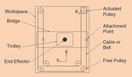
The routing used for the displacement along the bridge rails can be found in [7]–[10] and is illustrated schematically in Figure 4(a). It is pointed out that this routing is independent from the position of the bridge in the X direction. This is pos-sible because of the two free pulleys on the Y displacement trolley. The routing does not apply any torque on the bridge to maintain its tension and when it is actuated.
Rotation Around a Vertical Axis
A cable routing allowing a fully decoupled rotation, i.e., a rota-tion decoupled from the X and Y motions, is proposed. This routing is illustrated schematically in Figure 4(b). First, a trans-lation is produced on the end-effector, which is then converted into a rotation by a rack and pinion or an equivalent mecha-nism. This routing does not induce any torque on the bridge to maintain its tension, but it produces a torque when actuated. Indeed, different tensions occur along the cable/belt when it is actuated. Then, because of the routing configuration, the dif-ferent reaction forces applied on the pulleys attached to the
bridge result in a torque. This is an additional incentive to minimize the inertia through the use of a C-shaped end-effec-tor, as proposed earlier.
Alleviating Gravity: Vertical Actuation and Variable Static Balancing
Vertical Actuation
The transmission routing for the displacement along the verti-cal direction is different from that of the other axes since it is the only axis that involves gravity. Assuming accelerations con-siderably smaller than the gravitational acceleration, the forces and torques involved in this routing are significantly larger than in the other routings. Therefore, the transmission routing for the vertical motion should preserve the decoupling between the vertical motion and the other motions to separate routings with different magnitudes of forces. This routing is illustrated schematically in Figure 5 and is similar to the con-cept found in [10]. However, it is much more stable because it avoids applying a large torque on the bridge and rails system. It is easily observed from Figure 5 that horizontal motions have no effect on the loop driving the vertical motion and vice versa. Therefore, the vertical motion is completely and always decoupled from the horizontal motions. Since it is not a planar, the loop associated with the vertical motion is preferably built
Figure 3. The routing used for the displacement along the runway rails.
Y X Workspace
Bridge
Actuated Pulley Attachment Point
Free Pulley Cable or Belt
i
1
End Effector Trolley
Figure 4. The routing used for the (a) displacement along the bridge rails and (b) rotation around a vertical axis.
i
4
i
2
using a cable. Actuation can be provided by a pulley fixed to the ground that is feeding the cable (e.g., the pulley identified as i3 in Figure 5). However, in the prototype developed in this
work, the vertical motion is driven by a translation of the pul-ley that supports the counterweight with the help of a linear slider that includes a ball screw.
Static Balancing
Since the actuation of the vertical motion is completely decoupled from the other motions, it is the only DoF that requires large input forces. However, the large input forces are due to gravity, a predictable and consistent force that can be compensated by using static balancing. Static balancing has the advantage of drastically reducing the actuation forces and therefore significantly improving the safety of the robot. To this end, a counterweight has been included in the cable rout-ing, as illustrated in Figure 5.
Because of the decoupling feature of the routing proposed for the Z displacement, the counterweight only has to move along the vertical direction and does not add inertia along the other axes of motion. It is noted that a similar feature can be found in [11] but for the decoupling between the vertical motion and only one other axis of motion.
Variable Balancing Principle
The payload to be handled by the robotic device can be varied. For instance, the device can be loaded or unloaded. Therefore, the counterweight should be actively adjusted. To this end, the counterweight is mounted on a lever and an actuator is used to displace the counterweight along the lever. This lever is designed so that its angular motion is relatively small. Therefore, referring to Figure 6, static equilibrium requires that
, ,
FdL M gdL L M gd dC C C M dM
C L L
= = = (1)
where F is the balancing force (which corresponds to the mass of the load to be balanced, ML),MC is the mass of the counterweight, g is the gravitational acceleration, dL is the distance between the point of application of F and the fixed pivot ,O and dC is the variable distance between the center of mass of the counterweight MC and the fixed pivot .O
In the balancing system, the mass of the counterweight MC and the location of the force dL are fixed. Therefore, a varia-tion in ML can be compensated for by a change in dC, accord-ing to (1). Finally, the vertical actuation is included in the static balancing routing. An actuator and a ball screw are used to perform the vertical motion. However, as mentioned above, the forces required at the actuator are only a fraction of the weight of the end-effector and payload because the static weight is always compensated for by the counterweight.
Communicating the User’s Intentions: Force/ Torque Sensor Based on Photointerruptors
Context
The robotic system presented in this article aims at providing assistance to a human operator in a variety of ways.
In the interactive mode, the operator makes use of a sensing handle to apply forces to the device. The input forces are used to infer the intentions of the operator and provide a simultaneous intuitive control of the four DoF. Therefore, it is important that the sensing handle is able to provide a well-conditioned force/ torque signal with low noise and no significant drift.
As pointed out in [12], force/torque sensors based on strain gauges are sensitive to noise and drift and are not well-suited for applications in haptics. Instead, optical compo-nents can be used in combination with compliant mecha-nisms. In this work, a 4-DoF force/torque sensor based on photointerrupters (PIs) was developed by combining single-axis compliant mechanisms.
Single-Axis Force Sensor
Each single-axis sensor, illustrated schematically in Figure 7, uses a compliant mechanism to convert the applied force into a linear displacement. This displacement is then measured through the gradual interruption of the light beam of a PI, which is an optical sensor composed of an infrared emitter and a phototransistor placed face to face. PIs have many advantages such as noncontact displacement measurement, very low noise sensitivity, minimal drift, and low cost. The compliant
Figure 5. The balancing routing that does not apply a torque on the bridge.
i
3
X Y Z
Figure 6. The principle of the balancing system.
dC
MC g dL
F
mechanism is a parallelogram composed of stainless steel spring leafs built using an electrical-discharge machine. For redun-dancy, two PIs are attached to the compliant mechanism. The compliant mechanism has the advantage of being very compli-ant along the measured direction compared to the compliance along the other directions, which leads to a decoupled behavior of the 4-DoF assembly. To protect the flexures from any poten-tial overload along the sensor axis, inner mechanical stops are included. Also, to finely adjust the position of the PIs, the latter are installed on a mobile bar. This mobile part is installed on compliant rings and pulled by screws, allowing for fine adjust-ment of the position using two adjustadjust-ment screws.
Sensor Assembly
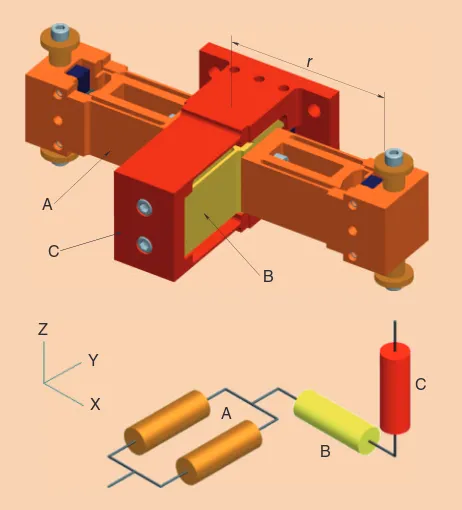
To measure the applied forces, the sensing handle combines a minimal number of four single-axis force sensors, mounted as shown in Figure 8. The mechanical assembly is composed of a pair of sensors mounted in parallel (A) combined with two other sensors mounted in series (B and C), as illustrated on the simplified schematic of Figure 8, in which the compliant axis of each sensor is represented by a prismatic joint. While the single-axis sensors (B) and (C) each measure one force acting along their respective axis (FxandFz and respectively), the pair of sensors mounted in parallel (A) acts as a bar pivoting about its center, allowing a torque measurement as well as a force measurement. This serial assembly of three components forms the link between the manipulated part of the handle and its fixed part. In other words, the handle is attached to the pair of sensors (A) by two rotational joints, while the last single-axis sensor (C) is rigidly attached to the base of the handle.
Sensing Handle
To provide safe and intuitive control of the assistive device, the handle is mounted on the exterior vertical beam of the C-shaped effector, at a safe distance from the payload. The handle dimensions have been chosen to satisfy the ergonomic standards specified in [13]. Finally, two pairs of through beam photoelectric sensors are added to the handle to detect the presence of the operator’s hands on each side of the handle, as prescribed by safety norms for hands-on control mode [5]. The sensing handle is shown in Figure 2, where it is referred to as the control handle.
For comparison purposes, an example of the force signal obtained from the sensing handle proposed here is plotted in Figure 9 together with a signal obtained from a commercial six-axis force/torque sensor based on strain gauges. It can be observed that the noise is considerably lower with the force/ torque sensor based on PIs. It was also verified experimen-tally that the drift is significantly reduced with the sensing handle based on PIs, when compared with the sensor based on strain gauges.
Intuitive Interaction: Inference and Control Algorithms
Three motion modes are considered here, namely
autono-mous mode, interactive mode, and passive mode. In
autonomous mode, the robot moves by itself, for instance, to fetch a part and present it to the operator. In interactive mode, the operator guides the motion of the robot using the sensing handle. Finally, in passive mode, the robot is powered off and the operator is moving the end-effector. This mode can be used in case of a failure of the controller or actuators.
In autonomous mode, the robot is controlled using a con-ventional proportional integral derivative controller, which is not discussed in this article. In interactive mode, a control scheme based on admittance control is implemented. Admittance control accepts a force as a measured input and produces a displacement (see [14] and [15]). This is in con-trast with impedance control, which accepts a displacement as a measured input and produces a force. Impedance control
Figure 7. A schematic representation of one of the single-axis force sensors.
Adjustment Screw PI
Mobile Bar Spring Leafs
Mechanical Stop
Figure 8. A CAD model and schematic representation of the assembled housings of the sensing handle.
r
A
Z
A C
C B
B Y
represents the vast majority of applications in haptics litera-ture, while admittance control is less commonly used. However, impedance control is most appropriate for devices with low inertia and friction since the user will inevitably feel these forces.
Because the manipulation of large and heavy payloads is considered here, large inertia and friction forces are expected, making an impedance controller inappropriate. On the other hand, an admittance controller is well suited for such applica-tions and, hence, the latter is used here. The one-dimensional admittance equation is written as [14]
( ) ( ) ( ),
fH=m x
p
-xp
0 +c xo
-xo
0 +k x-x0 (2)where fH is the interaction force, i.e., the force applied by the human operator, m is the virtual mass, c is the virtual damp-ing, k is the virtual stiffness, x0 is the equilibrium point, and
, , and
x x
o
xp
are respectively the position, velocity and acceler-ation. The virtual parameters (mass, damping, and stiffness) correspond to the prescribed behavior perceived by the user. Since it is desired to simulate free motion, the stiffness, k, as well as the desired position, ,x0 the desired velocity, xo
0, andthe desired acceleration, x
p
0, are set to zero. The admittanceequation is then rewritten as
.
fH=mx
p
+cxo
(3)The trajectory to be followed by the robot can be prescribed as a desired position, ,xd or as a desired velocity, x
o
d. For velocity control, the desired velocity can be written, in the Laplace domain, as Velocity control is used here, similarly to what was presented in [16]–[18]. Indeed, with position control, the robot would be attracted to a given reference position, which does not rep-resent the desired behavior. A discretized desired velocity is obtained with a zero-order-hold (a bilinear discretization could also be used) and is represented by( ) ( ) ( ) ( ), the desired velocity, and Ts is the sampling period. The desired acceleration at time step ,k noted x k
p
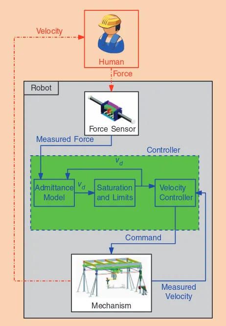
d( ), is thenrepre-Figure 10 presents the control scheme used in this work where a proportional controller is used as the velocity con-troller. No derivative gain is used to improve robustness (the acceleration signal is typically noisy), and no integral gain is used because the behavior to an operator input would then depend on the error history and would be counterintuitive.
Figure 9. The force signal obtained with the proposed sensor and a commercial force/torque sensor.
Figure 10. The control scheme using a velocity controller.
The transfer function between the input force and the out-put velocity corresponds to that of a first-order system, given in (4), where the parameters are the virtual mass ^ hm and the
With the transfer function ( ),H s it becomes apparent that the virtual damping affects the steady state value of the response while the ratio of the virtual mass over the virtual damping affects the dynamics (it changes the pole of the first-order sys-tem). It is recognized in the literature that the damping param-eter has a greater influence on human perception than the vir-tual mass [16]. When the admittance parameters (virvir-tual mass and virtual damping) are set to high values, a larger force is generally required to move the robot at a given velocity and/or acceleration. However, it is easier to perform fine movements since the robot is less reactive and interaction is thus smoother. When the parameters are set to low values, it is then generally easy to move the robot at high velocity and/or acceleration but more difficult to perform fine movements. In summary, there is a compromise between the force required to move the robot and the ability to perform fine movements. This is the main drawback of a fixed admittance control. Therefore, in this work, a variable admittance control approach is used. The objective of variable admittance control is to adjust the admit-tance parameters according to the inferred human intentions. In other words, high admittance parameters are desired when the operator performs fine movements, while lower values of the parameters should be used when movements involving large accelerations are performed.
The approach used here is presented in more detail in [19]. First, the intentions of the operator are inferred by computing the desired acceleration using (6) and by applying the scheme shown in Figure 11. Admittance parameters are then adjusted accordingly, as explained in the following.
When acceleration is desired, both virtual damping and virtual mass should be decreased. Although several solutions are possible, here the virtual mass to virtual damping ratio is kept constant, i.e., maintained at the default values. The vir-tual mass to virvir-tual damping ratio being constant, the dynam-ics of the device will remain similar [see (7)], which is more intuitive for the operator.
When a deceleration is desired, ideally, the damping should be increased while the mass is decreased. To produce this behavior while maintaining continuity of the parameters, an exponential function is used to compute the virtual mass. With this approach, the designer can choose a minimum vir-tual mass to virvir-tual damping ratio and set a transition smoothness parameter.
Equations for the variable damping and variable mass are heuristically chosen as where mv is the effective virtual mass, cv is the effective vir-tual damping, mf is the default virtual mass, cf is the default virtual damping, b^0< b< 1h is a parameter used to adjust the steady state virtual mass to virtual damping ratio, c is a parameter used to adjust the smoothness with which the ratio changes, and aa and ad are parameters to be tuned. In practice, for a given maximum magnitude of ,x
p
d denoted, xdmax
e
p
e a rough estimate of aa and ad can be obtained byFigure 12. The end-effector of the prototype of the 4-DoF robotic assistive device.
Figure 11. The scheme used to infer human intentions.
preventing cv from reaching the minimum, cmin, or
maxi-mum, cmax, allowed damping
. x
c c
x
c c
max min
max max
a d f
d d
f e e
e e
.
. a
a
-p
p (10)
Performance Demonstration: Prototype Development and Experiments
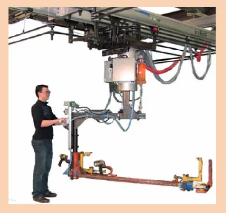
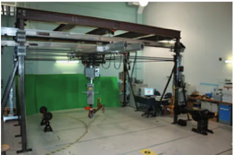
A prototype of the 4-DoF robotic assistive device proposed in this article was built at Laval University as part of a collabora-tive research initiacollabora-tive between the Laval University Robotics Laboratory and the General Motors Global Research Centre. The prototype includes all the innovations presented in the previous sections, namely the closed-loop transmission rout-ings, the variable static balancing principle, the sensing handle based on PIs, and the novel control algorithms. It was devel-oped in the context of assembly line assistance for the automo-tive industry. Photos of the prototype are shown in Figures 12 and 13. The prototype has a payload capability of 113 kg, a workspace of . (L)3 3 #2 15. (W)#0 52. (H) m, and a rota-tional range of motion of 120˚ about the vertical axis.
Mechanical Implementation
The closed-loop mechanical transmissions are implemented using timing belts for all DoF except for the vertical motion,
which uses a cable. All closed loops are driven using brushless servo actuators mounted on the fixed frame. Most mechanical components are composed of steel.
The fourth DoF (vertical motion) uses the routing presented in Figure 5 for static balancing. A steel cable is used for the ver-tical motion because of the large forces involved. The balancing is implemented using a pivot and lever with a counterweight that can be moved along the lever, according to the principle explained in Figure 6. The balancing system can be seen on the right-hand side of the prototype in Figures 1 and 13.
Controller Hardware
The controller of the assistive robotic device was built following a proven configuration used in industrial robotics. In this con-figuration, a personal computer (PC) is used as a central unit while a programmable logic controller (PLC) is used to moni-tor all components (including the PC) and deal with safety/reli-ability. One of the advantages of this configuration is to separate the software part of the controller from the hardware.
The hardware is composed of off-the-shelf components, namely a dual-core 3-GHz PC, a Sensoray 626 acquisition card, and an Allen-Bradley MicroLogix 1769 PLC. The actua-tors are controlled using Copley Xenus XTL-230-40 drives. Path planning algorithms and torque calculations are exe-cuted by the PC.
Simulink and RT-Lab are used to program the control algorithms. The PC/PLC combination together with RT-Lab leads to a stable, robust and yet flexible controller, running at a servo rate of 500 Hz.
Performance
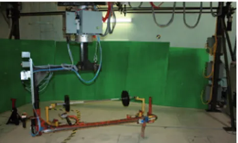
Videos demonstrating the features and the effectiveness of the prototype can be found at: http://robot.gmc.ulaval.ca/en/ research/theme507.html. Photos taken during the experi-ments are also shown in Figures 14 and 15. Among other experiments, a drawing task was used to test the dexterity and fine motion control of the prototype (see Figure 14). The drawing task consisted of starting from a given point, advanc-ing for 1.5 m, avoidadvanc-ing an obstacle by turnadvanc-ing 90˚, advancadvanc-ing 1.25 m, and then moving to the drawing board by performing a 1-m lateral displacement. Finally, the operator had to follow a maze while tracing the path on a piece of paper with a pen mounted on the robot at 1.4 m from the handle. The perfor-mances obtained with this task [19] are a clear demonstration of the control capabilities.
Other experiments involved the lifting and manipulation of heavy payloads of up to 100 kg. Barbells were used to emulate the payloads, as shown in Figure 15. During such typical coop-eration tasks, the average power used by the robot is approxi-mately 390 W. This low power resulted due to static balancing. In addition to providing safety, static balancing allows the pay-load to be handled manually in all DoF even in the occurrence of a failure (passive mode of motion). In the latter mode, dem-onstrated in the videos, the brakes are released and the mecha-nism is moved manually. Although not ergonomically sustain-able, this mode of operation is very important because it
Figure 13. A prototype of the 4-DoF robotic assistive device. (Photo courtesy of the Laval University Robotics Laboratory.)
provides the ability to manually remove the robot from a given continuous operation (an assembly line) in case of failure.
Conclusion
This article presents the design and control of a novel 4-DoF assistive robot for the handling of large payloads. In this design, the actuators are fixed and a set of decoupled cable/belt closed-loop routings are used to produce the motion of the end-effector. Additionally, static balancing is used to drastically reduce actuator power and torque. A novel force/torque sensor is also integrated in the robot, and control algorithms based on variable admittance are used. A full-scale prototype integrating all of the above concepts was built and tested. The low-inertia and low-power design combined with drift-free and low-noise force/torque measurements as well as effective control algo-rithms lead to a very intuitive physical human-robot interac-tion, as shown in the supporting videos.
Acknowledgments
The authors would like to acknowledge the financial support of the Natural Sciences and Engineering Research Council of Canada (NSERC, Grant RDCPJ 334898) and of General Motors of Canada.
References
[1] M. Zinn, B. Roth, O. Khatib, and J. K. Salisbury. (2004). A new actuation approach for human friendly robot design. Int. J. Robot. Res. [Online]. 23(4–5), pp. 379–398. Available: http://ijr.sagepub.com/content/23/4-5/379.abstract [2] R. Schraft, C. Meyer, C. Parlitz, and E. Helms, “Powermate—A safe and intuitive robot assistant for handling and assembly tasks,” in Proc. IEEE Int. Conf. Robotics Automation, Apr. 2005, pp. 4074–4079.
[3] A. Albu-Schäffer, S. Haddadin, C. Ott, A. Stemmer, T. Wimböck, and G. Hirzinger, “The DLR lightweight robot: Design and control concepts for robots in human environments,” Ind. Robot: Int. J., vol. 34, no. 5, pp. 376–385, 2007. [4] J. E. Colgate, M. Peshkin, and S. H. Klostermeyer, “Intelligent assist devices in industrial applications: A review,” in Proc. IEEE/RSJ Int. Conf. Intelligent Robots Systems, 2003, pp. 2516–2521.
[5] Robotic Industries Association, “BSR/T15.1 draft standard for trial use for intelligent assist devices—Personnel safety requirements,” Robot. Ind. Assoc., pp. 1–45, Mar. 2002.
[6] T. Laliberté, C. Gosselin, and D. Gao, “Closed-loop actuation routings for cartesian SCARA-type manipulators,” presented at the ASME Int. Design
Engineering Technical Conf. Computers Information Engineering, Aug. 2010. Paper DETC2010-28718.
[7] D. P. Rogers and D. J. Geisel, “High speed, low mass, movable probe and/or instrument positioner, tool and like items suitable for use in a controlled envi-ronment chamber,” U.S. Patent 4 527 119, July 2, 1985.
[8] J. Muller, M. Hoppe, and W. Jager, “Motion-transmitting arrangement,” U.S. Patent 3 611 819, Oct. 12, 1971.
[9] N. I. Levy, “Carriage positioning system,” U.S. Patent 4 524 520, June 25, 1985. [10] A. J. Lawler, “Machine drive system,” U.S. Patent 4 922 173, May 1, 1990. [11] R. W. Hannen and N. P. Vermeulen, “Palletizing apparatus,” U.S. Patent 5 425 464, June 20, 1995.
[12] S. Hirose and K. Yoneda, “Development of optical six-axial force sensor and its signal calibration considering nonlinear interference,” in Proc. IEEE Int. Conf. Robotics Automation, May 1990, vol. 1, pp. 46–53.
[13] “Ergonomics engineering/vendor guidelines for assists and specialized tools,” GMVO Ergono., p. 1–3, June 2005.
[14] L. Villani and J. De Schutter, “Force control,” in Handbook of Robotics, B. Siciliano and O. Khatib, Eds. Berlin: Springer-Verlag, 2008, ch. 7, pp. 161–185. [15] R. van der Linde and P. Lammertse, “HapticMaster—A generic force controlled robot for human interaction,” Ind. Robot Int. J., vol. 30, no. 6, pp. 515–524, 2003. [16] V. Duchaine and C. Gosselin, “General model of human-robot coopera-tion using a novel velocity based variable impedance control,” in Proc. World Haptics, Mar. 2007, pp. 446–451.
[17] T. Tsumugiwa, R. Yokogawa, and K. Hara, “Variable impedance control based on estimation of human arm stiffness for human-robot cooperative calligraphic task,” in Proc. IEEE Int. Conf. Robotics Automation, 2002, vol. 1, pp. 644–650. [18] R. Ikeura and H. Inooka, “Variable impedance control of a robot for coop-eration with a human,” in Proc. IEEE Int. Conf. Robotics Automation, 1995, vol. 3, pp. 3097–3102.
[19] A. Lecours, B. Mayer-St-Onge, and C. Gosselin, “Variable admittance control of a four-degree-of-freedom intelligent assist device,” in Proc. IEEE Int. Conf. Robotics Automation, May 14–18 2012, pp. 3903–3908.
Clément Gosselin, Department of Mechanical Engineering, Université Laval, Québec, Canada. E-mail: gosselin@gmc. ulaval.ca.
Thierry Laliberté, Department of Mechanical Engineering, Université Laval, Québec, Canada. E-mail: thierry@gmc. ulaval.ca.
Boris Mayer-St-Onge, Department of Mechanical Engineering, Université Laval, Québec, Canada. E-mail: [email protected]. Simon Foucault, Department of Mechanical Engineering, Université Laval, Québec, Canada. E-mail: foucault@gmc. ulaval.ca.
Alexandre Lecours, Department of Mechanical Engineering, Université Laval, Québec, Canada. E-mail: alexandre. [email protected].
Vincent Duchaine, Department of Mechanical Engineering, Université Laval, Québec, Canada. E-mail: vincent.duchaine@ etsmtl.ca.
Noémie Paradis, Department of Mechanical Engineering, Université Laval, Québec, Canada. E-mail: noemie.paradis.1@ ulaval.ca.
Dalong Gao, GM Global Research, Warren, Michigan, USA. E-mail: [email protected].
Roland Menassa, GM Global Research, Warren, Michigan, USA. E-mail: [email protected].