Manuscript received August 5th, 2012, revised October 1st, 2012 Copyright ©2012 Department of Industrial Engineering. All rights reserved.
CAD/CAM/CAE
Design Optimization of Multi Vacuum Manifold for Semiconductor
Industry
Taufik, R.S.*, Tan, S.T., Hambali, A., Tajul, A.A and Sivarao
Faculty of Manufacturing Engineering, Universiti Teknikal Malaysia Melaka, Durian Tunggal, 76100 Melaka, Malaysia
*Corresponding Author: [email protected] +60 6 3316899
Abstract
– This paper presents the design optimization of multi vacuum manifold in gripping system forsemiconductor industry. The objectives of this study were to investigate the parameter of designing manifold in vacuum system and analyze the results base on simulation software. The study was focused on the air flow in manifold system. The pressure drop, type of flow involved, and improper design were the factors that influenced the flow efficiency in manifold system. The study of multi vacuum manifold was carried out the design parameters involved such as various sizes of inlet, number of inlet used and the distance between the inlets used. The simulation was performed using CAD software to present the dynamic pressure and mass flow rates. Based on the simulation result, the design with the total cross section area inlets is less or equal to out resulted better value of velocity and suction pressure distributed in each inlet. In addition, the longer distance travels by fluid from inlet to outlet affects the result obtained. In conclusion, the new design of multi vacuum manifold for semiconductor industry was proposed. Copyright © 2012 Department of industrial engineering. All rights reserved.
Keywords: Design, simulation, multi vacuum manifold
1 Introduction
It has increase the demand of semiconductor in output of electric and electronic sector to the market significantly. In 2007, the product of the electrical and electronic is the largest contributor to manufactured export with shared 58.9% [1]. The growth of semiconductor industry in industrial sector affects to development of automation technologies. These technologies are used in solving the problems of automated operation in machinery of assembly, handling, inserting the semiconductor products in order to increase the productivity in industries. Vacuum technology is the technology that is widely used in semiconductor industry for the purpose of handling and inserting electronic components.
There are many type of manifold are created by designer in for the use of drive and distribute the flow into each branch of the pipe network. In recently, there are many researchers are study on the parameters of the manifold in order to increase the efficiency of the flow in main and lateral pipes. There are various approaches and techniques have been described in vacuum manifold
system. The parameters design for two types of manifold such as end manifold and center manifold designs in the aspect of pressure distribution from the water pump to the lateral pipe [2]. Multi-port was used to present the cylindrical distribution manifold supplied with air from an upstream pipe whose internal diameter is identical to that of the manifold [3]. The combustion efficiency of the engine was performed by reducing the backpressure in the exhaust manifold [4]. Beside these researchers, there are many researchers still study on parameters of the manifold in one of the purpose of increasing the efficiency of flow.
Copyright ©2012 Department of Industrial Engineering. All rights reserved Industrial Engineering Journal Vol.1 No.1 (2012) 5-10 contoured manifold design [6], and centralized and
decentralized manifold design [7].
The current problem in industry is facing the utilization of multi vacuum manifold design, which occurs in the suction pad. The suction pad could not perform holding process all the items efficiently. There are various times taken to extract the air from the suction pad. Means the vacuum generated is not uniformly and the time taken is long until all the air is extracted.
In this study, design and analysis will be concerned on the study of multi vacuum manifold. The design aspect will be carry out in this study are the number of the inlets, diameter, and distances of inlets used in manifold design. For the analysis aspect, it will concern on velocity of flow and pressure distribution in vacuum manifold for various parameter design.
2 Materials and Method
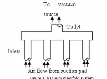
There are three parameters that will concern in this study, distance between inlets used in manifold system, number of inlets used, and the size between inlet and outlet to be considered. Figure 1 shows the type of manifold used in study of vacuum manifold.
Figure 1. Vacuum manifold system
Three designs were generated for vacuum manifold system. The Figure 2 shows the distances used in three manifold designs. The distance between inlets of manifold (a) are far away to each other compare to manifold (b), and the distance between inlets of manifold are close to each other (c). These designs were used to study the relationship between the distances with the pressure distribution in manifold.
Figure 2. Distance between inlets in various designs
The sizes of inlet used in manifold design have a great affect for air flow through vacuum manifold system. According to Figure 2, the diameter outlet of each
design will be set constant and the size inlets of design (c), (d) and (e) were set from bigger to smaller, where D2>D3>D4.
Figure 3. Number of inlets used in a same length of pipe.
Number of inlets used also one of the factors that will be used in design consideration in order to optimize the flow in manifold system. Figure 3 shows the various designs of numbers inlets used in this study. These designs were used to study on the efficiency of flow in manifold with different inlets used.
The manifold design which outlet is symmetric with the inlets will give uniformity result in pressure and velocity [4]. Therefore first model design created is shown in Figure 4 which contain with manifold block and 4 tubes with internal diameter of 7.5 mm. The diameter of outlet is 15 mm with the initial setup of 0.02 kg/s.
Figure 4. Multi-vacuum manifold with 4 inlets in (a) Isometric view, and (b) Cross section view
There are five groups of manifold parameters are developed and simulated with using SolidWorks, which are:
a) Number inlets of multi-vacuum manifold with constant diameter.
b) Size inlets with constant number of inlets.
c) Distance between inlets with constant number of inlets.
d) Multi-vacuum manifold with diameter base on A1=A2+A2.
e) Various sizes of inlets in a vacuum manifold.
Copyright ©2012 Department of Industrial Engineering. All rights reserved. Industrial Engineering Journal Vol.1 No.1 (2012) 5-10
3 Results and Discussion
3.1 Reference Design
The reference model of vacuum manifold was designed in the initial stage of design before further to study parameters. The manifold has a single outlet with 4 inlets and has the size of 15 mm diameter outlet and 7.5 mm diameter inlets. The size of inlets is referring to available size of tube on the market.
Figure 5. (a) Velocity flow at inside manifold, and (b) Pressure distribution at inside manifold
By referred to Figure 5, the flow trajectories shown at inlets have higher value of velocity and it is decrease before reach to manifold outlet. According to Bernoulli principle, the velocity of fluid will increase as the cross section area decreases, and the velocity will decrease as the cross section area increases. The velocity is decreased due to the cross section area of inlets are smaller than the cross section area inside manifold block, As shown in the Figure 5(a), the color of flow trajectories change from yellow to green and blue when went inside manifold block and the velocity increase again when close to the outlet. Based on the simulation result, the velocity in first inlet is 97.247 m/s and second and third inlet has higher velocity which is 104.577 m/s and 104.135 m/s. The inlets which were close to outlet have higher velocity and decreased as the distance become far from each other.
According to Figure 5(b), pressure distributed in second inlet and third inlet has low pressure (94995.82 Pa and 95047.11 Pa) compare to first and forth inlet which has pressure in 95824.36 Pa and 95859.23 Pa, respectively. It is found that the Bernoulli principle states an increase of fluid velocity occurs simultaneously on decreasing in pressure. Therefore, the pressure was affected by velocity generated. The low pressure occurs in second and third inlet is encouraging the fluid flow faster than other inlets.
For the mass flow rate, the first inlet and third have lower value compared to the inlet close to outlet. But the total mass flow rate of inlets boundary were equal to mass flow rate at outlet boundary, 0.02 kg/s. It is appeared that the result obtained is obeyed with conservation of mass principle. The main factor affect
the result of mass flow rate value is velocity of fluid pass through the inlets.
3.2 Number Inlets of Multi Vacuum Manifold with Constant Diameter
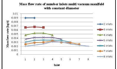
Figure 6 shows the chart of mass flow rate for the first study group. From the chart, 2 inlets vacuum manifold shows the highest value in mass flow rate in each inlet and follow by 3, 4, 5, 6, 7 and 8 inlets. As the number inlet increased, the mass flow rate is decreased simultaneously. Besides, the values of mass flow rate become inconsistence when the number inlets increased, which shown obviously in 8 inlets vacuum-manifold (0.002028, 0.002296, 0.002571, 0.003110, 0.003107, 0.002565, 0.002296 and 0.002027kg/s). All the designs were obey with mass conservation principle except 2 inlets vacuum manifold which the total inlet mass flow rate was 0.018kg/s compared to outlet mass flow rate value, 0.02kg/s. The velocity is the factor that affects the result in mass flow rate and pressure This phenomena can be explained by using mass flow rate equation, m=ρνA, which velocity of fluid is inversely proportionally to area. Therefore, when the number inlet of manifold is added from 2 to 3 and so on, the velocity is dropped because of the total cross section area is increased.
Figure 6. Mass flow rate of number inlets multi vacuum manifold with constant diameter
Copyright ©2012 Department of Industrial Engineering. All rights reserved Industrial Engineering Journal Vol.1 No.1 (2012) 5-10 Figure 7. Dynamic pressure distribution in vacuum manifold
3.3 Inlets with Constant Number of Inlets
Figure 8 show the mass flow rate for all 4 inlets manifold. From the chart, the mass flow rate distribution of each design have not significant different. The inlets diameter of 10 mm manifold shows the highest value of mass flow rate among the design in second study group, 5.55x10⁻³ kg/s while 6 mm diameter has the mass flow rate of 5.06x10⁻³kg/s.
Figure 8. Mass flow rate of 4 inlets manifolds with different sizes
Among these designs, the smaller size of inlets the mass flow rates has more consistent compared to manifold with large size. Simulation result showed that for 6 mm diameter inlets manifold, mass flow rate in first inlet was 0.00494 kg/s and follow by 0.00506, 0.00506 and 0.00494 kg/s. For 10 mm diameter inlets manifold, mass flow rate for first inlet was 0.00451 kg/s while second inlet was 0.0050 kg/s. It is shown that the larger size used will have greater value and sudden drop for the side inlets. The velocity is decreasing as sizes of inlet increasing. Increasing size mean the cross section area is increase simultaneously.
It is found that the suction pressure also drops when the size inlets increase from 6 mm diameter to 10 mm diameter. The suction pressure drops to 2144.96 Pa while the suction pressure of 6 mm diameter of 18775.36 Pa.
3.4 Distances between Inlets with Constant Number of Inlets
The mass flow rates in this group were similar for all manifold design, because the cross section areas were approximated uniform. There are slightly dropped in mass flow rate value when the distances between inlet increases as shown in Figure 9. Compare the values in third inlet, the mass flow rates are 0.003038, 0.003011, 0.002992, 0.003094kg/s respectively from 12 mm distances to 20 mm distances, the difference were very small and can be neglected.
Figure 9. Mass flow rate for different distances between vacuum manifold inlets
It is shown that the manifold with 20 mm distances between inlets has the highest value of suction pressure compare to other designs. The pressure distributed in the 20 mm distances shows the pressure of 1364.98, 1793.56, 2258.97 2689.66 Pa from first inlet to forth inlet. In addition, the manifold with 12 mm distances shows the value of 1412.71, 1861.12, 2101.2101.21 and 2311.23 Pa from first inlet to forth inlet.
3.5 Multi-Vacuum Manifold with Diameter Base on A1=A2+A2
By creating the designs using A1=A2+A2, the mass flow
Copyright ©2012 Department of Industrial Engineering. All rights reserved. Industrial Engineering Journal Vol.1 No.1 (2012) 5-10
Figure 10. Mass flow rate of multi inlets vacuum manifold
It is found that the velocity distributed in each inlet of multi vacuum manifold. The maximum velocity showed by 2 inlet were 116m/s and followed by 3 inlets to 8 inlets which have 106, 106, 112, 108, 111,121m/s respectively. All of these values were distributed in the range of 100 to 120 m/s. It is shown that the velocity inversely proportional to cross section area. Hence, the cross section area of the inlets to be constant and the result shows a very consistence value of velocity to each design. For the outlet manifold, the cross section area was 176.71 mm2. Table 1 shows the total cross section
area for all the inlets of different design in this study group. Since all the total area does not excess the value of 176.71 mm2, therefore the system can perform its has higher value of pressure in the range of 5000 Pa to 10000 Pa. The maximum value of 2 inlets vacuum manifold was 8145 Pa and followed by 3 inlets to 8 inlets which have the value of 6784P a, 6787 Pa, 7588 Pa, 7071 Pa, 7537 Pa and 8864 Pa, respectively. As the number inlets of manifold increased, the inlets which distributed far away from the outlet will have the lower pressure than close to center. The longer distance traveled by fluid makes the pressure drops due to viscosity of fluid and the different cross section area.
3.6 Sizes of Inlets in a Manifold
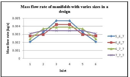
When using the different sizes in a design, the mass flow rate becomes inconsistence as shown in Figure 11. The designs with the same size for all inlets will have consistent and uniform. The mass flow rate for 7 mm diameter inlets were approximated similar except the first inlet and last inlet. When there were 2 sizes used, the mass flow rate suddenly dropped, particularly for small size. For the size 5 mm, 6 mm and 7 mm sizes used in a design, the larger size will have greater mass flow rate than the small size. In any case, the total mass flow
rate of inlet for all design equals to mass flow rate of outlet.
Figure 11. Mass flow rate of manifold with varies sizes
It is shown that the manifold with 1 size has the lowest velocity among the design models in this study group. For the design uses 2 sizes (2 of 6 mm and 4 of 7 mm diameters used), it is slightly increased for each inlet compared to preview design. It increases when 4 of 6 mm diameters were used. The design with 5 mm, 6 mm and 7 mm diameter shows the highest among the design. Since the velocity is inversely proportional, therefore the size of the design is decreased; it will increase the velocity simultaneously. But the values obtained were not consistence for all inlets of the design.
Table 2.Total cross section area
Group Mass flow rate Velocity Suction
pressure Overall consistency
inlets increases Better. 2 and 3 inlets Good
Size inlets,
distance increases Range of 12 to 18 mm distances have better
result Less
Multi-vacuum manifold, diameter based on A1=A2+A2
Drops as the
diameter increases All designs have better result than reference
design Good
Table 2 shows the best design parameters that can be accomplished. The total cross section area inlets were equal or less than total cross section area of outlet (to maintain value of velocity and pressure at high level). The better distances between inlets were in the range of 12-15 mm to reduce inconsistence occurring to inlets. Among the 5 groups of design parameter generated, the result showed that the vacuum manifold which designed in group 4 (multi-vacuum manifold with diameter base on A1=A2+A2), and 8 inlets vacuum manifold was the
Copyright ©2012 Department of Industrial Engineering. All rights reserved Industrial Engineering Journal Vol.1 No.1 (2012) 5-10
4 Conclusion
The design and simulation of multi vacuum manifold has been presented for the semiconductor industry. It is shown that the cross section area was the main factors that affecting final result such as suction pressure and velocity distributed. The distance was another factor that affects the result obtained at final stage. The velocity and pressures distributed to each inlet were maintained at high value if the cross section of inlets decreases as the number of total inlets increases. It is concluded that the better parameter to be considered in this study were total cross section area with the inlet was less or equal to cross section area, distance between inlets were in the range of 12 mm to 18 mm with the size in between 5 mm to7 mm diameter. Hence the design with 8 inlets, 7.5 mm diameter, and 15 mm distances between inlets showed the best design in this study.
Acknowledgements
This work was supported by the financial fellowship from the University Short Term Grant PJP/2011/FKP (14A) – S881, Universiti Teknikal Malaysia Melaka (UTeM).
References
[1] MGCC (Malaysian-German Chamber of Commerce), (2009). “Market watch electronics industry 2009.” Available at: http://malaysia.ahk.de/fileadmin/ahk_malaysia/Dokumente/Sek torreports/Market_Watch_2010/Petrochem_2010__ENG_.pdf. (Accessed: 13 September 2010)
[2] Schmidt, D.R., Janni, K.A., and Christopherson S.H. (2008). “Milk house wastewater design guide.” University of Minnesota Extension. Tavoularis, S. (2005). “Measurement in fluid mechanics.” US: Cambridge, pp. 208-220.
[3] Chen, A. and Sparrow, E. M. (2008). “Turbulence modeling for flow in a distribution manifold.” International journal of heat and mass transfer. vol. 52, pp.1573-1581.
[4] Gopal, P., Senthil Kumar, T. and Kumaragurubaran, B. (2009). “Analysis of flow through the exhaust manifold of a multi cylinder petrol engine for improved volumetric efficiency.” International Journal of Dynamics of Fluids. Vol. 5, no. 1 (2009), pp. 15–26. [5] Bannwarth, H. (2005). “Liquid ring vacuum pumps, compressors
and system: Conventional and hermetical design.” Germany: Wiley-VCH.
[6] Jimmy, T. C. K., Sparrow, E. M., and Abrahamb, J. P. (2009). “Geometric strategies for attainment of identical out flows through all of the exit ports of a distribution manifold in a manifold system.” Applied thermal engineering. Vol. 29, pp. 3552-3560.