Advanced Residual Coding
for MPEG Surround Encoder
Ikhwana Elfitri
∗, Muhammad Sobirin
†, Fadhlur Rahman
∗, and Rahmadi Kurnia
∗ ∗Department of Electrical Engineering, Faculty of Engineering, Andalas University,Kampus UNAND Limau Manih, Padang, 25163, Sumatera Barat, Indonesia †Department of Telecommunication Engineering, STT Telematika Telkom Purwokerto,
Jl. D. I. Panjaitan No. 128, Purwokerto, 53147, Jawa Tengah, Indonesia E-mail: [email protected]
Abstract—MPEG Surround (MPS) has been widely known as both efficient technique for encoding multi-channel audio signals and rich-features audio standard. However, the generation of residual signal in the basis of a single module in MPS encoder can be considered as not optimal to compensate for error due to down-mixing process. In this paper, an improved residual coding method is proposed in order to ensure the down-mixing error can be optimally minimised particularly for MPS operation at high bit-rates. The distortion introduced during MPS encoding and decoding processes is first studied which then motivates for developing an approach which is more accurate in determining residual signals for better compensation for the distortion. A subjective test demonstrates that the MPS with improved residual coding can be competitive to Advanced Audio Coding (AAC) multi-channel for encoding 5-channel audio signals at bit-rates of 256 and 320 kb/s.
I. INTRODUCTION
With the continuous development of high speed fixed and mobile Internet, high quality spatial audio [1] services are currently offered to end users in many applications such as news broadcasting and cinema industries. Among numerous key technologies taking part in the rise of delivering spatial audio services, compression and coding techniques [2], [3] are fundamental. Perceptual based parametric coding tech-niques, such as Parametric Stereo (PS) [4]–[6], Binaural Cue Coding (BCC) [7], [8], and MP3 Surround [9], [10], are considered as the most efficient approaches which led to a Moving Picture Expert Group (MPEG) standard, called MPEG Surround (MPS) [11], [12]. The MPS are basically developed based on a concept of Spatial Audio Coding (SAC) [13], [14] in which a number of audio channels are down-mixed and represented as lower number of audio channels, such as one (mono) and two (stereo). To be capable of recreating multi-channel audio signals, spatial parameters which include Channel Level Difference (CLD), Inter-Channel Coherence (ICC), and Channel Prediction Coefficient (CPC), must be extracted in the encoder and transmitted to decoder.
Major advantages of MPS can be discussed as follows. First, MPS benefits from reducing the number of audio channels with additional side information facilitating for more efficient encoding. For 5-channel audio signals, transmission is possible at a bit-rate as low as 64 kb/s. Second, the down-mixing of multiple audio signals offers an opportunity to employ
MPS as a coder that is backward compatible to any exist-ing mono or stereo audio coders, such as MPEG-1/2 layer 3 [15] and MPEG Advanced Audio Coding (AAC) [16], [17]. Third, MPS has a mechanism to compensate for error due to down-mixing process by transmitting residual signal, hence, waveform reconstruction of audio signals can be expected. Fourth, MPS also plays an important role in MPEG Spatial Audio Object Coding (SAOC) [18], [19] for transforming object-based metadata to channel-based parameters at the decoder side. Fifth, it is also possible to apply a closed-loop approach, called analysis-by-synthesis spatial audio coding [20]–[22], to minimise distortion caused by quantisation of spatial parameters leading to improvement in the quality of reproduced audio signals
Despite having numerous advantages, MPS still has at least one drawback. In MPS encoder, a residual signal is determined with the goal to compensate for error due to down-mixing of audio channels. However, the determining of residual signal is performed in a single elementary module [23], [24] while the whole structure of the encoder actually comprises of several modules causing the error compensation is not optimal for overall encoding process. In this paper we propose an im-proved method for residual coding in MPS encoder for better reconstruction of multi-channel audio signals. In contrary to the MPS standard where residual signal is determined in the basis of a single module, this improved method determines the residual signal based on the whole structure of multiple modules. Using this way, the residual signals compensate for error caused by not only the down-mixing of 2 audio channels inside a single module but also the structuring of multiple modules in a tree scheme, thereby minimising overall distor-tion in the encoding and decoding processes. This approach is particularly aimed at operating MPS at high bit-rates, such as 256 and 320 kb/s for encoding 5 channels of audio signals, when a perfect waveform reconstruction is expected.
II. OVERVIEW OFR-OTTANDOTT MODULES ONMPS
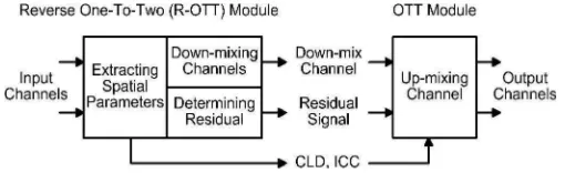
Fig. 1. Detailed schematic of R-OTT and OTT modules showing the processes of parameter extraction, down-mixing and generation of residual signal.
stereo audio channels into three channels. These modules can be employed in tandem to up-mix a mono or stereo audio channels into a higher number of audio channels. For instance, to re-create 5 audio channels from a single mono audio channel, 4 OTT modules can be used in a tree structure. For spatial analysis, the encoder can down-mix audio channels by employing a couple of reverse modules: Reverse-OTT (R-OTT) and Reverse-TTT (R-TTT).
Fig. 1 shows a detailed block diagram of R-OTT and OTT modules. At the encoder side, the R-OTT module carries out three processes: extracting Channel Level Difference (CLD) and Inter-Channel Coherence (ICC) as spatial parameters, down-mixing both input channels, and determining a residual signal, while at the decoder side the OTT module undertakes up-mixing process. Each process in the R-OTT and OTT modules is briefly discussed in the following subsection.
A. Extracting Spatial Parameters
The CLD and ICC, denoted as C andI, are calculated in an R-OTT module having two input signals x1[n], x2[n], as
follows:
C=
P
nx1[n]·x∗1[n]
P
nx2[n]·x∗2[n]
(1)
and,
I=
P
nx1[n]·x∗2[n]
pP
nx1[n]·x∗1[n]
P
nx2[n]·x∗2[n]
(2)
where nis the index of audio samples while the sign of (∗) represents a complex conjugate operation.
B. Down-mixing Channels
Down-mixing two audio signals in an R-OTT module is simply applied as the addition of both input channels as below:
y[n] = x1[n]
a+b+ x2[n]
a+b (3)
where y[n] is the down-mix signal. The a and b parameters are energy constants calculated based on the extracted CLD and ICC [24].
C. Determining the Residual Signal
Residual signal,r[n], is determined to compensate for error due to mixing process which can be found based on the following decomposition:
x1[n] =a·y[n] +r[n] (4a)
x2[n] =b·y[n]−r[n] (4b)
so that a single residual signal can be created for reconstructing bothx1[n] andx2[n].
D. Up-mixing Channel
At the decoder side, replica of both audio signals, ˆ
x1[n] andˆx2[n], are recreated in an OTT module from the
decoded down-mix signal, yˆ[n]. The up-mixing process is based on the estimated energy constants, ˆa and ˆb, and the decoded residual signals,rˆ[n], as follows:
ˆ
x1[n] = ˆa·yˆ[n] + ˆr[n] (5a)
ˆ
x2[n] = ˆb·yˆ[n]−rˆ[n] (5b)
where the estimated energy constants,aˆ andˆb, are calculated from the extracted values of CLD, C and ICC, I. Note that the quantisation of CLD and ICC as well as the encoding and decoding of down-mix and residual signals are not shown in the figure. Further details on the transformation of CLD and ICC into energy constants, as well as related spatial analysis and synthesis method in MPS, can be referred to [24].
III. IMPROVEDRESIDUALCODING
The method to determine residual signal in a single R-OTT module is capable of compensating for distortion caused by representing both input signals, x1[n] andx2[n], as only a
single down-mixed signal y[n]. However, this method is not intended to compensate for overall error when the encoder combines several R-OTT modules for down-mixing more than 2 audio signals. Employing a number of R-OTT modules in a tree structure causes the generated residual signal becomes an irrelevant compensation for the overall distortion introduced in the down-mixing processes. In this section we will analytically show this irrelevancy by comparing 3 encoding schemes of MPS [25] having different number of input: 2, 4, and 5 channels. Then, the proposed method for determining residual signals is discussed in details.
A. Distortion on MPS System
Let xc[n], xlf[n], xls[n], xrf[n], xrs[n] as 5-channel input signals for the center, left front, left surround, right front, and right surround channels, respectively, as shown in Fig. 2 within the tree structure of R-OTT modules. Based on (3), the 5-channel down-mix signal,y5ch[n], where the subscript of (5ch) shows the number of input channels, can be represented
as:
y5ch[n] =
xc[n]
aclr+bclr +
xlf[n]
(al+bl)(alr+blr)(aclr+bclr) +
xls[n]
(al+bl)(alr+blr)(aclr+bclr) +
xrf[n]
(ar+br)(alr+blr)(aclr+bclr) +
xrs[n]
(ar+br)(alr+blr)(aclr+bclr)
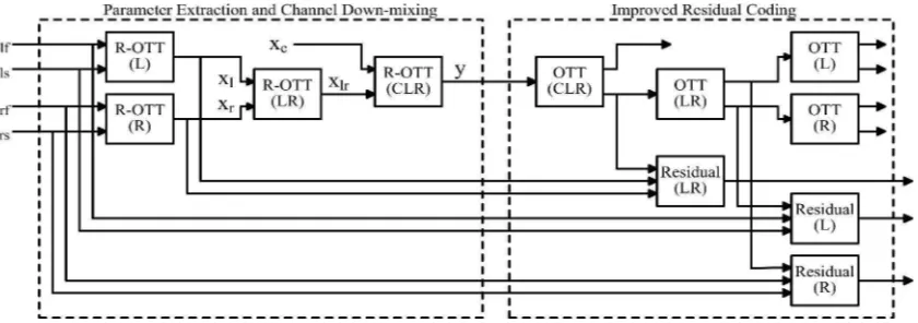
Fig. 2. Block diagram of the proposed improved residual coding in MPS encoder. Three new Residual modules: Residual(LR), Residual(L), and Residual(R); as well as four OTT modules: OTT(CLR), OTT(LR), OTT(L) and OTT(R) are required. Note that all OTT modules actually have similar structure as those applied in the decoder.
where aclr, bclr, al, bl, alr, blr, ar, br are energy constants de-rived from the extracted CLD and ICC on 4 corresponding R-OTT modules: (L), (R), (LR), and (CLR). Using (5), the reconstructed audio signal in the left front channel can be determined as below:
ˆ
xlf5ch[n] = ˆalˆalrˆaclr·yˆ5ch[n] + ˆalaˆlr·rˆclr(n)+ ˆ
al·ˆrlr(n) + ˆrl(n)
(7)
whereaˆl,ˆalr,ˆaclr are the estimated energy constants used in the corresponding OTT modules,yˆ5ch[n]is the decoded down-mix signal when having 5 input channels, andrˆclr,rˆlr,rˆl are the decoded residual signals applied to compensate for error in the particular OTT modules.
Using similar way the down-mix signal, having only 4 input channels applied by removing both R-OTT(CLR) and OTT(CLR) modules in Fig. 2, as well as the reconstructed audio signal in the left front channel can be found. The 4-channel down-mix signal, y4ch[n], can be written as:
y4ch[n] =
xlf[n] (al+bl)(alr+blr)
+ xls[n] (al+bl)(alr+blr)
+
xrf[n] (ar+br)(alr+blr)
+ xrs[n] (ar+br)(alr+blr)
(8)
while the reconstructed signal in the left front channel, ˆ
xlf4ch[n], can be stated as: ˆ
xlf4ch[n] = ˆalˆalr·yˆ4ch[n] + ˆal·rˆlr[n] + ˆrl[n] (9) where yˆ4ch[n] is the decoded down-mix signal when having only 4 input channels.
Furthermore, when only 2 channels become the input of the encoder consisting of the left front and the left surround employing R-OTT(L) and OTT(L) modules in the encoder and decoder, respectively, the 2-channel down-mix signal, ˆ
xlf2ch[n], can be derived as below:
y2ch[n] =
xlf[n] (al+bl)
+ xls[n] (al+bl)
(10)
and then the reproduced audio signal in the left front channel, ˆ
xlf2ch[n], can be written as: ˆ
xlf2ch[n] = ˆal·yˆ2ch[n] + ˆrl[n] (11) where yˆ2ch[n] is the decoded down-mix signal when having only 2 input channels.
It is shown in (7) that the reconstructed audio signal suffers from a variety of quantisation and coding errors introduced from: a down-mix signal, three components of residual signals, and three components of energy constants. In contrast, in (9) there is less error on quantisation and coding that affects the quality of the reconstructed audio signal. Furthermore, the reproduced audio signal in (11) relates on even less signals and parameters that contain quantisation and coding error. These indicate that employing more R-OTT modules in a tree structure will introduce more distortion. Understanding this phenomenon suggests us that applying residual coding in the basis of a single R-OTT module is not optimum to compensate for mixing distortion. Then, it motivates for employing residual coding in the whole structure of the tree scheme to compensate for all possible distortions.
B. Method to Minimise Distortion
The proposed improved residual coding, applied in MPS encoder for encoding 5-channel audio signals, is illustrated in Fig. 2. As many as 4 R-OTT modules are combined as a standard tree structure where both spatial parameter extraction and channel down-mixing are applied as specified in the stan-dard. For the proposed improved residual signal generation, 4 OTT modules, structured as identical to that applied at the decoder side, are embedded in order to re-create multi-channel signals which are assumed to be similar to those reconstructed in the decoder. Additionally, 3 new modules, called Residual module, are included in the scheme. For clarity, the standard tree structure and the proposed improved residual coding are separately marked in the figure with dashed lines.
signal is minimised. According to (5) the reconstructed signals of the left front and left surround channels can be stated as:
ˆ
xlf[n] = ˆal·xˆl[n] + ˆrl[n] (12a)
ˆ
xls[n] = ˆbl·xˆl[n]−ˆrl[n] (12b)
If perfect waveform reconstruction is expected then we as-sumed that we can replace both the reconstructed left front and left surround in (12) with the original signals i.e.xˆlf[n] =
xlf[n]andxˆls[n] =xls[n]. Due to the simple and linear form of equation (5), new residual signal can be approximated as:
rl,new[n] =xlf[n]−ˆal·xˆl[n] = ˆbl·ˆxl[n]−xls[n] (13)
Our experiments have shown that the first and second parts of (13) are identical ensuring that the proposed structure can provide a single residual signal, rl,new[n] to compensate for both of reconstructed signals, xˆlf[n] andxˆls[n].
This improved residual signal differs from the standard residual signal as below:
rl[n] =xlf[n]−al·xl[n] =bl·xl[n]−xls[n] (14)
Comparing both the improved and standard residual signals, it indicates that the improved residual signal has compensated for: first, the distortion introduced in both estimated energy constants,ˆal,ˆbl; second, the difference between a down-mixed signal from the R-OTT (L) module,xl[n], and a reconstructed signal, xˆl[n], which is expected to be the synthesized form of
xl[n].
Following the same way we can calculate the other residual signals as follows:
rr,new[n] =xrf[n]−ˆar·xˆr[n] = ˆbr·xˆr[n]−xrs[n] (15)
rlr,new[n] =xl[n]−ˆalr·xˆlr[n] = ˆblr·xˆlr[n]−xr[n] (16)
Considering the tree structure, the residual signal generated from the R-OTT(CLR) is just kept as it was without any improvement. The proposed improved residual coding is be-lieved to be applicable to other schemes such as for more number of input channels where more modules are involved or for different scheme of R-OTT structure. Moreover, when stereo down-mix is transmitted instead of mono down-mix, the proposed approach can also be applied to R-TTT module for generating improved residual signal.
IV. RESULTS
Five different 5-channel audio signals with duration of 12 s, consisting of: speeches, classical and acoustical music, as well as sounds of people laughing and clapping hands, were used as audio input in the experiments. They were selectively chosen from a large number long-duration audio signals and considered as critical materials for the encoding process due to a higher possibility of having transient events. A subjective test based on ITU-R BS.1116-1 [26] has been done to evaluate MPS (employing the proposed residual coding) at 2 total bit-rates: 256 and 320 kb/s, which are the typical bit-rates to operate AAC multi-channel for encoding 5.1 audio signals. The OTT modules inside the MPS encoder are applied as
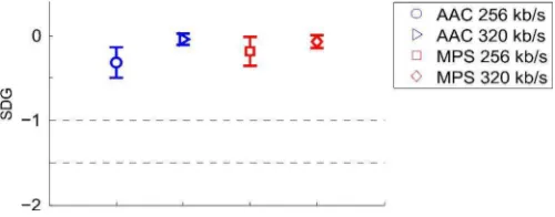
Fig. 3. Results of subjective test, comparing MPS (using improved residual coding) and AAC Multichannel, showing that the MPS can be competitive, in terms of Subjective Difference Grade (SDG), at both bit-rates of 256 and 320 kb/s.
shown in Fig. 2 where the LFE channel was removed for simplicity. The mono down-mixed signal was preferable to be transmitted instead of stereo down-mix in order to achieve a higher coding efficiency. For each operating bit-rates of 256 and 320 kb/s, MPS allocated 128 and 160 kb/s, respectively, for encoding the mono down-mix signal using AAC. The MPS operated with 20 parameter bands which means as many as 30 kb/s are required for transmitting the spatial parameters while the rest of the total bit-rate is uniformly distributed among all residual signals. For comparison AAC multi-channel was included in the listening test. For encoding both mono down-mix signal of MPS and multi-channel signal as benchmarking, Nero AAC codec were used.
As many as 20 listeners, who had experiences in the previ-ous subjective test based on ITU-R BS.1116-1, participated in the listening test. Post-screening has been applied to ignore invalid Subjective Difference Grade (SDG) scores from 6 subjects, i.e. subject with positive average SDG score, thus only the scores from the remaining 14 subjects were presented as results as given in Fig. 3. Average SDG score in the range of 3 grades: 0 (imperceptible), -1 (perceptible but not annoying), -2 (slightly annoying), is plotted with 95 percent confidence interval.
V. CONCLUSION
This paper has presented an improved method to generate residual signal in MPEG Surround (MPS) encoder. Instead of compensating for error in a single Reverse One-To-Two (R-OTT) module, the improved residual signal is expected to compensate for error in the whole tree structure of the combined R-OTT modules. Subjective test has demonstrated that MPS using the proposed method can be competitive to Advanced Audio Coding (AAC) multi-channel for encoding 5-channel audio signals at typical AAC operating bit-rates of 256 and 320 kb/s. Considering its advantages, such as backward compatibility to existing mono or stereo codec, bin-aural rendering feature, and bit-rate scalability, implementing MPS becomes much more compelling when it can achieve comparable performance to AAC multi-channel at higher bit-rates.
ACKNOWLEDGMENT
This work was funded by the Ministry of Research, Tech-nology and Higher Education, the Republic of Indonesia under the scheme of Higher Education Excellent Research (Penelitian Unggulan Perguruan Tinggi) with contract no. 50/UN.16/UPT/LPPM/2015. The authors would like to thank the reviewers for their constructive comments and suggestions to improve the quality of the manuscript. Furthermore, the authors also thank Mr. Heru Dibyo Laksono and Mrs. Fitrilina, who were also work together in the research project, for meaningful suggestions during conducting the experiments and preparing this manuscript.
REFERENCES
[1] F. Rumsey,Spatial Audio, 2nd ed. Oxford, England: Focal Press, 2001. [2] K. Brandenburg, C. Faller, J. Herre, J. D. Johnston, and W. B. Kleijn, “Perceptual coding of high-quality digital audio,” Proceedings of the IEEE, vol. 101 No. 9, pp. 1905–1919, 2014.
[3] T. Painter and A. Spanias, “Perceptual coding of digital audio,”Proc. of the IEEE, vol. 88, no. 4, pp. 451–513, April 2000.
[4] J. Breebaart, S. van de Par, A. Kohlrausch, and E. Schuijers, “Parametric coding of stereo audio,”EURASIP J. Appl. Signal Process., vol. 2005, pp. 1305–1322, 2005.
[5] E. Schuijers, J. Breebaart, H. Purnhagen, and J. Engdegard, “Low com-plexity parametric stereo coding,” Presented at the116thConvention of the Audio Engineering Society, Berlin, Germany, May 2004. [6] I. Elfitri, R. Kurnia, and D. Harneldi, “Experimental study on improved
parametric stereo for bit rate scalable audio coding,” inProc. of 2014 Int. Conf. on Information Tech. and Electrical Eng., Jogjakarta, Indonesia, October 2014.
[7] F. Baumgarte and C. Faller, “Binaural cue coding-part I : Psychoacoustic fundamentals and design principles,” IEEE Trans. Speech Audio Pro-cess., vol. 11, no. 6, pp. 509–519, Nov. 2003.
[8] C. Faller and F. Baumgarte, “Binaural cue coding-Part II : Schemes and applications,”IEEE Trans. Speech Audio Process., vol. 11, no. 6, pp. 520–531, Nov. 2003.
[9] B. Grill, O. Hellmuth, J. Hilpert, J. Herre, and J. Plogsties, “Closing the gap between the multichannel and the stereo audio world: Recent mp3 surround extensions,” inProc. the120th
Convention of the Audio Engineering Society, Paris, France, May 2006.
[10] H. Moon, “A low-complexity design for an mp3 multichannel audio decoding system,” IEEE Trans. on Audio, Speech, and Lang. Proc., vol. 20, no. 1, pp. 314–321, January 2012.
[11] J. Hilpert and S. Disch, “The MPEG Surround audio coding standard [Standards in a nutshell],”IEEE Signal Processing Mag., vol. 26, no. 1, pp. 148–152, Jan. 2009.
[12] J. Herreet al., “MPEG Surround - The ISO/MPEG standard for efficient and compatible multichannel audio coding,”J. Audio Eng. Soc., vol. 56, no. 11, pp. 932–955, 2008.
[13] J. Herre and S. Disch, “New concepts in parametric coding of spatial audio: From SAC to SAOC,” inProc. IEEE Int. Conf. on Multimedia and Expo, San Fransisco, CA, USA, Oct. 2007.
[14] J. Herre, C. Faller, S. Disch, C. Ertel, J. Hilpert, A. Hoelzer, K. Linzmeier, C. Spenger, and P. Kroon, “Spatial audio coding: Next-generation efficient and compatible coding of multi-channel audio,” in
Proc. the 117th
Convention of the Audio Engineering Society, San Fransisco, CA, USA, Oct. 2004.
[15] H. G. Musmann, “Genesis of the MP3 audio coding standard,”IEEE Transactions on Consumer Electronics, vol. 52, pp. 1043–1049, 2006. [16] M. Wolters, K. Kjorling, D. Homm, and H. Purnhagen, “A closer look
into MPEG-4 high efficiency AAC,” inProc. the115th
Convention of the Audio Engineering Society, New York, USA, October 2003. [17] J. Herre and M. Dietz, “MPEG-4 high-efficiency AAC coding,”IEEE
Signal Proc. Mag., vol. 25, no. 3, pp. 137–142, 2008.
[18] J. Herre and L. Terentiv, “Parametric coding of audio objects: Tech-nology, performance, and opportunities,” Presented at the 42nd
Int. Conference: Semantic Audio, Ilmenau, Germany, July 2011.
[19] J. Herre, C. Falch, D. Mahne, G. del Galdo, M. Kallinger, and O. Thier-gart, “Interactive teleconferencing combining spatial audio object coding and DirAC technology,” Presented at the128th
Convention of the Audio Engineering Society, London, UK, May 2010.
[20] I. Elfitri, B. Gunel, and A. M. Kondoz, “Multichannel audio coding based on analysis by synthesis,”Proc. of the IEEE, vol. 99, no. 4, pp. 657–670, April 2011.
[21] I. Elfitri, X. Shi, and A. M. Kondoz, “Analysis by synthesis spatial audio coding,”IET Signal Processing, vol. 8, no. 1, pp. 30–38, February 2014. [22] I. Elfitri, R. Kurnia, and Fitrilina, “Investigation on objective perfor-mance of closed-loop spatial audio coding,” inProc. of 2014 Int. Conf. on Information Tech. and Electrical Eng., Jogjakarta, Indonesia, October 2014.
[23] ISO/IEC, “Information Technology - MPEG Audio Technologies, Part 1: MPEG Surround,” ISO/IEC 23003-1:2007(E), International Standards Organization, Geneva, Switzerland, 2007.
[24] J. Breebaart, G. Hotho, J. Koppens, E. Schuijers, W. Oomen, and S. V. de Par, “Background, concepts, and architecture for the recent MPEG Surround standard on multichannel audio compression,”J. Audio Eng. Soc., vol. 55, pp. 331–351, 2007.
[25] I. Elfitri, M. Muharam, and M. Shobirin, “Distortion analysis of hierar-chical mixing technique on MPEG surround standard,” inProc. of 2014 Int. Conf. on Advanced Computer Sciences and Information System, Jakarta, Indonesia, October 2014.