Power Flow in A Load-Current Sensorless Shunt Active Power Filter
Hanny H. Tumbelaka
Electrical Engineering Department, Petra Christian University Jl. Siwalankerto 121-131 Surabaya 60236 Indonesia
E-mail: [email protected]
ABSTRAC T
In this paper, power flow analysis of a three-phase four-wire system with a shunt active power filter in steady state is presented. The analysis begins with a mathematical model of the power inverter and continues to find the relationship of the real and imaginary power as well as zero sequence power in the grid, loads, and the inverter (AC and DC sides) for successful compensation. The system includes mixed non-linear loads with significant unbalanced components. The filter consists of a three-phase current-controlled voltage source inverter (CC-VSI) with a filter inductance at the AC output and a DC-bus capacitor. The CC-VSI is operated to directly control the AC grid current to be sinusoidal and in phase with the grid voltage. Computer simulation results verify the concept of the filter and the power flow.
Keywords: active power filter, power flow
ABSTRAK
Dalam makala ini disajikan analisa aliran daya dari sistem tiga-fasa empat-kawat dengan sebuah shunt active power filter dalam keadaan ajek. Analisa dimulai dengan model matematika dari power inverter dan dilanjutkan dengan mencari hubungan antara daya nyata, imajiner, dan urutan nol pada sumber, beban, dan inverter (sisi AC dan DC) untuk proses kompensasi yang berhasil. Dalam sistem ini terdapat bermacam beban tidak linier yang juga tidak seimbang. Sedangkan filternya terdiri dari current-controlled voltage source inverter (CC-VSI) tiga fasa yang dilengkapi dengan induktansi filter pada keluaran AC dan kapasitor DC-bus. CC-VSI beroperasi untuk mengendalikan arus sumber AC secara langsung agar menjadi sinus dan sefasa dengan tegangan sumber. Hasil simulasi komputer bersesuaian dengan konsep dari filter dan aliran daya.
Kata kunci:active power filter, aliran daya
INTRO DUC TIO N
Non-linear loads, especially power electronic loads, create harmonic currents and voltages in the power systems. For many years, various active power filters (APF) have been developed to suppress the harmonics, as well as compensate for reactive power, so that the utility grid will supply sinusoidal voltage and current with unity power factor [1][2].
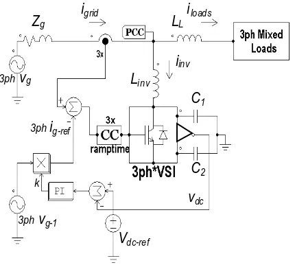
In this paper, the three-phase shunt APF is a combination of a grid current-controlling shunt APF integrated with a series reactor installed at the Point of Common Coupling (PCC) to handle the harmonic and unbalance problems from mixed loads (see Figure 1) [3]. T his novel shunt APF has been developed to overcome the problems occurred in the conventional shunt APF.
Note: Discussion is expected before June, 1st 2007. The proper discussion will be published in Electrical Engineering Journal volum e 7, num ber 2, Septem ber 2007.
Conventionally, the power inverter as a shunt APF is controlled in such a way as to inject equal-but-opposite harmonic and reactive compensation currents based on calculated reference currents. Hence, the current sensors are installed on the load side. T hen, their output signals will be processed to construct the reference or desired currents, which consist of harmonic and reactive components as well as negative- and zero-sequence components for unbalance compensation. Once the desired reference currents have been established, the currents must be injected into the grid accurately using a current control mechanism. T he actual inverter currents must attempt to follow the reference currents with high bandwidth. In addition, the DC-bus voltage has to be kept constant to compensate for the inverter losses.
iloads
igrid
iinv
3ph vg
Zg
vdc
Vdc-ref
LL
Linv
C1
C2
3ph ig-ref
k
3ph vg-1
Figure 1. Block diagram of the shunt APF
T here are many advantages of directly controlling the grid current. Firstly, it is easy to create a simple sinusoidal reference for the grid current. T he reference current is an appropriate reference to minimize the grid harmonic currents. Secondly, the grid currents produced will be sinusoidal, balanced and in phase with the grid voltage regardless of grid voltage conditions. T hus, it prevents (more) pollution of the electrical system from non-linear loads. Furthermore, there are three current sensors installed at the grid side instead of six current sensors in a conventional shunt APF. T he control mechanism becomes very simple as well.
Moreover, a shunt APF cannot properly compensate for harmonic voltage sources. In many cases, non-linear loads consist of combinations of harmonic voltage sources and harmonic current sources, and may contain significant load unbalance (ex. single phase loads on a three phase system). The addition of a small series inductance, XL is simple, effective and practical not only to provide the required voltage decoupling between voltage type of load harmonic sources and the PCC but also to reduce the bandwidth of the load harmonic currents [4].
Due to its functions, the existence of the shunt APF may change the distribution of power between the grid and the load. Hence, power is flowing in the grid, the load and the inverter. It is expressed in terms of real power and imaginary power, which consist of an average value and an oscillating value. The relation-ship of these terms to the conventional concept about active, reactive and harmonic power can be seen in [5]. In this paper, power flow in the power system as well as in the shunt APF will be investigated.
SHUNT AC TIVE PO W ER FILTER O PERATIO N
T he phase shunt active power filter is a three-phase current-controlled voltage-source inverter (CC-VSI) with a mid-point earthed split capacitor (C1 and
C2) in the DC bus and inductors (Linv) in the AC output. T hus, it is essentially three independent single-phase inverters with a common DC bus.
T he APF consists of two control loops, namely an inner control loop and an outer control loop. The inner control loop is a ramptime current control [6][7] that shapes the grid currents to be sinusoidal by generating a certain pattern of PWM for continuous switching of the inverter switches, while the outer control loop is a simple Proportional Integral (PI) control to keep the DC bus voltage constant and to provide the magnitude of reference current signals.
Dire ct C ontrol of the Grid C urre nt
In this scheme (see Figure 1), the CC-VSI is operated to directly control the AC grid current rather than it’s own current. T he grid current is sensed by putting the current sensors on the grid side and forced to behave as a sinusoidal current source. T he grid appears as a high-impedance circuit for harmonics. By forcing the grid current to be sinusoidal, the APF automatically provides the harmonic, reactive, negative and zero sequence currents for the load, following the basic current summation rule:
igrid = iinverter + iloads (1)
T he sinusoidal grid current reference signal is given by:
ig-ref = k vgrid-1 (2)
where vgrid-1 is the fundamental component of the grid voltage, and k is obtained from an outer control loop regulating the CC-VSI DC-bus voltage. This can be accomplished by a simple PI control loop. This is an effective way of determining the required magnitude of active current required, since any mismatch between the required load active current and that being forced by the CC-VSI would result in the necessary corrections to regulate the DC-bus voltage.
Se rie s Inductance [4]
Another key component of this system is the added series inductance XL, which is comparable in
value to the effective grid impedance, Zg. Without this
APF. Currents from the APF do not significantly change the harmonic voltage at the loads. Therefore, there are still harmonic voltages across the grid impedance, which continue to produce harmonic currents. T he inductance XL provides the required
voltage decoupling between load harmonic voltage sources and the grid.
PO W ER INVERTER MO DEL
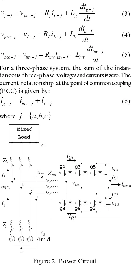
T he three-phase power distribution system with the shunt active power filter along with integrated series inductors is described in Figure 2. T he devices are assumed to be the same for the three phases. Applying Kirchoff’s rules to this system, the voltages of the grid, the load and the output inverter are given by:
For a three-phase system, the sum of the instan-taneous three-phase voltages and currents is zero. The current relationship at the point of common coupling (PCC) is given by:
Figure 2. Power Circuit
By controlling the switches, the PWM CC-VSI output voltages vinv-j can be expressed in terms of
DC-bus voltages (assuming the voltages are constant over the switching period) and the continuous duty ratios of the switches, which is denoted by dj: expression for dj in terms of the voltages can be found directly from equations (7) and (8):
dc
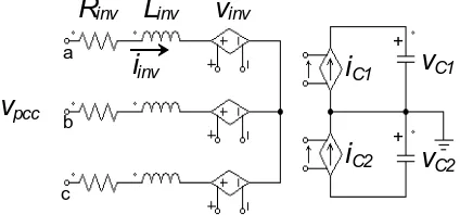
T herefore, as seen from the AC side, the power inverter (converter) can be modelled in time average as a voltage-controlled voltage source (VCVS) with the parameter of vinv.
On the DC side, the modelling begins with the expression of the current through each bidirectional switch Qj. For phase A, the average current iQ1 is equal to da iinv-a, while iQ4 is equal to (da – 1) iinv-a. T hus, in general, the average bidirectional switch currents can be written as functions of inverter output currents, namely:
j
On the DC side, the current flowing to capacitor C1 is
iC1, and to capacitor C2 is iC2. The currents iC1 and iC2 each are equal to the total currents through their respective bidirectional switches, and are simply expressed as follows:
∑
T hus, on the DC side, the converter is modelled in time average by a current-controlled current-source (CCCS) with DC-capacitor currents.
)
Based on equation (7) and equations (12) and (13), the inverter equivalent circuits can be illustrated as in Figure 3.
Figure 3. Equivalent Circuit of the Inverter
PO W ER FLO W
Power flow analysis of this system in steady state is similar to that undertaken by Akagi [8][9]. Considering a non-sinusoidal and unbalanced system, the load power consists of real power pL, imaginary power qL and zero sequence power pL-0 , which consist of an average value and an oscillating value as mentioned above:
T he shunt active power filter has to compensate for the unwanted currents of the load so that after successful compensation, the grid currents will be sinusoidal and in-phase with the grid voltage. As a result, if the grid voltage is non-sinusoidal and/or unbalanced, the powers pg, qg and pg-0 generated from the grid become:
g
T o achieve sinusoidal grid currents, both powers
p
~
gand
q
~
g still exist in the grid in small values. The power developed by the inverter is calculated by subtracting the power supplied by the grid and the power consumed by the load, given by:⎥ expressed in terms of average and oscillating values as:
From Equation (19), the characteristics of the power flow in the system can be described as follows: 1. T he inverter supplies the zero sequence average
(active)
p
L−0 and oscillating~
p
L−0 power needed by the load.2. T o supply the load zero sequence active power, the inverter has to take an active power from the grid because the inverter has no DC source (only DC capacitors in the DC bus). Neglecting the losses in the power converter, in steady state, the active power consumed by the load is equal to the active power supplied by the grid, and total active power flowing to the inverter is zero. The active (average) power in Equation (19) can be combined as: taken from the grid by the inverter, which is used to support the zero sequence power delivered to the load, is
p
inv=
p
g−
p
L=
p
L−0. Additional power consumption is required to compensate forthe losses, so that loss an energy storage element. Hence, this power will appear in the DC-bus voltage ripple. Normally,
g
p
~
is small so that the DC-bus voltagepredominantly reflects the load power. 4. T he inverter controls the whole imaginary power
associated with the load
q
L+
q
~
L and the gridq
~
g.SIMULATIO N RESULTS
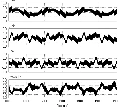
reactive and unbalanced currents. It is obvious that the CC-VSI is able to generate three different currents for each phase as well as the neutral current, as shown in Figure 7. Hence, the inverter also provides balancing to create the symmetrical grid currents.
Figure 4. Grid voltages - unbalance and harmonics
Figure 5. Load currents
Figure 6. Grid currents after compensation
Figure 7. Inverter currents
Figure 8 shows the relationship of the real power from the grid, the load and the inverter. It is clear that pinv = pg – pL . Both waveforms are the same and contain a small average value, which corresponds to zero sequence power as well as losses absorbed by the CC-VSI. Figure 9 shows that the zero sequence power of the load is compensated for by the CC-VSI, while the zero sequence power of the grid is close to zero. Thus, the grid supplies the required zero sequence active power to the inverter, and then the inverter delivers the power to the load. From Figure 10, the relationship of the imaginary power from the grid, the load and the inverter is demonstrated. Finally, the grid supplies the real power as shown in Figure 11, which agrees with Equation (17). The grid generates a small reactive power
q
g because the grid currents lead thevoltages by approximately 1o due to the
high-frequency switching filter. Shifting the grid reference current by a small negative value can eliminate the reactive power. Hence, computer simulation results verify the power flow in Equation (19).
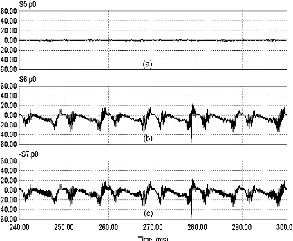
Figure 9. Zero sequence power (a) pg-0 (b) pL-0 (c) pinv-0
Figure 10. Imaginary power (a) qinv (b) qg - qL
Figure 11.Power from grid (a) real power (b) imaginary power (c) zero sequence power
T he power characteristics of the inverter have to be reflected in the power at the DC bus. The power at the DC bus can be given by:
Substituting Equations (21) and (22) into (20) for P
dc-bus yields:
T he DC capacitor currents may contain a zero sequence current; however, the power at the DC-bus is free from zero sequence current. From (23), the power at the DC bus predominantly depends upon the first part of the equation. Multiplying vpcc and iinv at the same phase results in instantaneous real power and instantaneous zero sequence power. T he zero sequence power can exist in the DC bus depending upon both the zero sequence current from the load and the zero sequence voltage at the PCC.
T he DC bus does not contain imaginary power. This fact agrees with the concept of instantaneous reactive power compensation using switching devices without energy storage [7]. T he CC-VSI generates qinv but it does not flow out of or into the DC-bus capacitors. According to Watanabe [9] and Peng [10], the imaginary power circulates among the phases. In other words, instantaneously, the imaginary power required by one phase can be supplied by the other phase.
T he DC-bus capacitors absorb the small active power to compensate for the losses in order to keep the DC voltage constant.
C O NC LUSIO N
model, on the AC side, the CC-VSI can be represented as a voltage-controlled voltage source; while on the DC side, a current-controlled current source represents the inverter.
From power flow analysis, the power distribution in the grid, loads and the inverter is identical to the system with conventional APF. It is obvious that the shunt APF is able to enhance the power capacity of the grid by compensating for the non-active power. T he inverter controls the imaginary power and the zero sequence power. However, the non-active power does not emerge in the DC bus. T he DC bus only contains real power as well as zero sequence power. Computer simulation and experimental results clarify the theoretical observations.
REFERENC ES
[1] M. El-Habrouk, M.K. Darwish and P. Mehta,
“Active Power Filter: A Review”. IEE Proc.
Electr.Power.Appl, September 2000, pp. 403-413.
[2] B. Singh, K. Al-Haddad and A. Chandra, A
“Review of Active Filter for Power Quality
Improvements”. IEEE Trans. on Industrial
Electronics, February 1999, pp. 960-971. [3] T umbelaka, H.H., L.J. Borle, and C.V. Nayar,
“Application of A Shunt Active Power Filter to Compensate Multiple Non-linear Loads”. in
Australasian Universities Power Engineering Conference (AUPEC). Melbourne, Australia: ACPE, 2002.
[4] T umbelaka, H.H., L.J. Borle, and C.V. Nayar, “Analysis of a Series Inductance Implementation on a T hree-phase Shunt Active Power Filter for Various T ypes of Non-linear Loads”. Australian Journal of Electrical and Electronics Engineering, Engineers Australia, 2005. 2(3): pp. 223-232.
[5] Watanabe, E.H., R.M. Stephan, and M. Aredes, “New Concepts of Instantaneous Active and Reactive Powers in Electrical Systems with
Generic Loads”.IEEE Transactions on Power
Delivery, 1993. 8(2): p. 697-703.
[6] L. Borle, Zero average current error control methods for bidirectional AC-DC converters.
PhD thesis, Curtin University of Technology and the Australian Digital T heses Program: http://adt.caul.edu.au/
[7] L. Borle and C. V. Nayar, “Ramptime Current
Control”. IEEE Applied Power Electronics
Conference (APEC’96), March, 1996, pp 828-834.
[8] Akagi, H., Y. Kanazawa, and A. Nabae, “Instantaneous Reactive Power Compensators Comprising Switching Devices without Energy
Storage Components”.IEEE Transactions on
Industry Applications, 1984. IA-20(3): p. 625-630.
[9] Akagi, H., S. Ogasawara, and H. Kim, The
Theory of Instantaneous Power in Three-phase Four-wire Systems: A Comprehensive Approach. in IEEE IAS Annual Meeting. 1999. p. 431-439
[10]Peng, F.-Z., G.W. Ott, and D.J. Adams, “Harmonic and Reactive Power Compensation based on the Generalized Instantaneous Reactive Power T heory for T hree-phase Four-wire
Systems”.IEEE Transactions on Power