PROJECT ARCHEYE – THE QUADROCOPTER AS THE ARCHAEOLOGIST’S EYE
Christian Seitz and Holger Altenbach
Interdisciplinary Center for Scientific Computing Institute for Pre- and Protohistoric Archaeology
Heidelberg University
Im Neuenheimer Feld 368, 69120 Heidelberg
[email protected], [email protected] http://www.archeye.de
KEY WORDS:UAVs, Archaeology, Documentation, Photogrammetry, Flight planning
ABSTRACT:
In archaeological research the exploration of archaeological monuments from the air has a long tradition and thus can be seen as a necessary component. At this point our project ‘ArchEye’ steps in as a cheap and flexible method and also as a new way to document different archaeological areas and objects without using manned aircrafts.
1 INTRODUCTION
A complete overview map of an archaeological excavation site is a valuable tool for planning reconstruction work, cataloguing findings, and determining areas of risk. However, most projects don’t have the financial funds or the local authorization to employ aerial observation techniques (plane or satellite) to create such maps.
In the project ArchEye we use a mechanical semi-autonomous quadrocopter equipped with a digital camera. There are two main tasks at the moment:
We compile overview and detail maps by combining (stitching together) several individual digital photographs. By covering the complete site with a set of overlapping photos, deskewing and stitching them together, maps of high resolution and quality can be produced in a short time without being in need for a manned plane flight.
The second task is using the quadrocopter to create a three-di-mensional model out of a set of photos, taken all around an ob-ject of interest, like remains of walls, strongholds, buildings and so on. This model can be processed in different ways and for different archaeological tasks.
The project tests a new platform for such autonomous flights and determines the practical needs of archaeologists in terms of qual-ity, resolution and global mapping.
In a first phase, ArchEye uses a low-cost quadrocopter as the technical basis for the flight. First experiments with this platform showed the high potential of the approach as well as the wide variety of further applications that we can tackle. A more pow-erful platform based on a different UAV is planned for further assignments such as aerial survey for photogrammetry of tem-ple structures, placement of independent sensors to monitor local climate changes due to deforestation, and also reconstruction on excavation sites.
This project started as a students practical course in software en-gineering at theInterdisciplinary Centre for Scientific Computing (IWR)of Heidelberg University, supervised by Dr. M. Winckler. As it seemed very promising, theHeidelberg Graduate School (HGS)and theMethods and Applications Collegium (MAK), all Heidelberg University, joined in with financial support to pur-chase the components for the quadrocopter.
After some time of developing, testing and setbacks, we were able to create our first achievements with this method in Febru-ary 2010. Since then we advanced by using better cameras and therefore improved our results.
2 ARCHAEOLOGY
When we started our project, we were two students of archaeol-ogy having a minor field of study in computer science and search-ing for a practical in computer science. We did not know which way to go, but we wanted to do something that should connect the archaeological work with the computer science.
In our department the Late-Bronze-Age of the palace of Tiryns in Greece is a main field of research by Prof. J. Maran. There is an aerial photo hanging in the corridor of the department, showing the whole palace of Tiryns. One can clearly see, it was made by a blimp or balloon, because you can see the line holding it. This picture made us think about a way to use the advanced technology to improve this technique. Photos like these are not only valuable for an overview of an area, but also to record the features during the various levels and different plana of archaeological excavation work.
Most archaeological features are recognised as colour changes in the soil. Therefore it is very useful to take a photo of them from a higher position, but without the use of a UAV there were only dangerous, expensive or time-consuming methods, like aerial pho-tos taken from manned aircraft, climbing a telephone-post and so on. But all of these methods do not result in orthogonal projected photos.
Right from the start we had the possibility to attend the excava-tion in Neuhofen, near Ludwigshafen, Germany (see secexcava-tion 8.1). We also took part at the training excavation of our department at Hassloch, Rhineland-Palatine, Germany (see section 8.3).
3 THE QUADROCOPTER
3.1 Decision
Figure 1: The quadrocopter flying with the camera ready.
to be discussed and had their pros and cons. In search for infor-mations about gas-driven model helicopter we found the website of mikrokopter.de and we set this UAV on our competitors list. Soon we recognised that we couldn’t use gas-driven models be-cause in Germany they are not allowed to fly closer than 1,5 km to a city. Model airplanes needed too much space for flying and cannot hover, which makes them interesting only for large areas. A blimp would have been a perfect platform for taking photos, but for the size of camera we wanted to use, the blimp would have to be about three to four meters long. Furthermore it takes a lot of time to get it ready for take-off, and it is very susceptible to wind. All in all it was too large and cumbersome, also the helium was too expensive. Therefore the quadrocopter was getting more and more interesting.
The quadrocopters built by the mikrokopter.de project showed us, what huge potential they have. Finally we decided for a quadro-copter. The detailed data of this UAV will be shown in section 3.2. We can fly it even inside of buildings like churches or halls. This UAV can hover on a spot, it is agile and can load about 700g of payload with a flight duration of at least 10 minutes.
3.2 Control unit
The control unit is developed and made by mikrokopter.de, a Ger-man project developing micro-controllers and software for multi-copters with a broad community of supporting users. At present it consists of two basic units. The first one, the so called Flight-Ctrl, is for the basic calculation of flying manoeuvres to keep the copter balanced. It has three gyroscopes, one for each ro-tation axis, and a three axes acceleration sensor to measure the position. The second one is for navigation purposes and called Navi-Ctrl. It is highly modular, using additional sensors like a magnetic compass and GPS with antenna. On each plate is work-ing a Atmel ATMEGA Processor, givwork-ing the quadrocopter fairly much processing speed for each task. With this equipment, the quadrocopter can fly semi-autonomous along a GPS-based path taking photos. Only take-off and landing are done by the pilot. We can also monitor the flightdata on our notebook and change the flight plan in real-time.
3.3 Frame
We are using a carbon-fibre frame developed by powerframe.de (see fig. 1). It is lightweight, robust and provides good mounting of bigger cameras. Below the frame the camera is mounted, cur-rently a Samsung NX-100 with 14 MPx. This mounting is coun-terbalancing the steering movements of the quadrocopter and also
reduces the transfer of vibrations to the camera, caused by en-gines and air-screws. The counterbalancing is calculated by the Flight-Ctrl and driven by two servos. The camera can also be tar-geted to a point of interest, not only in orthogonal angle. This is especially important for the three-dimensional documenting of buildings which will be in focus at every altitude and angle. The resulting photos are covering the object from all sides to reduce holes in the model.
3.4 The Drive
The engines are developed and manufactured by AHM Brushless, Germany. These outrunner engines produce with the 12” glass-fibre air-screws about 1150 g thrust per motor. This is enough to lift a bridge-camera for 10 to 15 minutes using a 5000mAh battery. If the battery is empty, only a short stop is necessary to change it and to continue the flight.
4 WORKFLOW
Our workflow is structured in five main steps, each consisting of several substeps:
1. Flight preparation
Defining a rectangular area to be recorded, using the coordi-nates of the lower left and the upper right corner in GPS, Lat-Long or UTM coordinates. With the two in the last step defined points, the camera- and lensdata, the altitude or the intended resolution of the resulting data (see section 5), the waypoints are calculated. The calculated waypoints are transferred via a wireless interface to the Navi-Ctrl of the quadrocopter.
2. Flight
At this stage of the project, manual starting and landing is necessary. Once in the air, the quadrocopter is switched over to automatic mode to fly to the calculated waypoints, navigated by GPS. At each spot it takes five photos before moving to the next waypoint. After completing the route it returns to the starting point, where the quadrocopter has to be manually landed.
3. Photo processing
After the flight, the pictures are transferred to a notebook or a pc, where they are reviewed. The photos are merged (‘stitched’) to a single high resolution photo using the open-source software Hugin. The result has to be reviewed for graphical errors like wrongly aligned single photos, which may appear if not enough controlpoints are found.
4. Deskewing
The resulting picture has to be deskewed using measured passpoints to remove distortion caused by the stitching pro-cess. This task is executed either with a GIS or a CAD ap-plication.
5. Documentation and post processing
Using these applications, further archaeological tasks are done with these georeferenced photos (see section 6). Using the various unstitched photos, we can also calculate a 3D model out of a set of photos (see section 7)
5 SOFTWARE
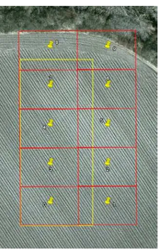
For the operating at excavations, we created a program for the calculation of a flightpath, depending on the area, camera- and lensdata and either by altitude or by intended resolution. Now we can input two GPS-points defining a rectangular area bound-ary, and the program calculates a point-based track, considering the necessary overlap of each photo (see fig. 3). The program then returns a file with the waypoints listed, which can directly be used by the control program for the quadrocopter. Additionally the program outputs a KML file to control the waypoints and the camera’s field of view visually in GoogleEarthc (see fig. 4). At each point the quadrocopter takes five photos to minimize blur-ring before continuing its flight to the next point. After it visited every waypoint, the quadrocopter returns to the starting point or a manual set coordinate.
6 PLANAR STITCHING AND GEOREFERENCING
The orthogonal photos taken along the waypoint track are cal-culated with 40% overlap to stitch them to a single high-resolu-tion photo. This task is currently done by the open source soft-ware Hugin. The result on one hand gives an overview of the
Figure 3: The software.
Figure 4: The area (yellow) and the resulting waypoints (yellow pins) with the calculated field of view of the camera (red, overlap is not displayed) in GoogleEarthc
excavation-area and on the other hand a detailed view by zoom-ing in if needed. Because the resultzoom-ing photo is large, it can be printed in a large format showing all the details.
7 WORKING IN THREE DIMENSIONS
In general the 3D data are calculated out of a set of photos. At the moment we are evaluating different commercial and open source software tools like MeshLab. The generated pointcloud can be processed to a mesh and colourized with the colour of the single points at this position. The result is a quite good model and can even show some details. Of course there are a lot of possibilities for further development in this aspect.
There are three possibilities using the quadrocopter photos in 3D modelling:
The first is to take the rectified photos to calculate a 3D model. The result provides a good method to differentiate features on a planar area like an excavation or field.
The second is to combine the aerial photos and the ones taken free-hand with the same camera on the ground, to calculate a complete three-dimensional model of an object or a building. Be-cause using the detached camera of the quadrocopter by foot, the whole data acquisition is simple and very fast. The result-ing model, of course, cannot be compared to models created by a laser- or structured-light scanner, but it is possible to get a three-dimensional impression of the object. This is sufficient for most archaeological problems.
The last one is to combine the model calculated by the aerial pho-tos with an incomplete model of a ground-based scanner, like a laser- or structured-light scanner. This helps to fill missing parts or gaps in the model, primarily views from above or other areas difficult to reach.
8 RECENT WORK
8.1 Neuhofen, Germany (Stitching)
Figure 5: Detail of fig. 10 Neuhofen, Germany.
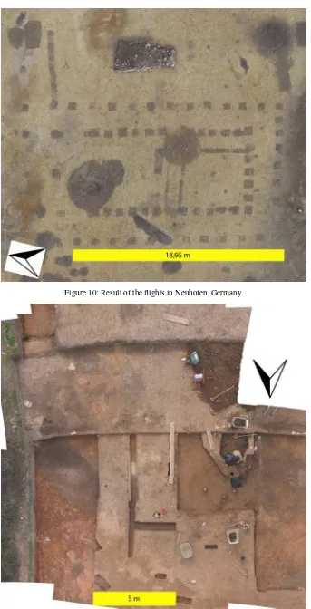
In September and October 2010 we supported the excavations in Neuhofen near Ludwigshafen, Germany. In the area of the excavation is a wooden roman fort, where the related settlement, the so called vicus, was examined. In the area of the vicus a hall was discovered which we documented in several flights over the excavation. The result is a high resolution photo showing, in all details, the postholes of the building and the other features around (see fig. 10), like a collapsed stone building, probably used to dry the harvest. It is our best result and with 6100 by 3700 pixels also the biggest. Here we can show very clearly the power of this method, because you can zoom into this photo to the very details. It is actually possible to draw the stones of the drying house (see fig. 5).
8.2 Banteay Chhmar, Cambodia
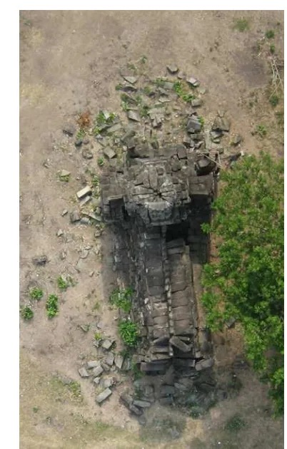
Figure 7: View of the south-east-gallery in Banteay Chhmar, Cambodia.
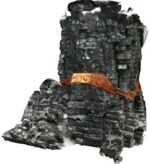
Figure 8: Model of the tower 18, Banteay Chhmar, Cambodia. quadrocopter. Unfortunately the area was full of trees so there was no possibility to fly. The results without the overhead view are quite good, anyway.
8.3 Hassloch, Germany
In February and March 2011 we took part in the teaching exca-vation of our department in Hassloch, Rhineland-Palatine, under direction of the ‘Generaldirektion Kulturelles Erbe, Außenstelle Speyer’. The excavation is examining a settlement of the
Band-Keramik culture, a late neolithic culture. We documented two steps of the excavation by overviews and created one 3D-model. Stitching Due to the windy, cold and rainy weather we could not make many flights in Hassloch. We only had two plana where we could fly under difficult conditions. The result is one photo of the area, while the work for the third planum is in progress, see fig. 11. In full resolution, this photo has 9300 by 9200 pixels and was taken with a Samsung NX-100.
3D We also could use the single photos to create a 3D model of the excavation area. Although we were not very confident to get any 3D data, the result shows clearly the advantages using an UAV on an excavation. We could use a colour filter to show the different heights using GigaMesh, a tool created by H. Mara at the IWR. Visualizing the trenches and the different heights of the plana is one of the main advantages (see fig. 9).
Figure 9: 3D model of planum three of the excavation at Hass-loch.
9 CONCLUSIONS AND FUTURE WORK
With our little project we wanted to explore the possibilities of a UAV for archaeological tasks. After several tests and after some flights we are at a point where we can claim that a UAV could get a standard tool on excavations. Its possibilities to get fast overviews, to document and even to do 3D modelling makes it a universal tool for archaeologists.
The next steps are to improve the reliability of our UAV, to in-crease the payload and improve the overall quality of the resulting photos and models.
ACKNOWLEDGEMENTS
The authors would like to thank Dr. Michael Winckler (IWR, HGS) for the initiating support of our project and Prof. Dr. Tho-mas Meier, Institut f¨ur Ur- und Fr¨uhgeschichte, for his advises in archaeological tasks. We will also do our magister thesis under their supervision. Further we thank the Methods and Applications Collegium, which also kindly supported us.
Figure 10: Result of the flights in Neuhofen, Germany.