ASPECTS OF DEM GENERATION FROM UAS IMAGERY
A. Greiwea,∗ , R. Gehrkea,∗ , V. Spreckelsb,∗ , A. Schlienkampb,∗
a
Department Architecture, Civil Engineering and Geomatics, Fachhochschule Frankfurt am Main, Germany
{ansgar.greiwe,ralf.gehrke}@fb1.fh-frankfurt.de
b
RAG Aktiengesellschaft, RAG Deutsche Steinkohle, Geschaeftsbereich Standort- und Geodienste, Herne, Germany
{volker.spreckels,andreas.schlienkamp}@rag.de
Commission I, ICWG I/5
KEY WORDS: DEM generation, micro UAS, camera calibration, Foveon
ABSTRACT:
Since a few years, micro UAS (unmanned aerial systems) with vertical take off and landing capabilities like quadro- or octocopter are used as sensor platform for Aerophotogrammetry. Since the restricted payload of micro UAS with a total weight up of 5 kg (payload only up to 1.5 kg), these systems are often equipped with small format cameras. These cameras can be classified as amateur cameras and it is often the case, that these systems do not meet the requirements of a geometric stable camera for photogrammetric measurement purposes. However, once equipped with a suitable camera system, an UAS is an interesting alternative to expensive manned flights for small areas.
The operating flight height of the above described UAS is about 50 up to 150 meters above ground level. This low flight height lead on the one hand to a very high spatial resolution of the aerial imagery. Depending on the cameras focal length and the sensor’s pixel size, the ground sampling distance (GSD) is usually about 1 up to 5 cm. This high resolution is useful especially for the automatic generation of homologous tie-points, which are a precondition for the image alignment (bundle block adjustment). On the other hand, the image scale depends on the object’s height and the UAV operating height. Objects like mine heaps or construction sites show high variations of the object’s height. As a result, operating the UAS with a constant flying height will lead to high variations in the image scale. For some processing approaches this will lead to problems e.g. the automatic tie-point generation in stereo image pairs.
As precondition to all DEM generating approaches, first of all a geometric stable camera, sharp images are essentially. Well known calibration parameters are necessary for the bundle adjustment, to control the exterior orientations. It can be shown, that a simultaneous on site camera calibration may lead to misaligned aerial images. Also, the success rate of an automatic tie-point generation differs extremely between several photogrammetric software packages.
In this article, the calibration results of a suitable camera system will be shown. For a small format consumer grade camera, the authors will give the proof of ability for photogrammetric measurements purposes. This includes the results of different processing approaches for DEM generation of environments showing high object height variations.
1. INTRODUCTION
Since a few years, micro UAS (unmanned aerial systems) with an overall weight up to 5 kg and vertical take off and landing (VTOL) capabilities are used as sensor platform for Aerophotogrammetry (Eisenbeis 2009). These micro-UAS are equipped with a GPS Sensor and allow an autonomous photogrammetric flight. However, the restricted payload (1,5 kg) of these systems leads to the use of small format cameras (Gehrke et.al. 2011). These lightweight cameras can be classified as amateur cameras and it is often the case, that these systems do not meet the requirements of a geometric stable camera for photogrammetric measurement purposes. However, once equipped with a suitable camera system, an UAS is an interesting alternative to capture the ground surface by aerial imagery compared with expensive manned flights (Grenzdörffer 2008).
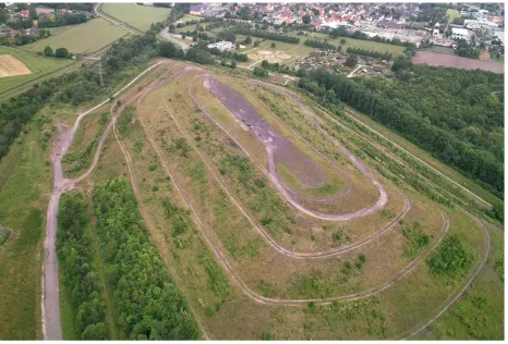
Due to legally restrictions in Germany, the UAS flights have to be carried out in line of sight of the remote pilot. Flight authorizations by governmental authorities define this line of sight as a distance of about 250 m. This restrictions permit the use of UAS for small areas or objects like construction sites or mine heaps. In Northrhine-Westphalia, near Hamm, the mine heap “Halde Humbert” is used as study area for this paper. The area of this object is about 600 m by 300 m and about 40 m height above ground level.
The overall goal of this study was the measurement of a digital surface model of the area by use of aerial imagery taken with a small format camera and a micro UAS as sensor platform.
Figure 1. Study Area “Halde Humbert”
2. UAS AND CAMERA
a lightweight compact camera would permit the use of heavier batteries which would increase the flight time. As an example, the use of an 800 g DSLR would allow the use of an 575 g battery. The capacity of 5800 mAh leads to an operational flight time of about 12 minutes. Under the same weather conditions, a compact camera with a weight of about 250 g would allow a 1150 g battery with a capacity of 11600 mAh. This configuration nearly doubles the flight time to approx. 20 minutes.
Figure 2. MR-X8 with two axis stabilized camera mount
The camera mount includes an active roll and pitch compensation which is controlled by the UAS. This mount allows a shutter speed of about 1/1000 sec and leads to well aligned aerial image footprints. Nevertheless, sometimes faster shutter speed ratings are necessary to prevent motion blur. These short shutter speed setting can lead to under-exposed imagery. Other image artefacts are inappropriate settings for the sensor's white balance. Storing the imagery in RAW data format allows an image enhancement by a manual postprocessing (Verhoeven 2010).
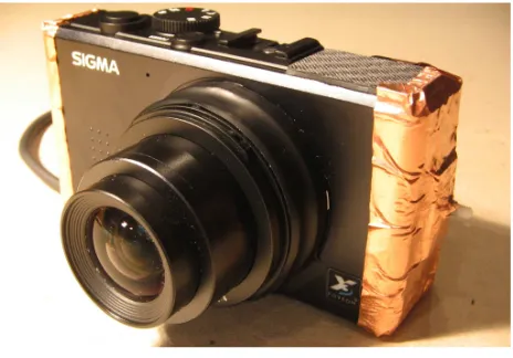
The Sigma DP1 is a compact camera with RAW data storage capabilities and thus fulfilling the above described requirements. The camera is equipped with a prime lens realizing a focal length of 16,6 mm (wide-angle).
Figure 3. Modified Sigma DP1
As a precondition for the use as photogrammetric sensor, the lens tube can be locked by epoxy compound to realize a fixed focal length. Although this camera is a lightweight sensor
compared to DSLR, the camera's sensor has nearly the same size (APS-C , see the following table 4).
Weight Focal
The Sigma DP1 is equipped with a FOVEON X3 sensor. This sensor utilizes the depth of penetration of the electromagnetic spectrum into the silicon chip. Differently to DSLR Sensors with bayer pattern (each pixel has a filter = one single color), the FOVEON technology is able to store all components of visible light (red, green, blue) in one pixel (Gilblom et al. 2003). This methodology lead to a very high contrast modulation capability which results in a very high image quality (Greiwe & Gehrke 2013).
Due to the stabilization of the camera's lens tube, the authors were able to calibrate the sensor by use of a 3D test field in the laboratory. The interior orientation parameters like principal point (x'0, y'0) the focal length (c) and the radial distortion
parameter (A1, A2) were estimated in three measurements. The
following table 5 shows the differences between the calibration result, setting the first measurement as reference. Due to the results the camera's lens tube can be assumed as stable.
Table 5. Calibration results of a modified Sigma DP1
3. PHOTOGRAMMETRIC FLIGHT
The MR X8 is able to fly in a semi autonomous mode. Predefined waypoints can be stored in Google KML format. In this KML file, the position and the heading are stored and can be transferred by a mobile ground control station during the flight. Once the copter receives a new waypoint from the ground control station, the platform rotates to the heading of that waypoint and moves to the desired position, holding the heading during the flight to that waypoint. The height must be controlled by the remote pilot on the ground since the MR X8 does no full 3D waypoint navigation. As a consequence, the start and endpoints of a flight line were defined and the flight height above ground level was planned with 100 m. With the given focal length of 16.6 mm, this configuration results in a GSD of 4.7 cm on top and about 7 cm on the ground of the mine heap (140 m flying height).
The image acquisition is executed in a constant time interval of five seconds. Flying between two waypoints with a constant heading, this practise leads to the desired flight strips for the aerotriangulation. The resulting baseline follows from the average flight speed of the MR X8. A speed of 3 m/s leads to a baseline of 15 m which equates to a forward overlap of about 80%. The distance between two neighbouring flight lines was planned with 100 m which equates a side overlap of about 30%.
oblique imagery with a tilt angle of 45° were planned. Within three flights, all planned lines were successfully completed. After the flight, 25 images of each flight line were manually checked in terms of image quality and stored as 16 bit TIFFs for further processing. The following figure shows the flight paths for the nadir images (green) and the oblique image acquisition flights.
Figure 6. Flight paths over study area
4. AEROTRIANGULATION
The UAS imagery were processed using different software packages. The first group (LPS ATE V9.1, SOCET SET V5.5) are designed for the standard aerial photogrammetry case. With each package, a digital surface model (DSM) was generated.
For the tests, the pit heap was covered with 16 ground control points, measured by differential GPS and each signalized by a checkboard like pattern.
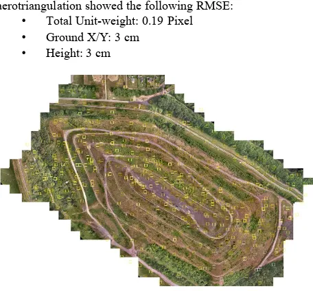
Figure 7. Distribution of ground control points
Within LPS ATE, first of all the block configuration was set up with approximate values for the exterior orientation taken from the flight planning. Control points were measured manually. In
a first attempt the tie points were generated automatically. The results of this procedure yielded in a large number of blunders, which had to be checked manually. The errors occurred mostly in areas with a variable image scale due to the constant flying heights and the variable ground elevation (image height was 100 m on top of the pit heap and 140 m on ground level).
Figure 8. Image footprints and tie-points
As shown in figure 8, the last flight strip (bottom) has no straight forward heading as the other two adjacent flight strips. This effect arises due to an manual UAS navigation error by the remote pilot. Consequently the image matching algorithm showed a lower performance and this led to a significant lower number of automatically generated tie points.
The results of the aerial triangulation (RMSE) were as follows: • Total image Unit-Weight: 0.28 Pixel
• Ground X/Y: 1 cm • Height Z: 2 cm
SECET SET was used as the second software package covering the standard aerophotogrammetry case. Like in LPS ATE, the same nadir images and check points were used for
aerotriangulation. The automatic tie point generation also failed in many cases due to the variable image scale and the misaligned third flight strip. As a consequence, 518 tie points were checked manually (see figure 9). The results for the aerotriangulation showed the following RMSE:
• Total Unit-weight: 0.19 Pixel • Ground X/Y: 3 cm
• Height: 3 cm
Both software packages, LPS and Socet Set make exclusive use of nadir imagery which is characteristic for the standard aerial case. However, oblique imagery was also collected by the UAS, which could not be taken into account by the above described software packages. Thus the authors decided to use an additional software package (Agisoft PhotoScan) to process all images (nadir and oblique). This software package is designed for aerial and close-range photogrammetry. Based on a SIFT operator, the software is able to detect tie points in nadir as well as oblique imagery. The SIFT features are used to align the photos in a first step to produce a sparse point cloud (see figure 10). In a second step, after measuring the ground control points, an aerotriangulation is performed producing a dense point cloud. Photoscan is able to detect blunders by calculating the reprojection error of an SIFT feature.
Figure 10. Sparse point cloud with aligned aerial images
In a first attempt, all nadir images were used to produce a dense point cloud. 414,000 points were detected in the present nadir imagery. After rejecting all points with an reprojection error of more than 0.3 pixel, 249,000 tie points were accepted for the aerotriangulation. The results for the aerotriangulation showed the following RMSE:
• Total Unit-weight: 0.31 Pixel • Ground X/Y: 1 cm
• Height: 2 cm
5. DIGITAL ELEVATION MODEL
For each software package, a digital elevation model (DEM) was calculated. The models were imported in a GIS and the absolute difference of the height values was estimated as shown in the following figures.
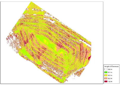
Figure 11. Height differences LPS ATE and SOCET SET
Figure 12. Height differences LPS ATE and PhotoScan
Figure 11 and figure 12 show some effects which occur from the DEM generattion methodology in LPS ATE. This software package creates the DEM only from stereo image pairs. A higher number of image measurements caused by the high forward overlap of about 80% is neglected by this software. In the lower left area in both figures is also visible the effect of slightly misaligned aerial images. Differences of less than 10 centimetres can only be observed in flat regions on top or at the bottom of the pit heap.
The differences between SOCET SET and PhotoScan shown in the next figure are much lower compared to the differences with LPS.
Figure 13. Height differences between Socet Set and PhotoScan
Flat terrain or bare soil surface showed only differences within 10 cm up to 20 cm. The highest height deviations can be observed in areas with vegetation (compare figure 1).
6. OBLIQUE IMAGERY
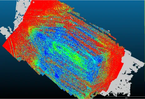
Finally, the dense point clouds were compared by computing the closest distance (scalar filed) between the point clouds.The results can be observed in the following figure.
Figure 14. Distance (scalar field) between point clouds
All points marked red in figure 14 show a distance of more than 20 cm. In flat and open areas very small deviations can be observed. Areas covered by vegetation and the border of the study area show higher distances.
7. CONCLUSIONS
Rotary winged UAS like quadro- or octocopters are moving above a study area with a low flight speed of usually less than 5 m/s. An imaging interval of 5 seconds lead to small baselines resulting a high forward overlap of 80% up to 90%. Due to this fact it is mandatory to use a software package, which is capable to use more than the two projections of a ground point from a stereo image pair. This effect could clearly be shown in figure 11 and 12.
The inclusion of oblique imagery was tested in this paper in a first approach. The comparison of the produced dense point clouds show only effects at the border of the study area and in regions with vegetation. Future investigations like the comparison of the produced DEM with reference data obtained from airborne laser scanning could more clearly show the benefit of additional oblique imagery.
8. REFERENCES
Eisenbeiß, H. 2009. UAV Photogrammetry. Institute of Geodesy and Photogrammetry, ETH Zurich, Switzerland, Mitteilungen Nr. 105
Gehrke, R., Greiwe, A., 2011. Sensoren zur kleinformatigen Aerophotogrammetrie mit UAV. In: DGPF Jahrestagung 2011,
Publikationen der DGPF Band 20, pp. 75-82.
Gilblom, D. L., Yoo, S. K., Ventura, P., 2003. Operation and performance of a color image sensor with layered photodiodes. In: The Proceedings of the SPIE, Volume 5074, pp. 318-331.
Greiwe, A., Gehrke, R., 2013. Foveon Chip oder Bayer Pattern – Geeignete Sensoren zur Aerophotogrammetrie mit UAS. In:
Oldenburger 3D Tage 2013, to be printed.
Grenzdörffer, G., Engel, A., Teichert, B. 2008. The Photogrammetric Potential of Low-Cost UAVs in Forestry and Agriculture. In: ISPRS, Vol. XXXVII, Part B1, pp. 1207 - 1214