ACCURACY EVALUATION OF STEREO VISION AIDED INERTIAL NAVIGATION FOR
INDOOR ENVIRONMENTS
Denis Grießbach, Dirk Baumbach, Anko Börner and Sergey Zuev
German Aerospace Center (DLR) Optical Information Systems Robotics and Mechatronics Center (RMS) Rutherfordstrasse 2, 12489 Berlin, Germany
Commission IV/7
KEY WORDS:Inertial Navigation, Indoor Navigation, Stereo Vision, Multisensor Data Fusion
ABSTRACT:
Accurate knowledge of position and orientation is a prerequisite for many applications regarding unmanned navigation, mapping, or environmental modelling. GPS-aided inertial navigation is the preferred solution for outdoor applications. Nevertheless a similar solution for navigation tasks in difficult environments with erroneous or no GPS-data is needed. Therefore a stereo vision aided inertial navigation system is presented which is capable of providing real-time local navigation for indoor applications.
A method is described to reconstruct the ego motion of a stereo camera system aided by inertial data. This, in turn, is used to constrain the inertial sensor drift. The optical information is derived from natural landmarks, extracted and tracked over consequent stereo image pairs. Using inertial data for feature tracking effectively reduces computational costs and at the same time increases the reliability due to constrained search areas. Mismatched features, e.g. at repetitive structures typical for indoor environments are avoided.
An Integrated Positioning System (IPS) was deployed and tested on an indoor navigation task. IPS was evaluated for accuracy, ro-bustness, and repeatability in a common office environment. In combination with a dense disparity map, derived from the navigation cameras, a high density point cloud is generated to show the capability of the navigation algorithm.
1 INTRODUCTION
Many applications for indoor environments as well as for outdoor environments require an accurate navigation solution. GPS aided inertial navigation is widely used to provide position and orienta-tion for airborne and automotive tasks. Although this is working very well it has major weaknesses in difficult environments with erroneous or no GPS data, e.g. urban areas, forested areas or in-door environments as needed for robotic applications or inin-door 3D reconstruction tasks.
Due to errors inherent to inertial sensors, the pure integration of inertial data will lead to an unbound error grow, resulting in an erroneous navigation solution. Reasonable measurements of an additional sensor are needed to restrain this errors. Some proposed solutions require active measurements, e.g. radar, laser range finder, or local infrastructure which have to be established first (Zeimpekis et al., 2003). On the other hand vision can pro-vide enough information from a passive measurement to serve as a reference. As no local infrastructure or external references are used it is suitable for non-cooperative indoor and outdoor envi-ronments. A stereo based approach was preferred to obtain 3D information from the environment which is used for ego motion determination. Both, inertial measurements and optical data are fused within a Kalman filter to provide an accurate navigation solution. Additional sensors can be included to achieve a higher precision, reliability and integrity.
The Integrated Positioning System (IPS) includes a hardware con-cept to guarantee synchronized sensor data as well as a software design for real time data handling and data processing (Grießbach et al., 2012). IPS was evaluated for accuracy, robustness, and re-peatability in a common office environment. In combination with a dense disparity map, derived from the navigation cameras, a high density point cloud is generated to show the capability of the navigation algorithm.
2 INTEGRATED POSITIONING SYSTEM (IPS)
A multi-sensor navigation system for the determination of posi-tion and attitude of mobile devices was developed. The naviga-tion is based on a strapdown algorithm which integrates inertial measurements to achieve position and attitude. A method is de-scribed to reconstruct the ego motion of a stereo camera system aided by inertial data. This, in turn, is used to constrain the in-ertial sensor drift. Both, inin-ertial measurements and optical data are fused within a Kalman filter to provide an accurate navigation solution. To produce real-time high level information from low level sensor data, a hardware concept to guarantee synchronized sensor data and a software framework to implement hierarchic data flows is needed.
2.1 Inertial Navigation
Inertial navigation systems (INS) consists of an inertial measure-ment unit (IMU) containing a triad of gyroscopes and accelerom-eters and a computing unit to integrate the measurements.
n b
q
bbias
a
b bias
b
aˆ
n
s
n
g
n
v
n b
q
b
ˆ
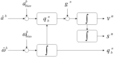
Figure 1: Strapdown mechanization
Figure 1 shows the integration of the IMU signals by means of the well known strapdown mechanization (Titterton and J.L.Weston, 2004). The superscriptsbandnare standing for body-frame and navigation-frame respectively. The navigation frame has an arbi-trary origin with its axes aligned to the local tangent plane. Some difficulties arise when integrating measured angular velocityωˆb and accelerationsaˆb. Besides systematic scaling errors and errors from axis-misalignment which can be corrected beforehand, the bias termsωbbias,a
b
biasare unknown from on to switch-on and also varying with temperature and time. This leads to a strong drift in attitudeqn
b, velocityvn, and positionsnif left un-compensated.
First, the quaternion update is calculated as follows:
qnb,tk+1 =q senting the rotation from body-frame to navigation-frame at time tk. The operator◦describes a quaternion multiplication. For the velocity update, the change in velocity is calculated from cor-rected acceleration measurementab= ˆab−abbiaswith
∆vb=abtk+1∆t+
and rotated to the navigation-frame with
Now it can be corrected for gravitationgand added to the previ-ous velocity.
vntk+1=v n
tk+ ∆vn+g∆t (4)
For the intervaltktotk+1the position integral is approximated
with the trapezoidal rule.
xntk+1=x A detailed derivation of the strapdown equations can be found in (Titterton and J.L.Weston, 2004). Since the used gyroscopes do not provide a sufficient accurate measurement to resolve the earth rotation it is not possible to find the north direction. Because there is also no global position reference available the earth rotation is neglected. For most indoor applications with low velocities and short times of pure inertial integration this is acceptable.
2.2 Stereo Vision
Visual information of a stereo system can be used for ego motion estimation or visual odometry (Olson et al., 2003, Nistér et al., 2004). Changes in position and attitude between two consecutive image pairs are estimated from homologous points. At a fixed frame rate this corresponds to measurements of velocity and an-gular velocity. To measure in images, a precise knowledge of ge-ometric camera calibration is assumed (Grießbach et al., 2008). In projective spacePmapping of a homogeneous object point
˜
M∈P3to an image pointm˜ ∈P2is defined with,
˜
m= PM˜ (6)
wherePis a 3×4-projection matrix (Hartley and Zisserman, 2000) consisting of the parameters of the interior- and exterior orienta-tion of the camera.
P = K
R|t
(7)
withR,tdescribing the rotational matrix and translation of the exterior orientation and the camera matrixKcontaining the focal lengthfand the principal pointu0, v0.
Furthermore lens distortion has to be considered. The very com-mon radial distortion model (Brown, 1971) is used, considering pincushion or barrel distortion which is expressed as follows:
wherex, yare normalized image coordinates calculated from the image coordinatesm˜ = (u, v,1)T
.
For image based pose estimation, features have to be detected and tracked over consecutive frames. Natural landmarks such as corners, isolated points or line endings are found by analysing the autocorrelation matrix from image intensity gradients as pro-posed by (Harris and Stephens, 1988).
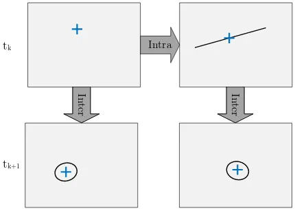
Intra
Figure 2: Paths for intra-frame and inter-frame matching
The extracted features have to be matched by using normalized cross correlation to find homologous image points. Figure 2 shows the two different matching steps. First, features in the left im-age at timetkare matched to the right image at timetk (intra-matching). By using the epipolar constraint, the search area is reduced to a single line. 3D object coordinates are now recon-structed by applying the interior orientation and the relative exte-rior orientation of the cameras.
The next step will be to match left and right images at timetk to left and right images at timetk+1 (inter-matching). Having
the strapdown navigation solution from inertial measurements, it is possible to predict the relative change in position and attitude
∆R′|∆t′
. With the triangulated object pointsM˜ the expected feature positionsm˜′at timet
k+1as well as their uncertainties are
calculated. The image point uncertainties are used to determine the size of the search area.
˜
With the found homologous image points, the relative change in pose between both image pairs can be estimated. This is done by minimizing the distance of image pointsm˜ from timetk+1to
transformed and back-projected object points from timetk.
min
∆R,∆tkK
∆R|∆t ˜
Mk−m˜k+1k2 (13)
2.3 Data Handling
The low-level sensor fusion is realized by a FPGA board that has different sets of Add-ons attached. Depending on the applica-tion, major interface standards of low bandwidth sensors like SPI, CAN, RS232, digital in/outputs are supported. The data sampling process of external sensors usually takes place asynchronous to the capturing device. This makes it difficult for multi-sensor sys-tems to align the different measurements to one common time line during the fusion process. The custom hardware used within the presented multi-sensor platform allows precise and determin-istic synchronization by referencing all sensor data to one local time scale that is kept by the FPGA. A high precision clock gener-ates timestamps to which all sensor communication is referenced.
The main objective for the data handling software is to set up a data processing chain from low level data to high level infor-mation (e.g. from sensor measurements to a navigation solution). Ideally, a particular task is encapsulated in a container, having only defined inputs and outputs. If input data is available, the task is immediately executed and sent to an output buffer. It is important to have buffer capabilities as a succeeding task may not be ready to receive new data at the moment when it is gener-ated. Combining those containers allows for a flexible, efficient data handling, and data processing. For a detailed description see (Grießbach et al., 2012)
Sensors Grabbing Middleware Application Network Trigger
IMU
Tilt Camera Camera
Camera Camera Stereo
Pose Estimation Trigger
IMU
Tilt
FPGA Switch
Stereo Matching
Strapdown Filter
Figure 3: Sensor data processing chain
2.4 Data Fusion
To combine the different sensor outputs to a navigation solution a derivative free Kalman filter is used. The main advantages of that filter type are the third order accuracy with Gaussian inputs and the easy integration of mostly nonlinear equations. The systems ego motion is modeled with the assumption of constant angular rate and acceleration over a discrete period of time. The filter was formulated in total state space with a 16 components state vectorsincluding the rotation in terms of a quaternion, velocity, raw angular velocity, angular velocity bias and acceleration bias, each vector with three degrees of freedom.
s=hqnb, v
n, ˆ
ωb, ωbbias, a b bias
i
(14)
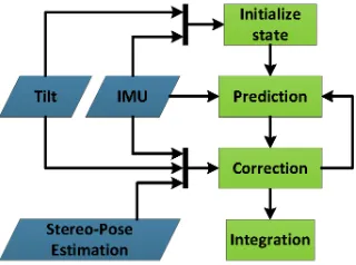
Figure 4 shows the combination of Kalman filter and optical sys-tem which provides incremental attitude- and position updates. Receiving IMU-, camera-, or inclinometer-measurements the fil-ter cycle is completed including a check for feasibility of the data. (Grießbach et al., 2010). The corresponding observation equa-tions for the visual data are defined as follows:
ˆ
ωbcam,tk = ωˆ
b
tk−ω
b
bias,tk+η (15)
0 ˆ
vbcam,tk
= qbn,tk◦
0
vn tk
◦qnb,tk+ζ, (16)
wherevˆb
cam,tk and ωˆbcam,tk denote the estimated velocity and
angular velocity of the visual measurement. The variables η, ζ describe their zero-mean Gaussian white noise sequences re-trieved from the estimation process.
Figure 4: Fusion filter flowchart
3 SENSOR HEAD
This chapter gives an overview of the applied sensors and their main characteristics. The default configuration consists of a micro-electromechanical IMU (MEMS) and two cameras forming a stereo system. Additionally an inclination sensor is added to get a more accurate system initialization. Other sensors capable of provid-ing position, attitude, or their derivatives, e.g. GPS receiver, or barometer may be included for redundancy and more accuracy. In case of bad light conditions two LED’s proving near infrared illumination are also included but not used for the indoor experi-ment.
Figure 5: IPS prototype
MEMS-Sensors have the advantage to be small, lightweight and low-cost in comparison to IMU’s with fibre-optical-gyros (FOG) or ring-laser-gyros (RLG). Although there is reasonable progress in the development of MEMS-gyros, FOG and RLG are still sev-eral orders in magnitude better with regard to bias stability and angle random walk (Schmidt, 2010). MEMS-gyros are also sen-sitive to accelerations introducing an additional error to the sys-tem. In fact, pure inertial navigation with MEMS-IMU’s will give very pure performance and can be used only for short periods of time. Table 1 shows the specification of the used IMU.
Gyro Acceleration
Range ±350◦/s ±18 g
Bandwidth 330 Hz 330 Hz
Bias stability 25.2◦/h 0.2 mg Scale-factor stability 10000 ppm 15000 ppm Random walk 2◦/√h 0.2 m/s/√h
Table 1: IMU ADIS-16405 specification
with reasonable uncertainties from triangulation. The images are binned by factor two to allow real-time data processing with 15 frames per second on a standard notebook. This includes image logging, real-time image processing, and data fusion.
Number of pixels 1360×1024 Frame rate ≤30 Hz, typ. 15 Hz Focal length 4.8 mm
Field of view 85◦×69◦
Table 2: Prosilica GC1380H specification
Additionally a two axis inclination sensor is used to give an ab-solute reference measurement to the local tangent plane which defines two axis of the local navigation frame.
Range ±90◦ Accuracy 0.1◦ Resolution 0.025◦
Table 3: Tilt ADIS-16209 specification
4 RESULTS
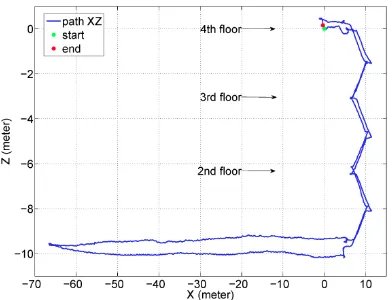
IPS was evaluated for accuracy, robustness, and repeatability in a common office environment. Lacking a ground truth, a closed loop scenario was chosen to evaluate the relative error in attitude and position. The run shown in figures 6, 7, and 8 has an absolute path length of 317 meters covering 4 floors. This includes the staircase, narrow corridors, and a wider entrance area with very different illumination and feature characteristics.
Figure 6: Path overview (xy-view)
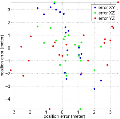
The run was repeated 21 times under real-life conditions, with normal walking speed at 1.5 m/s, during working hours with peo-ple interfering the visual measurement. To avoid systematic er-rors the system was carried by varying people and restarted after every trial. Figure 9 shows the distribution of the 2D position errors for each pair of axes. The translational errors are more or less evenly spread over all axes.
The averaged closed loop rotation and translation errors over all 21 trials are summarized in table 4. Due to the inclination sensor supporting the horizontal axes in times of hold-up, their errors
Figure 7: Path Overview (xz-view)
Figure 8: Path overview (yz-view)
matches the inclination sensor accuracy given in table 3. In com-parison, the unsupported yaw angle accumulates a much higher error. As table 4 indicates, an averaged absolute position error of 2.7 meter or 0.85% of the total path length is achieved.
Mean Error Standard Deviation
roll [deg] -0.1 0.3
pitch [deg] -0.1 0.2
yaw [deg] 5.5 14.5
x [m] 0.4 1.0
y [m] 0.5 2.2
z [m] -0.2 1.7
absolute error [m] 2.7 1.3
Table 4: Closed loop errors
This error is partly caused by phases where no or little features could be seen, resulting in missing or low quality vision data. The consequence is an increased error grow from integrating the IMU measurements. Such difficult situations occur through changing lighting conditions, a low texturing at some areas, or for example at narrow stairways with all objects to close for the stereo sys-tem. Another error source can be found by the IMU scale-factors which are greater than 1% of the specific range (see table 1).
4.1 3D Point Cloud Application
Figure 9: 2D position error of 21 runs for all pairs of axes
very powerful but time consuming method (Hirschmüller, 2005). To fulfil the real time requirements, the algorithm was imple-mented on a Graphical Processing Unit (Ernst and Hirschmüller, 2008).
In combination with the navigation solution, the 3D point cloud of each image pair is transformed to the navigation-frame and merged together to get a high density raw point cloud. Figure 10 shows an example point cloud. This process is carried out off-line without further data processing.
Figure 10: View of generated raw 3D point cloud
5 CONCLUSION
An integrated positioning system has been presented, including a hardware concept to guarantee synchronized sensor data as well as a software design for real time data handling and data pro-cessing. The software concept allows to partition the different tasks and helps to create a flexible and efficient data processing chain. An application of the framework is shown realising an indoor navigation task combining inertial and optical measure-ments. The complementary properties of both systems are used to reduce the drift of the inertial sensors and at the same time supporting the feature tracking with inertial information. The proposed system provides a robust solution for navigation tasks in difficult indoor environments, which was shown with multi-ple runs in a closed loop scenario. An absolute error of less than 1% of the absolute path length was achieved. This error is partly
caused by the insufficiently calibrated low cost IMU, introducing additional systematic errors. Future work will address this issue more deeply. Another step would be the integration of additional sensors, e.g. a barometer or a magnetometer.
It was shown that a high density point cloud can be generated combining the IPS trajectory with the 3D information produced by the SGM algorithm. Further steps would have to include a substantial data reduction.
REFERENCES
Brown, D., 1971. Close-Range Camera Calibration. Photogram-metric Engineering 37, pp. 855–866.
Ernst, I. and Hirschmüller, H., 2008. Mutual Information Based Semi-Global Stereo Matching on the GPU. In: ISVC ’08: Pro-ceedings of the 4th International Symposium on Advances in Vi-sual Computing, Springer-Verlag, Berlin, Heidelberg, pp. 228– 239.
Fischler, M. and Bolles, R., 1981. Random sample consensus: A paradigm for model tting with applications to image analysis and automated cartography. Communications of the ACM.
Grießbach, D., Bauer, M., Hermerschmidt, A., Krüger, S., Scheele, M. and Schischmanow, A., 2008. Geometrical camera calibration with diffractive optical elements. Opt. Express 16(25), pp. 20241–20248.
Grießbach, D., Baumbach, D. and Zuev, S., 2010. Vision Aided Inertial Navigation. In: International Calibration and Orientation Workshop , EuroCOW 2010, Vol. XXXVIII, ISPRS, Castellde-fels, Spain.
Grießbach, D., Baumbach, D., Börner, A., Buder, M., Ernst, I., Funk, E., Wohlfeil, J. and Zuev, S., 2012. IPS – A System for Real-Time Navigation and 3D-Modeling. ISPRS - International Archives of the Photogrammetry, Remote Sensing and Spatial In-formation Sciences XXXIX-B5, pp. 21–26.
Harris, C. and Stephens, M., 1988. A Combined Corner and Edge Detector. In: in Proc. of the 4th ALVEY Vision Conference, pp. 147–151.
Hartley, R. and Zisserman, A., 2000. Multiple View Geometry in Computer Vision. Cambridge University Press.
Hirschmüller, H., 2005. Accurate and Efficient Stereo Processing by Semi-Global Matching and Mutual Information. In: In Proc. CVRP, IEEE Computer Society, pp. 807–814.
Nistér, D., Naroditsky, O. and Bergen, J., 2004. Visual odometry. In: Computer Vision and Pattern Recognition, pp. 652–659.
Olson, C. F., Matthies, L. H., Schoppers, M. and Maimone, M. W., 2003. Rover Navigation Using Stereo Ego-Motion. Robotics and Autonomous Systems 43(4), pp. 215–229.
Schmidt, G. T., 2010. INS/GPS Technology Trends. In: RTO-EN-SET-116, Low-Cost Navigation Sensors and Integra-tion Technology.
Titterton, D. and J.L.Weston, 2004. Strapdown Inertial Naviga-tion Technology. Second edn, MIT Lincoln Laboratory.