PERSPECTIVE INTENSITY IMAGES FOR CO-REGISTRATION OF TERRESTRIAL
LASER SCANNER AND DIGITAL CAMERA
Yubin Liang a, b,*, Yan Qiu a, b, Tiejun Cui a, b
a
College of Urban and Environmental Sciences, Tianjin Normal University, Tianjin 300387, China
b Tianjin Engineering Center for Geospatial Information Technology, Tianjin Normal University, Tianjin 300387, China
Commission III, WG III/2
KEY WORDS: Point Cloud, Perspective Intensity Image, Image Matching, Random Sample Consensus (RANSAC), Pose Estimation, Terrestrial Laser Scanning (TLS)
ABSTRACT:
Co-registration of terrestrial laser scanner and digital camera has been an important topic of research, since reconstruction of visually appealing and measurable models of the scanned objects can be achieved by using both point clouds and digital images. This paper presents an approach for co-registration of terrestrial laser scanner and digital camera. A perspective intensity image of the point cloud is firstly generated by using the collinearity equation. Then corner points are extracted from the generated perspective intensity image and the camera image. The fundamental matrix F is then estimated using several interactively selected tie points and used to obtain more matches with RANSAC. The 3D coordinates of all the matched tie points are directly obtained or estimated using the least squares method. The robustness and effectiveness of the presented methodology is demonstrated by the experimental results. Methods presented in this work may also be used for automatic registration of terrestrial laser scanning point clouds.
* Corresponding author
1. INTRODUTION
Terrestrial laser scanning has been widely used in many areas such as building reconstruction, virtual reality, archaeology, and industrial applications for three dimensional measurement, modelling and visualization of real world scenes. Accurate 3D point clouds and true-color images of the scanning scene can be acquired by using terrestrial laser scanners and digital cameras. These two complementary datasets can be geometrically registered and then used to reconstruct visually appealing and measurable models of the scanned objects. Nowadays a digital camera can be mounted on a terrestrial laser scanner to acquire images of the scanning area. However, the mounted camera is often equipped with a fixed-focal-length lens. And the acquired images are often out of focus due to varying distance from objects to the camera. Another problem is that the laser scanner and the mounted digital camera have different field of view, which makes the imaged area and scanned area not completely overlapped. Therefore co-registration of point clouds with images acquired by cameras that can be moved at will becomes an important topic of research.
Many approaches have been reported to co-register laser scanning point clouds and optical images. The registration procedure mainly consists of feature extraction, feature matching and solution of orientation parameters. Feature point extraction from images has been well studied in the past several decades. Feature points extracted from images are usually better located and more robust for matching. Therefore, many researchers apply feature point extraction and robust matching techniques to co-registration of laser scanning point clouds and optical images. Dias et al. (2002) proposed a co-registration approach based on matching of camera images with panoramic intensity images. The Harris corner proposed by Harris and
Stephens (1988) was used for corner extraction. Then the extracted corners were matched using cross correlation within a given search window. The camera poses were finally solved through a camera calibration procedure. Forkuo and King (2004) presented a co-registration method that was based on matching of an optical image with perspective intensity image. The perspective intensity image was generated by perspective projection of the point cloud and the greyscal value of the synthetic image was evaluated using scaled intensity of the scanning points. The Harris corner detector was used to detect and extract corners in both optical image and perspective intensity image. The matched corners were refined with spatial resection under RANSAC framework (Fischler and Bolles, 1981). Feature point extraction and matching are important to achieve satisfactory results for this kind of co-registration methods. González-Aguilera et al. (2009) co-registered point cloud with camera image by matching a camera image with a range image obtained from the terrestrial laser scanner. Feature points were firstly extracted using the Förstner operator (Förstner and Gülch, 1987), and then a robust matching procedure was applied to remove the outliers in the resulting matches. Spatial resection was finally used in a RANSAC iteration to solve the pose of the camera image.
The SIFT operator proposed by Lowe (2004) is widely used for automatic matching images with large rotation, scale and lighting variance (Snavely et al., 2006; Agarwal et al., 2011). Therefore, many researchers applied SIFT-like operators to matching optical images with perspective intensity images. Meierhold et al. (2010) used the SIFT operator to detect corresponding points in the camera image and a perspective intensity image. Fundamental matrix with RANSAC was used to remove outliers from initial matches. Although in many cases using SIFT with default parameters brings satisfactory matching
results, there are situations where it does not necessarily provide enough candidate feature points. So for matching datasets acquired with different types of sensors, modifications of SIFT parameters have been proposed to increase the number of matched points. Sima and Buckley (2013) presented a method for matching of short wave infrared and visible wavelength images using optimized SIFT. Experiments showed that the number of scales in an octave had the strongest influence on the matching results. However, the number of points matched per single hyperspectral band was largely dependent on the band wavelength.
Although feature point extractors and descriptors have been used for automatic matching multimodal images, reliable feature point extraction and matching for co-registration of point clouds and digital cameras remains difficult mainly because the visual appearance of the datasets acquired with different types of sensors vary dramatically. Furthermore, as pointed by Meierhold et al. (2010), accurate orientation result may be unachievable due to falsely matched feature points. Therefore, certain level of intervention often leads to more robust results.
This paper presents an approach for co-registration of terrestrial laser scanner and digital camera. A perspective intensity image of the scanning area is firstly generated from the point cloud by using the collinearity equation. Then corner points are extracted from both the generated perspective intensity image and the camera image. Matching of corner points extracted from the perspective intensity image and the digital image is carried in an interactive way to improve reliability and accuracy of the image matching procedure. Then the 3D positions of matched corners are determined. Pose estimation is carried under the RANSAC framework to finally co-register the terrestrial laser scanner and the digital camera. Section 2 of the paper details the methodology of the co-registration. Experimental results are discussed in Section 3 and conclusion is made in Section 4.
2. METHODOLOGY
The presented methodology consists of three consecutive parts: generation of perspective intensity image, feature point extraction and robust matching, and absolute orientation of the camera image.
2.1 Generation of a perspective intensity image
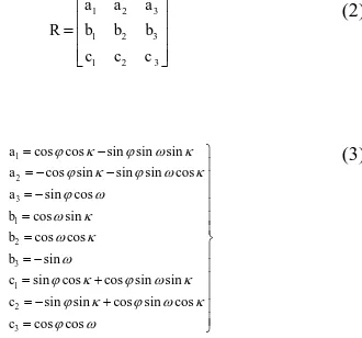
A perspective intensity image is firstly generated and used for interactive determination of tie points between the point cloud and the optical image. To generate a perspective intensity image, projection models from the photogrammetry or computer vision community can be used. In this work, the collinearity equation is used to generate the perspective intensity image. The collinearity equation is a mathematical model which defines the relationship of a three dimensional point P and its perspective projection p (Wang, 2007). Figure 1 depicts the geometric structure of perspective projection defined by the collinearity equation (equation (1)).
Figure 1. Geometric structure of perspective projection defined by the collinearity equation the object coordinate system, f is the focal length, and the nine parameters (a1-c3) are the elements of the three dimensional rotation matrix R which defines the orientation of the principal axis as rotation about the Z-axis. Generally, the three dimensional coordinates of a terrestrial laser scanning point is defined under the scanner’s own coordinate system. A terrestrial laser scanner usually rotates 360°horizontally and records position and
reflectance of each sample point that is visible in the scanner’s field of view. Given a point cloud and assuming all of the parameters in equations (1)-(3) are known, the algorithm to generate a perspective intensity image is described in Algorithm 1.
Algorithm 1
Input: A point cloud data pcd; imaging parameters (ip) including pixel size d, sensor width, aspect ratio and angle of view and the interior and exterior orientation parameters. for i = 1:sizeof(pcd)
if vis(pcd(i), ip) = = true prj(pcd(i), pii); end for
pii = postpro(pii);
Output: The generated perspective intensity image pii.
In the pseudocode above, vis(.) determines the visibility of a point pcd(i) with respect to the perspective intensity image, and prj(.) projects a 3D point onto the perspective intensity image pii using the collinearity equation. vis(.) first determines if the line segment connecting the center of projection and a 3D point pcd(i) intersects the image plane by line-plane intersection test. Then the function determines whether the projection of the 3D point is within the range of the image. If a 3D point passes both tests, then it is visible to the perspective intensity image. After nearest interpolation, gamma correction and greyscale adjustment implemented in the postprocessing function postpro(.) , the generated perspective intensity image is output.
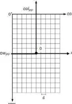
Figure 2. Image plane coordinate system and pixel coordinate system
As mentioned above, (x, y) in equation (1) is the planar position of perspective projection of P under image plane coordinate system O-xy. Figure 2 shows the relationship between the image plane coordinate system O-xy and the pixel coordinate system O’-colrow. The position of p under coordinate system O’-colrow can be calculated by equation (4).
pp
where (colpp, rowpp) is the position of the principal point under coordinate system O’-colrow, (x, y) is the position of p under coordinate system O-xy, d is the pixel size. Therefore, (col, row) can be obtained by rounding the right parts of the equations to integers.
2.2 Feature point extraction and robust matching
In the presented method, corner points are extracted from both the generated perspective intensity image and the camera image using algorithm developed by Shi and Tomasi (1994). The corner extractor directly computes minimum eigenvalue of structure tensor of the weighted sum of squared differences (SSD) between two image patches. After the corner point extraction process, tie points are interactively determined from the extracted corners.
It is well known that the projections of the same 3D point on different images satisfy the epipolar geometry (Hartley and Zisserman, 2004). The epipolar geometry is often represented by the fundamental matrix F (equation (5)).
2 1
0
extracted from the perspective intensity images and the camera image. The fundamental matrix F is firstly solved using theinteractively selected tie points and then used to obtain more matches between corners extracted from the perspective intensity image and the camera image.
All the pairs of corners including the interactively selected and newly matched ones are used to solve the fundamental matrix F under the RANSAC framework. The matching procedure is described in Algorithm 2.
Algorithm 2
Input: Corners {cci} extracted from the camera image, corners {cii} extracted from the intensity image, interactively selected tie points {itp}, the geometric error threshold Tsh, and the number of samples nsmp for RANSAC.
Initialize: Initial tie points set {tp}←Φ, robustly matched tie
Output: Robustly matched tie points set {rtp}
In the pseudocode above, ranfund(.) estimates the fundamental matrix F is using the interactively selected tie points under the RANSAC framework. Corners extracted from the camera image are traversed and matched against that extracted from the intensity image using the estimated F. If the geometric error (Sampson distance) between a pair of two corners is smaller than a given threshold Tsh, it is considered as a matched pair. After a refinement procedure with RANSAC, the robustly matched tie points set {rtp} is output.
2.3 Absolute orientation of the camera image
To determine the absolute orientation parameters of a camera image, the 3D positions of the tie points have to be obtained first. The perspective intensity image is generated directly from the point cloud by using the collinearity equation, therefore coordinates of its 3 by 3 neighbours are firstly used to estimate
a local plane in three-dimensional space. Then these 3D points are orthoprojected onto the estimated plane. The three dimensional coordinates of the tie point are finally estimated using the least squares method as detailed in (Liang et al., 2014).
EPnP proposed by Lepetit et al. (2008) is used to estimate the pose of the camera image. The absolute orientation parameters can be estimated using all of the matched tie points. But if a pair of the tie points does not correspond to the same point in the object space, it will lead to errors in the pose estimation. To improve the robustness and accuracy of the pose estimation process, the RANSAC framework is used to remove outliers.
3. RESULTS AND DISCUSSION
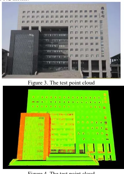
The presented methodology is test with a camera image (Figure 3) and a point cloud (Figure 4) of the library building of the university. The photo is taken with a NIKON D300S camera. The resolution of the photo is 4288 by 2848 and the focal length is 32mm. The point cloud is acquired using a RIEGL VZ-1000 laser scanner. The angle resolutions in the horizontal and vertical direction are set to 0.008°respectively. The point
cloud consists of 18,032,611 valid points. The height of the library building is about 58 meters. The horizontal distance between the facade of the library building and the scanner is about 102 meters.
Figure 3. The test point cloud
.
Figure 4. The test point cloud
The perspective center of the intensity image is set to the origin of the scanner’s own coordinate system as (0, 0, 0). The azimuth and altitude of the principal axis is set to 180°and
20°respectively. The imaging parameters are set as follows:
aspect ratio = 3/4, focal length f = 20 mm, pixel size d = 3 μm, sensor width = 20.48 mm. The position of the principal point under pixel coordinate system is set to center of the image. The dimension of the generated intensity images is therefore 6827 by 5120. The experiments are carried out on a Dell E6440 with 8GB main memory and 64-bit Win 7 operating system. The algorithms are implemented in Matlab scripts. Higher resolutions may lead to “holes” in the intensity image (Figure 5). To filling the holes, greyscale values of these pixels are
interpolated using the intensity of their nearest neighbors (Figure 6). If several neighboring 3D points are projected to the same pixel of the intensity image, only the point that is nearest to the center of projection is considered. Then gamma correction is carried (Figure 7) and greyscale of the intensity image is readjusted to enhance the contrast of the image (Figure 8). It can be seen that the generated intensity image is clear and complete and building structures in the scanning scene are well distinguishable.
Figure 5. Perspective intensity images: original image
Figure 6. After nearest neighbor interpolation with a 3 by 3 window
Figure 7. Gamma correction
Figure 8. After greyscale adjustment
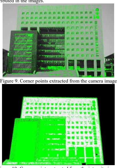
16,675 and 109,527 corner points are extracted from the camera image and intensity image respectively (Figure 9-10). It can be
seen that the corner points are densely extracted and evenly distributed in the images.
Figure 9. Corner points extracted from the camera image
Figure 10. Corner points extracted from the intensity image 11 pairs of corner points that distribute evenly in the scanned scene are interactively selected from the intensity image and the camera image as initial tie points. The fundamental matrix F is estimated using these 11 initial tie points with RANSAC and another 32 corners are matched with the estimated F. The geometric error threshold Tsh is set to 0.001. Assuming the ratio of outliers in the matched tie points is 20%, accurate refinement can be obtained after 26 samplings (nsamp=26) with a probability larger than 99%. The reprojection error (RMSE) of the pose estimation is 2.8 pixels.
To make a comparison, 10 pairs of tie points are selected directly from the point cloud and the camera image. After pose estimation with EPnP, a reprojection error of 4.1 pixels is achieved. Pose estimation using the presented approach is more accurate than using tie points directly selected from the point cloud. The more accurate result is guaranteed by two procedures: firstly, the feature points are more salient on the continuous intensity image than that in the discrete point cloud. Secondly, the estimated 3D positions of the extracted feature points are usually more accurate than the directly selected 3D points, especially when the point density of the scanned object is low.
The estimated pose is used to project the laser scanning points onto the camera image and the point cloud with RGB color is shown in Figure 11-13. It can be seen that the positions of the laser scanning points and their RGB colors are closely matched. The point cloud rendered with RGB clolors is visually more intuitive than the point cloud rendered with intensity.
Figure 11. The point cloud with RGB color
Figure 12. The point cloud from a close and look up viewpoint
Figure 13. A closeup of the facade
4. CONCLUSIONS AND FUTURE WORK
A methodology for semi-automatic co-registration of terrestrial laser scanner and digital camera is presented in this paper. A perspective intensity image of the point cloud is firstly generated. Several corner points extracted from the generated perspective intensity image and the camera image are then interactively selected as tie points. The fundamental matrix F is estimated using the selected tie points and used to obtain more matches. The 3D coordinates of all the matched tie points are directly obtained or estimated using the least squares method. RANSAC is used to remove outliers in the matches, which improves the robustness and accuracy of the co-registration procedure. The robustness and effectiveness of the presented methodology is demonstrated by the experimental results. The presented co-registration method does not require real-time rendering of large scale point cloud, therefore makes it possible to co-register large scale point clouds with camera images on computers which are not equipped with high performance graphics hardware. Methods presented in this work may also be used for automatic registration of terrestrial laser scanning point clouds.
Acknowledgment
This work is supported by the Doctoral Fund of Tianjin Normal University under Grant 52XB1306, Municipal Key Laboratory
Open Fund of Tianjin Normal University under Grant YF11700103, and Tianjin Science and Technology Planning Project under Grant 14TXGCCX00015.
References
Agarwal, S., Furukawa, Y., Snavely, N., Simon, I., Curless, B., Seitz, S. M., and Szeliski, R., 2011. Building rome in a day. Communications of the ACM, 54(10), pp. 105-112.
Dias, P., Sequeira, V., Gonçalves, J. G., and Vaz, F., 2002. Automatic registration of laser reflectance and colour intensity images for 3D reconstruction. Robotics and Autonomous Systems, 39(3), pp. 157-168.
Förstner, W., and Gülch, E., 1987. A fast operator for detection and precise location of distinct points, corners and centres of circular features. Paper presented at the Proc. ISPRS intercommission conference on fast processing of photogrammetric data, pp. 281-305.
Fischler, M. A., and Bolles, R. C., 1981. Random sample consensus: a paradigm for model fitting with applications to image analysis and automated cartography. Communications of the ACM, 24(6), pp. 381-395.
Forkuo, E.; King, B., 2004. Automatic fusion of photogrammetric imagery and laser scanner point clouds. In: The International Archives of the Photogrammetry, Remote Sensing and Spatial Information Sciences, Istanbul, Turkey, 12-23 July, 35(B4), pp. 921-926.
González-Aguilera, D., Rodríguez-Gonzálvez, P., and Gómez-Lahoz, J., 2009. An automatic procedure for co-registration of terrestrial laser scanners and digital cameras. ISPRS Journal of Photogrammetry and Remote Sensing, 64(3), pp. 308-316.
Harris, C., and Stephens, M., 1988. A combined corner and edge detector. Alvey Vision Conference, Vol. 15, pp. 147-151.
Hartley, R., and Zisserman, A., 2004. Multiple View Geometry in Computer Vision. Cambridge University Press, Cambridge, pp. 239-247.
Lepetit, V., Moreno-Noguer, F., and Fua, P., 2009. Epnp: An accurate o (n) solution to the pnp problem. International Journal of Computer Vision, 81(2), pp. 155-166.
Liang, Y.-B., Zhan, Q.-M., Che, E.-Z., Chen, M.-W., Zhang, D.-L., 2014. Automatic registration of terrestrial laser scanning data using precisely located artificial planar targets. IEEE Geoscience and Remote Sensing Letters, 11(1), pp. 69-73.
Lowe, D., 2004. Distinctive image features from scale-invariant keypoints. International Journal of Computer Vision, 60(2), pp. 91-110.
Meierhold, N., Spehr, M., Schilling, A., Gumhold, S., and Maas, H., 2010. Automatic feature matching between digital images and 2D representations of a 3D laser scanner point cloud. In: The International Archives of the Photogrammetry, Remote Sensing and Spatial Information Sciences, Vol. 38, pp. 446-451.
Shi, J., and Tomasi, C., 1994. Good features to track. Paper presented at the Computer Vision and Pattern Recognition, 1994. Proceedings CVPR '94., 1994 IEEE Computer Society Conference on, pp. 593-600.
Sima, A. A., and Buckley, S. J., 2013. Optimizing SIFT for matching of short wave infrared and visible wavelength images. Remote Sensing, 5(5), pp. 2037-2056.
Snavely, N., Seitz, S. M., and Szeliski, R., 2006. Photo tourism: exploring photo collections in 3D. ACM Transactions on Graphics, 25(3), pp. 835-846.
Wang, Z., 2007. Principle of Photogrammetry. Wuhan University Press, Wuhan, pp. 1-13.