ABOUT THE USED OF NEURAL NETWORKS IN INTEGRATED NUMERICAL CIRCUITS AND SYSTEMS
by
Remus Joldeş, Ioan Ileană, Emil Olteanu
Abstract. The paper presents main aspects regarding the use of neural networks in integrated numerical circuits and systems viewed as finite state systems FSS. Beyond the theoretical aspects as concerns the use of neural networks in numerical systems, a method having the role of design guide is also presented for the design and achievement of such FSS, in this new approach.
Keywords: neural networks, finite state systems, design methods for finite state systems, simulation using neural networks.
I. Premises
The issue of digital circuits and systems is generally treated by the general theory of finite state systems (FSS). Based on this theory we will treat the numerical integrated circuits and systems by using neural networks for their simulation.
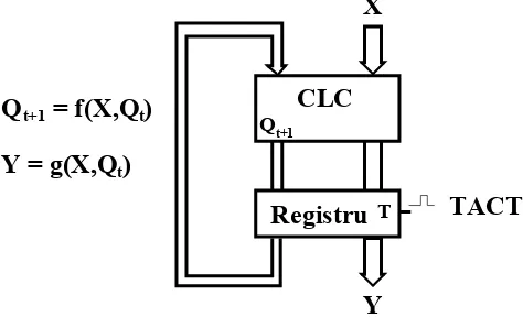
All types of numerical systems can be obtained from the sequential logic system presented in Figure 1.
Registru
Qt+1
T
CLC
X
Y
Q
t+1= f(X,Q
t)
Y = g(X,Q
t)
[image:1.595.185.422.359.503.2]TACT
Figure 1. Squential logic system
The functional behavior of this sequential logic system can be described by two functions f and g, named characteristic functions. These functions show the evolution of Y outputs and the states of the system Q at the t+1 moment, depending on the system’s state at the moment t and the system’s inputs X.
theoretical nuances and/or practical approach). By using neural networks in the study of such systems, the combinative hazard is actually excluded. The behavior of the combinative logic circuit CLC is not time depending and it can be described by Boolean functions or binary algebra functions.
Boolean function can be explicitly expressed by logic tables of truth canonical forms S or P, Veitch-Karnaugh diagrams, Quinne Mc Cluskey etc. The most difficult problem in the classical paradigm of this systems’ approach is the minimization of the electronic system for the implementation of the given system, minimization which means to find the minimum functional system equivalent with the given one. In the case of the approach by neural paradigm the problem of minimization is implicitly solved by the conceptual philosophy of the neural networks, itself.
In the classical paradigm applied to the approach of these systems the following minimization methods are used:
• Analytical method by using theorems of the Boolean algebra, starting from the logic expression of the characteristic functions and application of the Boolean theorems until the minimized forms are obtained;
• Reduction of the system’s state space by the partitioning of space into equivalence classes;
• Minimization of the combinative logic circuit associated to the system by one of the graphical methods of the Veitch-Karnaugh or Quinne Mc Cluskey diagrams.
In the classical paradigm of these circuits’ approach, starting from the general theory of the finite state systems FSS, the mathematical modeling conducts to:
• Classification of the digital systems;
• Mathematical description of the digital systems’ behavior; • Establishment of the general design methods.
In general, any FSS can be mathematically decrypted by a quintuple like:
)
g
,
f
,
Q
,
Y
,
X
(
S
=
where:
•
X
{
x
1,
x
2,...,
x
p}
- represents the set of input variables in the FSS ; •Y
{
y
1,
y
2,...,
y
m}
- represents the set of output variables of the FSS; •Q
{
q
1,
q
2,...,
q
n}
- represents the set of states of the FSS;•
f
:
XxQ
→
Q
- represents the transition function of the states, this function defines the modifying process of the states in a FSS, being dependent on the inputs and the system’s former state;that is:
g
:
Q
→
Y
. There is a rigorously, mathematically demonstrated theorem which says that the two models (Mealy şi Moore) are equivalent. The system described by this quintuple is manned with finite states whilst X, Y and Q are finite therefore discrete. The realm of time which doesn’t explicitly appear in the definition is also formed by the se of integer numbersT
{
t
1,
t
2,...,
t
N+1}
where:t
1=
0
,t
2=
1
,t
3=
2
, …,t
N+1=
N
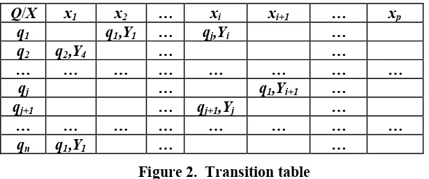
and which correspond to the appearance of synchronizations impulses of the tact generator. The characteristic functions f and g define the evolution of the FSS in time. These functions are represented by: transition tables, transition graphs and flow charts. Transition tables contain input variables in columns and components of the state matrix in lines. At the intersection of each column and line, the state and the next output are written, that is the value of function f and the value of function g separated by a comma, as in Figure 2.Using these transition tables the transition graphs and the evolution flow charts of the FSS can be drawn. FSS are completely described by these transition tables. In the case of the transition graphs,
q
1,
q
2,...,
q
n states will represent the nodes of the transition graph and the xi, Yj tupleswill represent the graph’s archesand the state variables which will change the system’s state.Q/X x1 x2 … xi xi+1 … xp
q1 q1,Y1 … qj,Yi …
q2 q2,Y4 … …
… … … … … … … …
qj … q1,Yi+1 …
qj+1 … qj+1,Yj …
… … … … … … … …
[image:3.595.153.460.335.463.2]qn q1,Y1 … …
Figure 2. Transition table
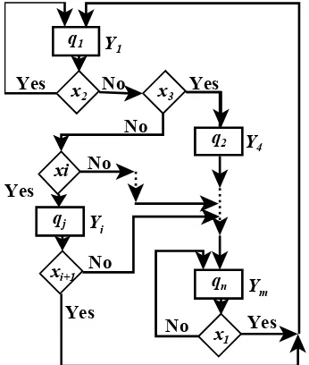
In this way the transition graphs contain the states of the FSS in nodes and the arches represent the determinations of inputs and outputs as in Figure 3. For example, if S system is in q1 state and the x2 input has been applied, system S remains in the same state, if xi input has been applied the system S passes into state qjand if x3 input has been applied the system passes in state q3, state q1 is reached when the system is in state qn and the applied input is x1 , etc.
q
jq
nq
2q
1x
i,Y
ix
i+1,Y
1x
1,Y
1x
2,Y
1 [image:4.595.212.408.76.221.2]x
1,Y
4x
3,Y
3Figure 3. Transition graph of a FSS
The classical paradigm of the approach of the FSS shows that such a system can be mathematically described by:
)
M
,
Y
,
X
(
S
=
where:
•
X
- represents the input space of the system; •Y
- represents the output space of the system;•
M
:
X
→
Y
- represents the input-output function of the system (in case of electronic systems, function M is explicitly expressed by the wave forms obtained by oscillography).q2
x3
x1
qn Ym
No Yes
Yes
xi+1 qj Yi
No
Yes
xi q1
Y4 No
No No
x2 Yes
Yes
Y1
[image:4.595.226.399.386.590.2]The definition by quintuple is extremely useful in the analyses and synthesis of systems, and the definition by triplets in experiments and system diagnosis.
II. Simulation of numerical systems by using neural networks
Due to the perfect functional similitude between neural networks of feed-forward type and numerical systems we shall see if it is possible to simulate numerical circuits and systems by using neural networks. Based on our research and the studied bibliography we have concluded that the fact is completely achievable. For the general case we propose the following simulating network of the integrated numerical circuits and systems:
Y
X
Tact
Retea neuronala feed-forward(cu 3 straturi) totalconectata
Figure 5. Neural network for the simulation of numerical circuits and systems
The neural networks inputs are represented by the set of input variables in system FSS
X
{
x
1,
x
2,...,
x
p}
and by the Tact. The presence of the tact signal is absolutely required for the synchronization of the stimulated system’s state change. The neural networks outputs are represented by the set of output variables of the FSS, that isY
{
y
1,
y
2,...,
y
m}
. For the network’s training, specialized software, known in the literature, can be used, software which doesn’t occur any problem in exploitation.After the network has been well trained and checked the next phase is the hardware implementation and testing in the new functional conditions. As regards the steps of design we propose the following design method:
• Step 1: Establishment of the truth table for the description of the FSS functioning and graphical achievement of the transition flow chart of system’s states.
• Step 2: Selection of the neural network of feed-forward type, totally connected, with 3 layers, establishment of neurons in the input layer, output layer and the hidden layer. The number of neurons in the input player has to be equal with p+1 (
x
1,
x
2,...,
x
pand tact), in the output layer should be m (y
1,
y
2,...,
y
m), and for the hidden layer we have concluded that the number is given by the relationship: (p+m+1)*2/3.• Step 4: Checking of the correct functioning of the obtained network. Checking should be done as regards correct functioning, speed and tolerance at the breaking of a bound. If problems occur, the number of neurons in the hidden layer should be changed (increased or decreased) and step 3 should be redone.
• Step 5: Hardware implementation of the neural network which stimulates the FSS.
III. Conclusions
We consider that due to the advantages of the neural networks, more and more electronic circuits, which are classically treated, can have neural implementations, which are simpler and more reliable. This approach can conduct to the achievement of complex neural finite state automates, as first stage in the achievement of neural computing systems.
References
1. DUMITRAŞ ADRIANA: Proiectarea reţelelor neuronale artificiale, Bucureşti, Casa editorial Odeon, 1997.
2. DUMITRESCU D., COSTIN HARITON: Retele neuronale, teorie si aplicatii, Bucuresti, Editura Teora, 1996.
3. KHALID MARZUKI, OMATU SIGEM, YUSOF RUBRYAT: Temperature Regulation with Neural Network and Alternative Control Schemes, I. E. E. E. Transactions on Neural Networks, vol. 6, No. 3, May 1995.
4. NERRAND O., ROUSSEL-RAGOT P., URBANI D., PERNNAZ L., DREYFUS G.: Training Recurrent Neural Networks: Why and How? An Illustration in Dynamical Process Modeling, I. E. E. E. Transactions on Neural Networks, vol. 5, No. 2, March 1994.
5. PARK YOUNG-MOON, CHOI MYEON-SONG, LEE KWANG Y.: An Optimal Tracking Neuro-Controller for Nonlinear Dynamic Systems, IEEE Transactions on Neural Network Vol.7, No. 5, September 1996, p. 1099-1110.
6. SASTRY P. S., SANTHARAM G., UNNIKRISHNAN K. P.: Memory Neural networks for Identification and Control of Dynamics Systems, I. E. E. E. Transactions on Neural Networks, vol. 5. No. 2, March 1994, p. 306-311. 7. JOLDEŞ R., ILEAN I., ROTAR C.: Utilization of neural networks in the
simulation of combinational logical circuits, Acta Universitatis Apulensis, Mathematics-Informatics, Alba Iulia, No. 3, 2002, p. 65-68.