PALMPRINT FEATURE REPRESENTATION
USING FRACTAL CHARACTERISTICS
DARMA PUTRA
Departement of Electrical Engineering and Information Technology, Faculty of Engineering,
Udayana University, Bali - Indonesia
E-mail: [email protected]
ABSTRACT
This paper introduced some new techniques to extract the palmprint features based on fractal codes and fractal dimension. Four new techniques based on fractal, namely FDFC (fractal dimension from fractal codes), FDIFC (fractal dimension image from fractal code), DIFC (distance image from fractal code), and AIFC (Angle image from fractal code) are proposed.. The main idea of these methods is the forming palmprint image representation by using fractal code parameters. There are three parameters of fractal codes are used namely position of range block, position of domain block, and size of range block. Those methods have been applied for palmprint verification system. The system has been tested by using database of 1050 palmprint images, are generated from 5 samples from each of the 210 persons randomly selected. Experiment results show that our proposed methods can achieve an acceptable accuracy rate.
Keywords: Biometrics, Fractal Codes, Fractal Dimension, Feature Extraction, Palmprint Recognition.
1. INTRODUCTION
Palmprint is the relatively new in physiological biometrics. In the palmprint, some kinds of features could be listed as geometry features (e.g., width, length, and area of a palm), palm line features (e.g., principal lines and wrinkles), and points features (e.g., minutiae and delta points)[13]. A palm lines have several advantages compared to other available features: low-resolution images can be used, low cost capture devices can be used, it is very difficult or impossible to fake palmprint, and their characteristics are stable and unique [9].
The main problem in palmprint recognition system is how to extract the palmprint features. Recently, many verification or identification technologies using palmprint biometrics have been developed. Zhang et al. [1], Darma Putra et al [4][6] applied 2-D Gabor filter to obtain the texture features of palmprints. Pang at al. [11] used the pseudo-orthogonal moments to extract the features of palmprint. LI et al. [12] transformed the palmprint from spatial to frequency domain using Fourier transform and then computed ring and sector energy features. Connie at al.[15] extracted the texture feature of palmprint using PCA and ICA. Wu et al.[9] extracted line feature
vectors (LFV) using the magnitudes and
orientations of the gradient of the points on
palm-lines. Kumar et al.[14] combined the palmprints and hand geometries for verification system. Each palmprint was divided into overlapping blocks and the standard deviation value of each block was used to form the feature vector.
In this paper, we introduce some new techniques to extract the features of palmprint based on fractal codes and fractal dimension. The structures of palm lines are natural and irregular, while fractal is good tools for the natural and irregular problems model. That is the reason why fractal is used to extract the palmprint features. There are four new methods are proposed namely, FDFC, FDIFC, DIFC, and AIFC.
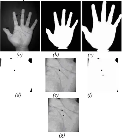
All of palm images are used in this paper are captured using Sony DSC P72 digital camera with resolution of 640 x 480 pixels. Each person was requested to put his/her left hand palm down on with a black background. There are some pegs on the board to control the hand oriented, translation, and stretching. ROI of palm images with 128x128 pixel are extracted automatically by using two steps in center of mass method that used in [4][6]. A sample of the hand and pegs position on the black board and ROI extraction steps are shown on Figure 1
features based on fractal. The palmprint feature matching is described in section 4. Section 5 reports our experimental results for both verification and identification. Finally, the conclusion and future work are presented in section 6.
(a) (b) (c)
(d) (e) (f)
(g)
Figure 1: Extraction of palmprint, (a) original image, (b) binary image of (a), (c) object bounded, (d) and (e) position of the first centroid mass in segmented binary and gray level image, respectively, (f) and (g) position of
the second centroid mass in segmented binary and gray level image, respectively.
2. FRACTAL CHARACTERISTICS
Self-similarity and fractal dimension are two main characteristics of fractal. These characteristics become the foundation of the proposed feature extraction methods in this paper. This section describes these characteristics.
2.1 Self-Similarity
This characteristic usually is used to produce the fractal codes of image. Fractal codes of images are obtained using the partitioned iterated function system (PIFS) method. PIFS method has become the foundation of present fractal image coding. This method works based on local self-similarity of image. In PIFS method, each image is partitioned into its range blocks and domain blocks. The size of the domain blocks is usually larger than the size of the range blocks. We applied quadtree partition technique to divide the image into domain and range blocks. The relation between a pair of
range block (Ri) and domain block (Di) is noted as
( )
i ii w D
R = (1)
wi is contracted mapping that describes the
similarity relation between Ri and Di, and is usually
defined as an affine transformation as bellow:
+
=
i i i i i i i i i i i i i i io
f
e
z
y
x
s
d
c
b
a
z
y
x
w
0
0
0
0
(2)where xi and yi represent top-left coordinate of the
Ri , and zi is the brightness value of its block.
Matrix elements ai, bi, ci, and di, are the
parameters of spatial rotations and flips of Di, si is
the contrast scaling and oi is the luminance offset.
Vector elements ei and fi are offset value of space.
We used the size of domain region twice the range size, so the values of ai, bi, ci, and di are 0.5. The
actual fractal code fi bellow is usually used in
practice[3].
(
) (
)
(
D D R R i i i i)
i
x
y
x
y
size
s
o
f
i i i
i
,
,
,
,
,
θ
,
,
=
(3)where
(
)
i
i R
R y
x , and
(
)
i
i D
D y
x , represent top-left
coordinate position of the range block and domain block, respectively, size is the size of range block,
and
θ
i represent the index of the spatial rotation ofthe domain region that have values: 0 (no transformation), 1 (reflection in the y axis), 2
(reflection in the x axis), 3 (180o rotation), 4
(reflection in the line y = x), 5 (rotate 90o
counter-clockwise), 6 (rotate 90o clockwise), and 7
(reflection in the line y = -x). The fractal codes of a palmprint image is denoted as follow:
N i if
F
1 ==
(4)where N represents the number of the fractal code. The inequality expression bellow is used to indicate weather the range and the relevant domain block is similar or not.
( )
R,D ≤ε,d (5)
where d(R,D) represents distance (RMSE) value
between range and domain block, and є is the
tolerance value. The range and the relevant domain
block is similar if d(R,D) is less or equal than є.
Otherwise, the block is regarded not similar.
The fractal dimension is computed by using the box counting method as bellow [8].
( )
s log( )
N( )
s log(s)D = (6)
where N(s) represents number of boxes with size s that containing any pixels object. The number of N(s) depends on the choice of s. The value of s is
changed from 1 to 2k pixels and counted the
corresponding number N(s), where k = 0, 1,
2,…and 2k < image size. The diagram log(N(s)) (as
y axis) and log(s) (as x axis) is plotted. A straight line is then fitted to the plotted line in the diagram and the slope of the line is denoted as dimension fractal of the object.
3. PALMPRINT FEATURE REPRESENTATION
This section presents palmprint feature extraction based on fractal dimension, and fractal code to extract the palmprint features. Four new techniques based on fractal, namely FDFC, FDIFC, DIFC, and AIFC are proposed.. The main idea of these methods is the forming palmprint image representation by using fractal code parameters, where this is not done in [8].
3.1 FDFC (fractal dimension from fractal codes)
The steps of this method can be explained as follow.
a. Forming binary image representation
The binary image can be formed as follows.
( )
j,k c, j 1,2,3, M1,A = =
2
, 3 , 2 ,
1 M
k= (7)
, 1
=
c if
i
i andk yR
R x
j= = ,
otherwise c=0 (8)
where A represents the binary palmprint image,
M1 and M2 represent image width and height (in
this paper, M1 = M2 = 128), and
(
)
i
i R
R y
x ,
represent top-left coordinate of the range block.
b. Dividing binary image into sub blocks
The binary image A is divided into M x M blocks, and then fractal dimension value of each block is computed to form palmprint feature vector
v = (d1, d2, d3, ..., dM2) (9)
where di represent fractal dimension of ith block.
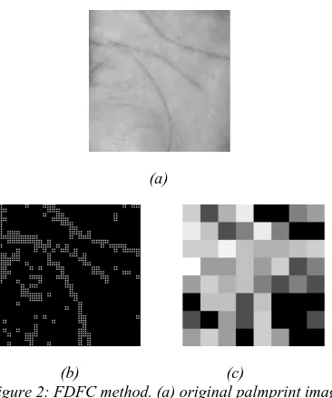
The performance of FDFC is depend on the
selection of tolerance value (є) and M. Figure 2
show the result for each step of FDFC method.
(a)
(b) (c)
Figure 2: FDFC method. (a) original palmprint image, (b) binary palmprint image, (c) palmprint feature
representation
3.2 FDIFC (Fractal Dimension Image From Fractal Codes)
The steps to extract the features of palmprint by using FDIFC method can be detailed as follows.
a. Forming binary image representation
This step is same as step (a) in FDFC method.
b. Filtering binary image
Binary image A is filtered by hmxn as follows.
( ) ( ) ( )
x y Ax y h x yA' , = , ∗ , (10)
where
∗
represent convolution process, andhmxn. represents the filter with size m x n which
all its element values are 1 (one).
c. Forming the fractal dimension image
Fractal dimension image is an image which each of its pixels represents the fractal dimension value of its neighborhood pixels. The image can be formed as follows.
( )
x y(
A( )
x y) ( )
sAD , =log ' , log (11)
( )
m
n
s
=
max
,
(12)where AD represent fractal dimension image.
d. Dividing fractal dimension image into sub blocks
The fractal dimension image A is divided into M x M blocks, each of blocks is computed its intensity mean value, and these value is used to form the feature vector:
= ,..., 2 3 , 2 ,
1 M
v µ µ µ µ (13)
where µi represent mean value of block ith.
(a) (b)
(c) (d)
Figure 3: FDIFC method. (a) original palmprint image, (b) binary palmprint image, (c) fractal dimension image,
and (d) palmprint feature representation
FDIFC method is depend on the selection
of tolerance value (є), filter size (m and n), and M
parameters. The result of each step of FDIFC method is shown in figure 3.
3.3 DIFC (Distance Image From Fractal Code)
The steps of this method can be explained as follow.
a. Forming distance and direction images
The distance image A can be formed by rules bellowed.
( )
j,k d , j 1,2,3, M1,A = i =
2
, 3 , 2 ,
1 M
k= (14)
(
) (
2)
2i i i
i
i xR xD yR yD
d = − + −
if
i
i R
y k and R x
j= = , otherwise di =0. (15)
where
(
)
i
i D
D y
x , represent top-left coordinate
of the domain block (see formula (8)) and di
represent distance between range and domain
block. The distance image is not binary image representation.
b. Filtering the distance images using hmxn
(similar with FDIFC (b))
c. Dividing filtered distance image into sub blocks
The filtered distance image is divided into M x M blocks, each of block is computed its intensity mean value, and these value is used to form the feature vector
= ,..., 2
3 , 2 ,
1 M
vJ µ µ µ µ (16)
where µi represent mean value of block ith.
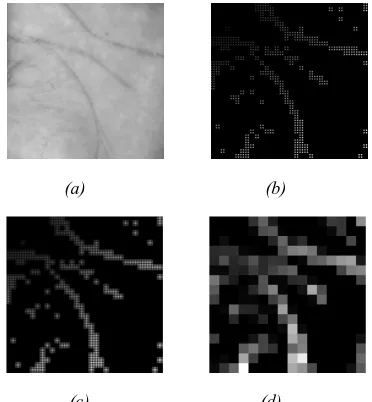
DIFC method is depend on the selection of
tolerance value (є), filter size (m and n), and M
parameters. Figure 4 show the result of DIFC method.
(a) (b)
(c) (d)
Figure 4: DIFC method. (a) original palmprint image, (b) distance image, (c) filtered image, and (d) palmprint
feature representation
3.4 AIFC (angle image from fractal code)
The method AIFC has been described in [2]. The first step of this method is the forming of angle image A as follows
( )
j,k ,j 1,2,3, M1,A =αi =
2
, 3 , 2 ,
1 M
k= (17)
i R D
R D i
x x
y y
− − =arctan
α
i iand k yR
R x j
where
(
)
i
i D
D y
x , represent top-left coordinate of
the domain block (see formula (8)) and di represent
the angle between range and domain block. The angle image is not represents binary image. The criterion bellow are added to compute the direction
.
i
α
i i D
R D
R x and y y then
x
if < ≥ α =α
i i
D R D
R x and y y then
x
if > ≥ α =180−α
i i
D R D
R x and y y then
x
if > ≤ α =180+α
i i
D R D
R x and y y then
x
if < ≤ α =360−α
90
= ≥
= D R D i
R x and y y then
x
if α
270
= ≤
= D R D i
R x and y y then
x
if α
The rest of the steps of this method are similar with the step (b) and (c) in DIFC method.
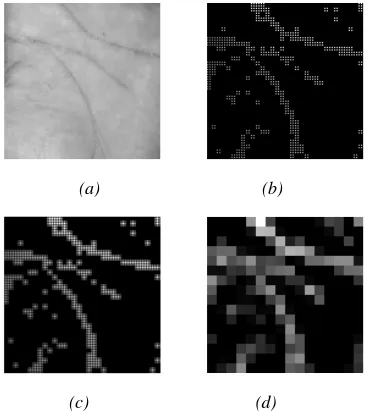
AIFC method is depend on the selection of
tolerance value (є), filter size (m and n), and M
parameters. The result of each step of FDIFC method is shown in figure 5.
(a) (b)
(c) (d)
Figure 5: AIFC method. (a) original palmprint image, (b) angle image, (c) filtered image, and (d) palmprint feature
representation
3.5 Criterion
The binary image, distance image, and angle image representation are formed based on the position of range block. The criterion bellow can be used to filter the range blocks that will be used to form those images.
1
−
=L
sizei (19)
where size represent the size of range blocks (see
formula (8)), and L represent quadtree
decomposition level. The maximum value (K) of the level L can be computed as follows.
) , min(
2 M1 M2
K = (20)
in this case K = 7 because M1 = M2 = 128.
Figure 2(b), 4(b), and 5(b) show the palmprint image representation by using the criterion with L = K and figure 3(b) is the image without the criterion.
All methods have been explained above
depend on the selection of tolerance value (є).
Figure 6 show the impact of the tolerance value to the fractal dimension image representation. According to the figure, the smaller tolerance value produced more detail information and the higher tolerance produced less detail information.
The main advantage of our proposed methods is the palmprint features can be obtained directly from the fractal codes palmprint image. Its mean we can form the palmprint feature directly from the compressed palmprint image because the compressed image is collection of fractal codes.
(a) (b)
(d) (e)
Figure 6: Fractal dimension image with various tolerance є, (a),(b),(c), and (d), represent fractal
dimension image with tolerance 2,3,4, and 5, respectively.
4. PALMPRINT FEATURE MATCHING
(
)(
)
(
)(
)
[
]
12[
(
)(
)
]
121
T s s s s T r r r r
T s s r r rs
x x x x x x x x
x x x x d
− − −
−
− − −
= (21)
where
x ,
rx
s are the mean of palmprint feature xrand xs respectively. The above equation computes
one minus normalized correlation between
palmprint feature vector xr and xs. The value of drs
is between 0 – 2. The
d
rswill be closed to 0 if xrand xs obtained from two image of the same
palmprint. Otherwise, the
d
rswill be far from 0.Figure 7 shows three groups of palmprint from the same palm and palms with similar/different line structures and their averages score are listed in Table 1. The matching score of group A are close to 0, and the matching score of group B and C are far from 0. It is easy to distinguish group A from group B and C using these scores.
Table 1:Matching Score of groups A, B, and C in figure 7
Metode Group A Group B Group C
FDFC 0,1873 0,6029 0,7121
FDIFC 0,1093 0,5462 0,5763
DIFC 0,1679 0,6563 0,8911
AIFC 0,1762 0,5057 0,6425
(a1) (a2) (a3) Group A: palms from the same person
(b1) (b2) (b3)
Group B: palms from different person with similar line structure
(c1) (c2) (c3)
Group 3: palms from different person with different line structure
Figure 7: Groups of palmprint based on typical of principal lines
5. EXPERIMENT RESULTS
Those methods have been applied for palmprint verification system. Verification system is tested using database of 1050 palmprint images, are generated from 5 samples from each of the 210 persons randomly selected. The averages of the first three images from each user were used for training and the rest were used for testing.
The performance of verification system is obtained by matching each of testing palmprint images with all of the training palmprint images in the database. A matching is noted as a correct matching if the two palmprint images are from the same palm and as incorrect if otherwise.
Figure 8 (a) show the probability distributions of genuine and imposter parts of FDFC method used tolerance = 3, and feature vector length = 256 (16 x 16 blocks). The genuine and imposter parts are estimated from correct and incorrect matching scores, respectively. Figure 8(b) show its curve characteristics. The FAR, FRR, and EER of the system are 0.3226%, 2.0734%, and 1.4523% respectively. We also tested the FDFC method with tolerance=2.5 and the result show the FAR=0.2312% and FRR=1.4423%.
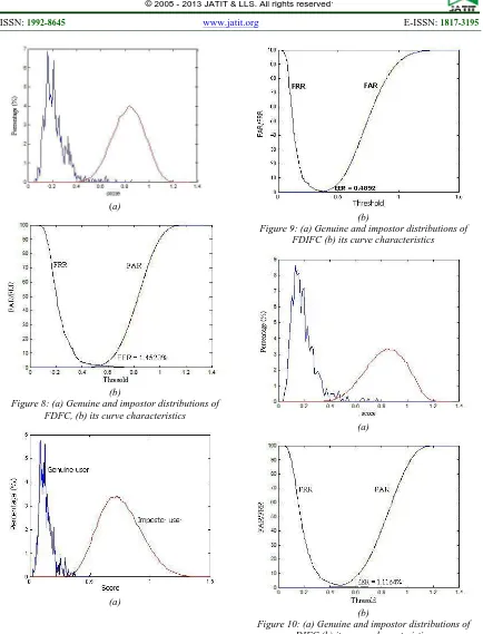
Figure 9 (a) show the probability distributions of genuine and imposter parts of FDIFC method used tolerance = 3, filter size 5 x 5, and feature vector length = 256 (16 x 16 blocks). Figure 9(b) show its curve characteristics. The FAR, FRR, and EER of the system are 0.344%, 0.479%, and 0.4092% respectively.
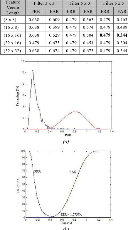
FAR and FRR values of FDIFC method in various filter size and feature vector length with tolerance = 3 are shown in table 2.
Figure 10 (a) show the probability distributions of genuine and imposter parts of DIFC method used tolerance = 3, filter size 5 x 3, and feature vector length = 256 (16 x 16 blocks). Figure 10(b) show its curve characteristics. The FAR, FRR, and EER of the system are 0.8445%, 1,7544%, and 1.1164% respectively.
(a)
(b)
Figure 8: (a) Genuine and impostor distributions of FDFC, (b) its curve characteristics
(a)
(b)
Figure 9: (a) Genuine and impostor distributions of FDIFC (b) its curve characteristics
(a)
(b)
Table 2: FAR and FRR of FDIFC method in various filter size and feature vector length with tolerance = 3 Feature
Vector Length
Filter 3 x 3 Filter 5 x 3 Filter 5 x 5
FRR FAR FRR FAR FRR FAR
(8 x 8) 0.638 0.609 0.479 0.563 0.479 0.463
(16 x 8) 0.638 0.399 0.479 0.574 0.479 0.489
(16 x 16) 0.638 0.529 0.479 0.504 0.479 0.344
(32 x 16) 0.479 0.675 0.479 0.451 0.479 0.304
(32 x 32) 0.638 0.674 0.479 0.675 0.479 0.344
(a)
(b)
Figure 11: (a) Genuine and impostor distributions of AIFC (b) its curve characteristics
FAR and FRR values of DIFC and AIFC method in various filter size and feature vector length with tolerance = 3 are shown in table 3.
Table 3: FAR and FRR of DIFC and AIFC method in various filter size and feature vector length with
tolerance = 3
Filter Size/ Number of Blocks
DIFC AIFC
FRR FAR FRR FAR
3 x 3 (8 x 8 block) 2,8708 0,7382 2,5518 0,7877
5 x 3 (8 x 8 block) 2,7113 0,8189 2,8708 0,7683
5 x 5 (8 x 8 block) 2,7113 0,7576 2,8708 0,8199
3 x 3 (16x16 block) 1,7544 0,9222 1,7544 0,8925
5 x 3 (16x16 block) 1,7544 0,8445 1,7544 0,6743
5 x 5 (16x16 block) 1,7544 0,8619 1,7544 0,6998
6. CONCLUSIONS AND FUTURE WORK
In this paper, we offer new methods (FDFC, FDIFC, DIFC and AIFC methods) based on fractal characteristics to represent the palmprint features. Those methods have been applied for palmprint verification system. The experiment results show that the proposed methods can achieve an acceptable accuracy rate. The FDIFC method shows the best performance than other proposed methods.
The main advantage of using those methods for feature extraction is the methods can be formed directly by exploitation fractal codes. Because of fractal is a great method for image coding and decoding (image compression), so in the future, we will applied those proposed methods for palmprint recognition system from compressed palmprint images.
ACKNOWLEDGEMENT
The authors would like to thank Directorate General of Higher Education of Indonesia and Udayana University for supporting this research.
REFERENCES:
[1] D. Zhang, W.K. Kong, J.You & M.Wong, Online Palmprint Identification, IEEE Transaction on Pattern Analysis and Machine Intelligence, 25(9), 2003.
[2] Darma Putra, PIFS Code based for Biometric Palmprint Verification, International Journal of Computer Science and Information Security (IJCSIS), Vol. 9, No. 2, 2011, p. 47-52. [3] T. Yokoyama, K. Sugawara & T. Watanabe,
Similarity-based image retrieval system using partitioned iterated function system codes, The 8th International Symposium on Artificial Life and Robotics, Oita, Japan, 2006.
[4] Darma Putra, Erdiawan, High Performance Palmprint Identification System Based On Two Dimensional Gabor, Telkomnika UAD, Vol. 8, No. 3, 2010, p. 195-326
[5] A.K. Jain, Ross A. & S. Pankanti, A Prototype Hand Geometry-based Verification System, IEEE Trans. On Circuits and System for Video Technology, 4(1), 1999.
[7] D. Zhang, W. Shu, Two novel characteristics in palmprint verification: datum point invariance and line feature matching, pattern recognition, 32(1), 1999, 691-702.
[8] I Ketut Gede Darma Putra, Sistem Verifikasi Biometrika Telapak Tangan dengan metode dimensi fraktal dan lacunarity, Teknologi Elektro UNUD, Vol. 8 No. 2, 2009, p. 1-6 [9] X.Q. WU, K.Q. Wang & D. Zhang, An
Approach to Line Feature Representation and Matching for Palmprint Recognition, Journal of Software, 15(6), 2004.
[10] N. Duta, A.K. Jain & K.V. Mardia, Matching of Palmprints, Pattern Recognition Letters, 23(1), 2002, 477-485.
[11] Y. Pang, T.B.J. Andrew, N.C.L. David & H.F. San, Palmprint Verification with Moments, Journal of WSCG, 12(1-3), 2003.
[12] W. LI, D. Zhang & S. XU, Palmprint Recognition Based on Fourier Transform, Journal of Software, 13(5), 2002.
[13] W. Shu & D. Zhang, Automated personal identification by palmprint, Opt. eng., 37(8), 1998, 2359-2363.
[14] A. Kumar, D.C.M.Wong, C.S. Helen, Anil K. Jain, Personal Verification using Palmprint and Hand Geometry Biometric, 2004, http:/biometrics.cse.msu.
edu/Kumar_AVBPA2003.pdf
[16] T. Connie., A. Teoh, M. Goh & D. Ngo, Palmprint Recognition with PCA and ICA, 2003,