Modular Concept and Optimization of PCMSR 250 MWe Turbine Module
Andang Widi Harto
Engineering Physics Department, Universitas Gadjah Mada Jl. Grafika no. 2, Yogyakarta 55281, Indonesia
[email protected]; [email protected]
ABSTRACT
Passive Compact Molten Salt Reactor (PCMSR) is a modular advanced nuclear reactor type. The PCMSR uses liquid fuel (molten fluoride salt) and solid graphite moderator. The PCMSR is designed as a thermal breeder reactor, thus the fuel consumption is very efficient and the amount of radioactive waste is reduced significantly. Another important features of PCMSR are inherently safe, totally passive safety system and economic. For cost reduction, PCMSR applies the concept of simplicity and modularity. PCMSR design consists of reactor module, turbine module and fuel management module. The turbine module is a regenerative multi stage Brayton cycle consists of four stages turbine and heater, four stages compressor and cooler plus one stage regenerator. The maximum temperature operation is 1323 K (1150 ºC) and minimum temperature operation is 333 K (60 ºK).
The turbine system performance analysis will be performed by calculating overall turbine system efficiency. This will be calculated using formula derived from thermodynamics multistage regenerative Brayton cycle. For the optimum design, more detail heat transfer calculation will be performed for heat transfer equipment, i.e. heaters, coolers and regenerator.
Overall efficiency calculation shows that the maximum efficiency is 56 % at optimum turbine pressure ratio of 4.3 for 4 stages turbine and 4 stages compressor. The isentropic efficiency of turbines and compressors are 93 % and 88 % respectively. The same value of heat transfer capability is designed for all heaters and compressors.
Heat transfer calculation shoes that the active length of the heaters and the coolers are approximately the same, i.e. 5 m. The active length of recuperator is 11.2 m. With these sizes of the heaters, coolers and recuperators, the estimated total length of the turbine module is roughly 20 m.
With these sizes, the turbine module can be completely fabricated in a workshop, transported and erected to power plant site.
KEYWORDS: PCMSR, modularity, turbine module optimization
1 INTRODUCTION
The worldwide human energy demand is predicted to be increase in the next decades [1]. However the conventional energy resources (coal, oil and natural gas) capability in supporting the nex energy demand will be reduced due to diminishing of these resources and the enviromental impact related to the uses conventional energy resources, i.e. greenhouse gas effect. For replacing the conventional energy uses, nuclear energy is the prominent alternative that has been proven technologically and economically.
is 5000 kilo tons [2] and the recent worldwide nuclear reactor capacity power is 400 GWe [3], the worldwide known proven nuclear fuel resources will be available only for 50 until 80 years (Energy Watch Group, 2006).
The fact that the common nuclear reactor recently use only 0.6 % - 0.7 % of the overall nuclear fuel resources means that more than 99 % of the nuclear material become waste. Estimately 12 % of the nuclear material will become spent fuel and the rest is depleted uranium. Moreover, another potential nuclear fuel resources, i.e. thorium still can not be used.
Thus, it is important to develop the next generation of nuclear reactor to use the rest of natural uranium content (U-238), reuse nuclear spent fuel or use the more abundant nuclerr fuel resource, i.e. thorium. Because all nuclear material resources can be used in such reactor, the nuclear fuel utility factor can increased with the factor of 150 times. It means that the recently known nuclear fuel resources will be available for more than 1000 years. ([Based on US Geological Survey, Mineral Commodity Sumaries (1997 – 2006) and OECD/NEA, Nuclear Energy, “Trend in Nuclear Fuel Cycle”, Paris, France (2011)).
2. FUNDAMENTAL THEORY
2.1. PCMSR (Passive Compact Molten Salt Reactor)
PCMSR (Passive Compact Molten Salt Reactor) is designed to use the natural nuclear fuel resources of thorium. The thorium in non fisile fuel thus it must be converted to the fissile fuel of U-233 by the reactor itself. PCMSR use liquid fluoride salt with the composition of 39.9 % mole 232ThF
4, mole 59.6 % 7LiF, 0.5
% of fissile component, ant small fraction of minor actinides and fission product nuclides. The exact fuel composition is depend on the initial fuel composition (i.e. depend on the fuel fabrication) and the on line fuel reprocessing during operation (Uhlir, 2009). PCMSR use graphite as moderator and structure and euthectic flinak salt (LiF-NaK-KF) as intermediate coolant (Harto, 2012).
The use of molten salt fuel combined with graphite moderator gives some important benefits, i.e. : a. Molten salt has high boiling point (1400 ºC) and graphite does not melt but will sublime at 3300 ºC
(Benes et al, 2009). It means that the reactor can be operated at very high temperature at atmospheric pressure. This gives potential to achieve high efficiency of energy conversion meanwhile eliminate the probability of the pressure expansion accident.
b. The use of liquid fuel salt allows incorporating of the on line refueling and fuel reprocessing system. The neutron poison fission product can be continually removed meanwhile the fissile and fertile fuel can be added to the reactor as it is needed (Forsbeg et al., 2004).
c. Pa-233 can be removed from reactor to allow it to decay to become U-233. In the reactor core, Pa-233 has probability to absorb neutron to become non valuable U-234. Thus removing Pa-233 can increase the reactor breeding capability (Forsbeg et al., 2004).
d. The fertile material Th-232 gives strong contribution to achieve relatively large negative temperature coefficient (Forsbeg et al., 2004).
The fuel cost of PCMSR is estimated be 1/7 of the fuel and waste cost of the recent nuclear reactor technology (LWR) (Whatley et al, 2004). This is due to the breeding capability and the application on line refueling and fuel reprocessing .
The capital cost of PCMSR is also estimated to be reduced due to the application of modularity concept. The target of the overall generating cost of PCMSR design is 2 cent US$ per kWh or even lower. The total generation cost of the recent nuclear technology is roughly 4 to 5 cent US$ per kWh.
The PCMSR design applies integral and modularity concept. PCMSR has three main modules, i.e. reactor module, turbine module and fuel management module. This paper deals with the turbine module. Each module consists of several related components and equipments those are arranged into integral design.
2.2 The Turbine Module of PCMSR
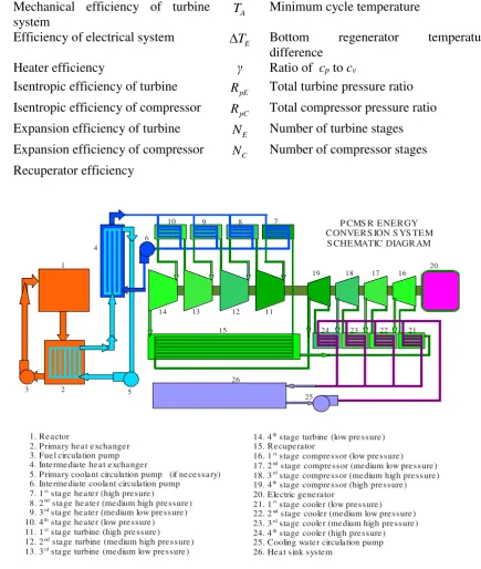
PCMSR can be operated at very high temperature due to the using of graphite moderator, fuel salt and coolant salt (Benes et al, 2004). Due to the high temperature operation, PCMSR does not use Rankine Cycle steam turbine as common for the recent nuclear power plant technology. PCMSR uses multi heating, multi cooling and regenerating Brayton Cycle gas turbine. The PCMSR uses multi heating, multi cooling and regenerating Brayton Cycle gas turbine. The PCMSR turbine system consists of multistage turbine, multistage compressor, multi stage heater, multi stage cooler and regenerator or recuperator.
Figure 1 shows the schematic diagram of a a PCMSR system using multi stage regenerative Brayton cycle (Harto, 2012).
3. METHOD
The calculation method involving three steps, i.e. - General parametric optimization
- Detail calculation on heat exchanger (heater, cooler, recuperator)
- Detail calculation on blades (turbine stator, turbine rotor, compressor rotor, compressor stator)
3.1. General parametric optimization
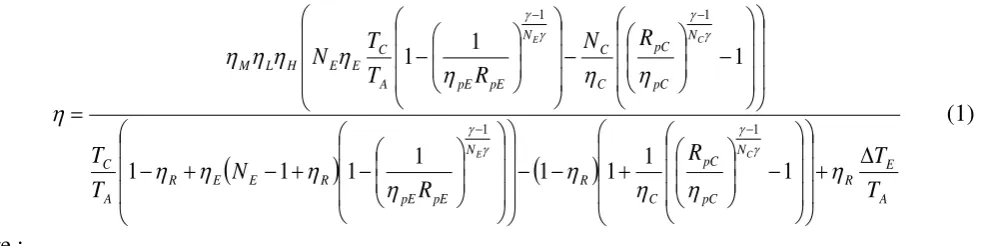
The aim of general parametric optimization is to provide the optimum operation condition that gives maximum energy conversion efficiency at turbine operation temperature suitable with reactor operation condition. Using thermodynamics cycle formulation, the energy conversion efficiency of multi heating, multi cooling and regenerating Brayton cycle can be calculated as :
Overall efficiency of turbine system
C
M
Mechanical efficiency of turbine
system A
T Minimum cycle temperature
L
Efficiency of electrical system TE Bottom regenerator temperature difference
H
Heater efficiency γ Ratio of cp to cv
E
Isentropic efficiency of turbine RpE Total turbine pressure ratio
C
Isentropic efficiency of compressor RpC Total compressor pressure ratio
pE
Expansion efficiency of turbine N E Number of turbine stages
pC
Expansion efficiency of compressor NC Number of compressor stages
R
Recuperator efficiency
1
2 3
4
5 6
7 8 9 10
11 12 13
14
15
16 17 18
19 20
21 22 23 24
25 26
P CMS R ENERGY CONVERS ION S YS TEM
S CHEMATIC DIAGRAM
1. Reactor
2. P rimary heat exchanger 3. Fuel circulation pump 4. Intermediate heat exchanger
5. P rimary coolant circulation pump (if necessary) 6. Intermediate coolant circulation pump
7. 1st stage heater (high presure)
8. 2nd stage heater (medium high pressure)
9. 3rd stage heater (medium low pressure)
10. 4th stage heater (low pressure)
11. 1st stage turbine (high pressure)
12. 2nd stage turbine (medium high pressure)
13. 3rd stage turbine (medium low pressure)
14. 4th stage turbine (low pressure)
15. Recuperator
16. 1st stage compressor (low pressure)
17. 2nd stage compressor (medium low pressure)
18. 3rd stage compressor (medium high pressure)
19. 4th stage compressor (high pressure)
20. Electric generator
21. 1st stage cooler (low pressure)
22. 2nd stage cooler (medium low pressure)
23. 3rd stage cooler (medium high pressure)
24. 4th stage cooler (high pressure)
25. Cooling water circulation pump 26. Heat sink system
Figure 1. The schematic diagram of a PCMSR system using multi stage regenerative Brayton cycle (Harto, 2012)
3.2. Detail heat exchanger calculation
and the cold fluid is cooling water. At recuperators the hot fluid is low pressure helium and the cold fluid high pressure helium. The heat exchanger calculation is conducted by using the formula of :
D Inner tube diameter U Overall heat transfer coefficient
m Fluid mass flow rate DS Overall heat exchanger inner diameter
z Axial position ULoss Heat loss coefficient
The index of 1 and 2 refer to the first fluid and the to the second fluid respectively.
3.3. Detail turbine and compressor blades calculation
Detail turbine and compressor blades calculation is performed for the optimal turbine condition only. This calculation is performed to get thermodynamics condition of the working fluid as it flows through turbine or compressor blades. The results of the calculation are pressure difference, enthalpy difference, velocity difference and temperature difference of the working fluid along the blades (i.e. from blade inlet to blade outlet). The calculation also performed to get the blade power. The blade geometry is arranged to get the overall blade power suitable with the optimum condition resulted from the previous general parametric calculation.
The method of this calculation is the solving of one dimensional mass flow, momentum and energy balances plus modified ideal gas equation of state along flow line of the gas fluid in the turbine or compressor blades. The finite difference method is used to perform these calculations.
The additional calculation (i.e. velocity triangle) is also preformed to calculate pressure drop between stator and rotor for all turbine blades or compressor blades.
4. RESULT AND DISCUSSION 4.1.General parametric optimization
Tabel 1. Efficiency of Regenerative Multistage – Equal Heating – Equal Cooling Brayton with helium working fluid and turbine inlet temperature 1373 K
2 heating stages and 2 cooling stages
2 heating stages and 2 cooling
stages 2 heating stages and 2 cooling stages
PE
R (%) RPE (%) RPE (%)
1,3745 44,1779 1,9285 52,2499 3,0252 55,4985
1,9645 51,3322 2,4041 54,0122 3,2945 55,7490
2,6568 52,3724 2,9456 54,5503 4,3223 56,1342
3,4511 51,9718 4,2667 54,4986 5,5715 56,1087
4,3474 51,0226 6,8966 53,0824 7,9251 55,6781
1 3
2 4
5
7 6
8 9
10
11
12 13
14 15
16
17
18
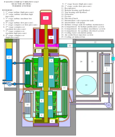
9. 1s t s ta ge he a te r (high pre s s ure )
10. 1s t
s ta ge c oole r (low pre s s ure ) 11. R e c upe ra tor
12. Bottom be a ring a nd flywhe e l 13. Top be a ring a nd flywhe e l 14. Ge ne ra tor
15. Exc ite r 16. Ele c tric a l bus h
17. Inte rme dia te s a lt e xpa ns ion ta nk 18. inte rme dia te s a lt pump
19. He lium s tora ge ta nk for turbine ma inte na nc e 20. C ompa rtme nt for he lium purific a tion s ys te m 21. C ompa rtme nt for a uxilia ry ma c hine ry s ys te m 22. C ompa rtme nt for a uxilia ry e le c tric a l s ys te m 23. C ooling wa te r c irc ula tion pump
24. Air c oole d he a t re je c tion s ys te m 25. C ooling a ir induc e d fa n P AS S IVE C OMP AC T MOLTEN S ALT
R EAC TOR (P C MS R ) TUR BINE S YS TEM
R EMAR KS : 1. 1s t
s ta ge turbine (high pre s s ure ) 2. 2nd s ta ge turbine (me dium high
pre s s ure ) 3. 3rd
s ta ge turbine (me dium low pre s s ure )
4. 4th
s ta ge turbine (low pre s s ure ) 5. 1s t s ta ge c ompre s s or (low pre s s ure )
6. 2nd
s ta ge c ompre s s or (me dium low pre s s ure ) 7. 3rd s ta ge c ompre s s or
(me dium high pre s s ure ) 8. 4th s ta ge c ompre s s or
(high pre s s ure )
20 21
19 22
23 2 4
25
.
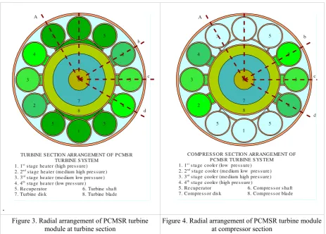
Figure 3. Radial arrangement of PCMSR turbine
module at turbine section Figure 4. Radial arrangement of PCMSR turbine module at compressor section
The 4 heating and 4 cooling stages design is then chosen as reference design and will be used for the next more detail calculation. For this reference design, the optimum turbine pressure ratio is approximately 4.3. This gives the maximum efficiency of 56 %.
4.2. Heat exchanger calculation
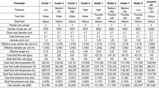
The results of heat exchanger calculation using equation (2) are shown at Table 2. The PCMSR turbine system is designed to have equal heating values for all of the heating stages and also equal cooling values for all of cooling stages. The consequence of this design is the length of heaters for all of heating stages and the length of all coolers for all of cooling stages are almost the same. Table 2 shows that the active lengths of all heaters and all coolers are approximately the same of 5 m. The recuperators has the active length of 11.2 m. Referring to the turbine system arrangement as shown at Figure 2, the length of turbine module vessel is approximately 15 m. With the addition of the length of generator and exciter (estimated as 5 m), the total length becomes 20 m.
All of the heaters, coolers and recuperators have roughly the same diameters of 1.3 m. There are totally twenty heat exchangers (8 heaters (2 parallel heaters per stage), 8 coolers (2 parallel coolers per stages), 4 parallel recuperators) that to be arranged as shown at Figure 2 or Figure 3. With this arrangement, the diameter of the turbine module vessel is approximated 7 m. This size (i.e. the total length of 20 m and the total diameter of 7 m) makes the possibility to manufacture the overall turbine module completely in a workshop. The complete turbine module is then transported to the power plant site and erected. This design full fills the modularity concept requirement.
6 1
5 5
1
5 5
4
4
3 3
2
2
7
8
TURBINE S ECTION ARRANGEMENT OF P CMS R TURBINE S YS TEM
1. 1s t s ta ge he a te r (high pre s s ure )
2. 2nd s ta ge he a te r (me dium high pre s s ure )
3. 3rd s ta ge he a te r (me dium low pre s s ure )
4. 4th s ta ge he a te r (low pre s s ure )
5. Re cupe ra tor 6. Turbine s ha ft 7. Turbine dis k 8. Turbine bla de
A
b
c
d
6 1
5 5
1
5 5
4
4
3 3
2
2
7
8
COMP RES S OR S ECTION ARRANGEMENT OF P CMS R TURBINE S YS TEM 1. 1s t s ta ge coole r (low pre s s ure )
2. 2nd
s ta ge coole r (me dium low pre s s ure ) 3. 3rd s ta ge coole r (me dium high pre s s ure )
4. 4th s ta ge coole r (high pre s s ure )
5. Re cupe ra tor 6. Compre s s or s ha ft 7. Compre s s or dis k 8. Compre s s or bla de
A
b
c
Table 2. Calculation result for heaters coolers and recuperators of PCMSR 250 MWe
Parameter Cooler 1 Cooler 2 Cooler 3 Cooler 4 Heater 1 Heater 2 Heater 3 Heater 4 recupera tor
Pressure Low Medium
low
Medium
high High High
Medium high
Medium
low Low
High / Low
Tube fluid Water Water Water Water Fluoride salt Fluoride salt Fluoride salt Fluoride salt Helium
Shell fluid Helium Helium Helium Helium Helium Helium Helium Helium Helium
Paralel unit number 2 2 2 2 2 2 2 2 4
Number of tube per unit 9750 9750 9750 9750 9000 9000 9000 9000 18250
Outer tube diameter (cm) 0.7 0.7 0.7 0.7 0.7 0.7 0.7 0.7 0.7
Tube thickness (cm) 0.1 0.1 0.1 0.1 0.1 0.1 0.1 0.1 0.1
Intertube pitch (cm) 1.2 1.2 1.2 1.2 1.25 1.25 1.25 1.25 0.91
Effective cross section per unit (m2) 1.2159 1.2159 1.2159 1.2159 1.2178 1.2178 1.2178 1.2178 1.2909 Effective diameter per unit (m) 1.2442 1.2442 1.2442 1.2442 1.2452 1.2452 1.2452 1.2452 1.3088 Effective length (m) 5.15 5.03 5.02 4.98 5.09 5.05 4.93 4.74 11.22 Tube fluid flow rate (kg/s) 220 220 220 220 427.25 427.25 427.25 427.25 150
Shell fluid flow rate (kg/s) 150 150 150 150 150 150 150 150 150
Tube fluid inlet temperature (K) 320.041 319.242 319.181 318.956 1731.000 1731.000 1731.000 1731.000 1228.064 Tube fluid outlet temperature (K) 363.000 363.000 363.000 363.000 1233.179 1233.616 1235.415 1237.690 389.014
Shell fluid inlet temperature (K) 389.014 389.637 389.597 389.839 1179.476 1179.475 1180.261 1180.262 350.661 Shell fluid outlet temperature (K) 332.939 332.961 333.013 333.001 1232.000 1232.000 1232.000 1232.000 1179.759
Tube fluid pressure drop (bar) 0.0522 0.0511 0.0510 0.0506 0.1345 0.1334 0.1302 0.1252 0.9101 Shell fluid pressure drop (bar) 0.0782 0.0533 0.0369 0.0255 0.1103 0.1488 0.1976 0.2585 0.8684 Heat transfer rate (MW) 43.3760 44.1864 44.2501 44.4792 112.1044 111.7547 110.2958 108.4797 647.5381
4.3.Turbine blades calculation
The turbine and compressor blades (both stator and rotor) are optimize for the nominal rotational speed of 3000 rpm. The thermodynamic parameter calculation result for 250 MWe PCMSR turbine system is shown at Table 3. The all heating stages and all cooling stages are designed to operate at the same heat transfer value and at the same temperature operation range.
As the consequence of this design, the all of turbine stages except the last turbine stage have almost the same power. Also the all of compressor stages except the last compressor stage have almost the same power.
The last turbine stage has lower power to get higher outlet temperature to provide adequate upper regeneration temperature difference. The last compressor stage has lower power to get lower outlet temperature to provide adequate lower regeneration temperature difference.
The geometry calculation results show that the average turbine blade radius is 157 cm (3.14 m of average diameter) and the average compressor blade diameter is 102 cm (2.04 m average radius).
5. CONCLUSION
The optimization of turbine module design of PCMSR 250 MWe has been calculated. The result of these calculation shows that it is possible to get the design that full fill modularity requirement, i,e, can be completely manufactured in a workshop and then completely transported and erected to the power plant site.
Parameter Turbine Compressor
stage 1 stage 2 stage 3 stage 4 stage 1 stage 2 stage 3 stage 4
Type Axial flow turbine Axial flow turbine
Working fluid Helium Helium
Mass flow rate (kg/s) 150 150
Pressure operation category High Medium
High
Medium
Low Low Low
Medium Low
Medium
High High
Inlet temperature (K) 1323,000 1323,000 1323,000 1323,000 333,000 333,000 333,000 333,000
Outlet temperature (K) 1179,759 1180,081 1180,786 1228,064 389,225 389,399 389,692 349,652
Inlet pressure (bar) 60,0000 44,0640 32,3648 22,5919 18,3611 26,3714 37,9729 54,5813
Outlet pressure (bar) 44,1177 32,4319 23,7978 19,3986 26,4644 38,0436 54,6364 60,9961
Pressure ratio 1,3600 1,3587 1,3600 1,2237 1,4413 1,4426 1,4388 1,1175
Isentropic efficiency (%) 93,7193 93,8501 93,2131 93,0503 88,0266 88,0756 87,9935 87,8108
Power (MW) 111,2513 111,3698 111,6715 80,1990 41,0210 41,1003 40,7634 13,4170
Total Power (MW) 414,4916 136,3017
Overall pressure ratio 3,0930 3,3220
regeneration temperature
difference (K) 48,035 (upper) 39,573 (lower)
REFERENCES
Benes, O., Cabet, C., Delpech, S., Hosnedl, P., Ignatiev, P., Konings, R., Lecarpentier, D., Matal, O., Merle-Lucotte, E., Renault, C., Uhlir, J., 2009, Aseessment of Liquid salts for Innovative Application ALISIA Deliverable (D-50), Review Report on Liquid Salts for Various Applications
Energy Watch Group, 2006, EWG Paper No 1-06, Uranium Resources and Nuclear Energy 03Dec2006 pdf Forsbeg, C. W., Peterson, P. F., Zhao, H.H., 2004, An advanced Molten salt Reactor Using High Temperature Reactor Technology, ICAPP.2004.MSR.Paper, 2004 International Congress on Advanced in Nuclear Power Plants (ICAPP ’04) Embedded International Topical Meeting, 2004 American Nuclear Sociaty Annual Meeting, Pittsburgh, Pennsylvania.
Harto. A., (2012), PCMSR General Overview Harto. A., (2012a), Sistem Turbine PCMSR
OECD/NEA, Nuclear Energy, "Trends in Nuclear Fuel Cycle", Paris, France (2001)
Uhlir, 2009, Reprocessing of Molten salt Reactor Fuel, Nuclear Research Institute Rez plc, Czech Republic US Geological Survey, Mineral Commodity Summaries (1997-2006)
Whatley. M. E., McNeese, L. E., Carter, W. L., Ferris, L. M., and Nicholson, E. L., 1969, Engineering Development of The MSBE Fuel Recycle, Chemical Engineering Division, Oak Ridge National Laboratory, Oak Ridge, Tennessee