LUCA MOGLIA
CONTROL PLANE PERFORMANCE COMPARISON IN
VIRTUALIZED BASE STATION CONTROLLER
Master of Science Thesis
Examiner: Professor Pekka Loula Examiner and topic approved by the
Council of The Faculty of Business and Built Environment 4.3.2015
ABSTRACT
MOGLIA, LUCA: Control plane performance comparison in virtualized Base Station Controller
Tampere University of Technology Master of Science Thesis, 65 pages March 2015
Master’s Degree Programme in Information Technology Major: Telecommunications Technology
Examiner: Professor Pekka Loula
Keywords: BSC, virtualization, telco cloud, SDN, NFV, SRAN
Mobile networks are in a middle of big changes. Requirements for scaling the networks while data and subscriber amounts are rapidly increasing make current network archi-tectures too ossified. Current way of deploying mobile network with proprietary hard-ware and softhard-ware of telecom equipment vendors is no longer sustainable. Telecom op-erators are having or will have profit problems with the current way. Fundamentals of building networks have to be changed.
New paradigms from IT and internet world are coming also to mobile networks. Virtu-alized IT server hardware and cloud based service model together with latest concepts like SDN (Software Defined Networking) and NFV (Network Function Virtualization) are eagerly integrated as a parts of operator’s mobile network. Although most studies are concentrating on latest generations of mobile networks, mainly 4G, also older gen-erations need to be part of the whole network portfolio. Future networks need to be transparent for users. In this scope, RAN (Radio Access Network) is in the biggest role being in the middle of the mobile user and the core network. This thesis studies the Sin-gle RAN concept from 2G BSC (Base Station Controller) point of view and what cloud, SDN and NFV would mean in that context.
There were two main objectives for this study. First, based on literature, it was studied how telecom networks are technologically emerging from the current situation towards cloud service era. That was reflected to how all virtualization and cloud related technol-ogies will possibly influence to the mobile network evolution and what high level steps are expected in the journey. As the study was focused in BSC, it was examined how the current architecture could be evolved to meet telecom industry requirements of the up-coming changes. Single (or common) radio access network is one part of the evolution and from the BSC point of view the scope was also to evaluate, what possibilities there are to merge the radio network controller functionality in 2G and 3G on top of common virtualized hardware. Secondly two different initiatives of possibly needed steps in BSC part of the evolution were studied in practice. Many small steps will be needed and the-se experiments were just very small pieces in the entity. Thothe-se, however, indicated that a lot of studies, experiments and BSC architecture redesign will be needed.
TIIVISTELMÄ
MOGLIA, LUCA: Hallintakerroksen suorituskyvyn vertailu virtualisoidussa tukiasemaohjaimessa
Tampereen teknillinen yliopisto Diplomityö, 65 sivua
Maaliskuu 2015
Pääaine: Tietoliikennetekniikka Tarkastaja: professori Pekka Loula
Avainsanat: Tukiasemaohjain, virtualisointi, teleoperaattorin pilvi, SDN, NFV, SRAN
Mobiiliverkot ovat suurten muutosten keskellä. Nykyinen verkkoarkkitehtuuri on liian kankea vastatakseen verkon skaalautumisvaatimuksiin tiedon ja tilaajamäärien nopeasti kasvaessa. Nykyinen tapa kehittää mobiiliverkkoja verkkolaitetoimittajien suljetuilla laitteisto- ja ohjelmistoratkaisuilla ei enää ole kestävää. Nykyisellä tavalla mobiiliverk-ko-operaattoreilla on tai tulee olemaan kannattavuusongelmia. Mobiiliverkkojen raken-tamisperiaatteiden täytyy muuttua.
IT- ja internetmaailman uudet ajatusmallit tekevät tuloaan myös mobiiliverkkoihin. Vir-tualisoitu IT palvelinlaitteisto, pilvipalvelumallit yhdessä viimeisimpien käsitteiden, kuten SDN (Software Defined Networking) ja NFV (Network Function Virtualization) integroidaan innolla mobiiliverkkoihin. Vaikka useimmat tutkimukset keskittyvätkin viimeisiin mobiiliverkkoteknologioihin, kuten 4G, myös vanhempien teknologioiden täytyy olla osana laajempaa mobiiliverkkoa. Tässä tarkastelussa radioverkko on suu-rimmassa roolissa mobiilikäyttäjän ja runkoverkon välissä. Tämä lopputyö tutki yhden radioverkon mallia 2G-tukiasemaohjaimen näkökulmasta, ja mitä nuo SDN ja NFV voisivat siinä yhteydessä tarkoittaa.
Tässä lopputyössä oli kaksi pääkohdetta. Ensiksi, tutkittiin kirjallisuudesta, miten mo-biiliverkot ovat teknisesti kehittymässä nykyisestä tilanteesta kohti pilvipalvelumallia. Tämä heijastuu siihen, miten kaikki virtualisointi ja pilvipalveluun liittyvät teknologiat tulevat mahdollisesti vaikuttamaan mobiiliverkkojen kehitykseen, ja mitä vaiheita kehi-tykseen liittyy. Koska lopputyö kohdistui 2G-tukiasemaohjaimeen, sen nykyistä arkki-tehtuuria arvioitiin, miten se voisi kehittyä vastatakseen mobiiliverkkojen tuleviin vaa-timuksiin. Yhteinen radioverkko on myös osa tätä kehitystä, siksi tuliaseman näkökul-masta pohdittiin myös, mitä vaihtoehtoja olisi yhdistää 2G- ja 3G-tukiasemaohjaimet toimivaksi yhteisessä virtualisoidussa laitteistossa. Toiseksi, tutkittiin käytännössä kahta mahdollista vaihetta, mitä saatetaan tarvita, kun tukiasemaohjainta virtualisoidaan. Nuo olivat pieniä vaiheita kokoisuuden kannalta mutta osoittivat, että tarvitaan paljon tutki-muksia, käytännön kokeiluja sekä tukiasemaohjaimen arkkitehtuurin uudelleen suunnit-telua lopullisten tavoitteiden saavuttamiseksi.
PREFACE
This Master of Science Thesis has been written as a part of Master of Science Degree in Information technology from the Tampere University of Technology, Tampere, Finland. The thesis work has been carried out in the Department of Telecommunications tech-nology of Pori during the year 2014 and 2015.
I would thank my mentors Juha Hartikainen (technical), Jaakko Pohjonen and Petri Tiirikka for general support in the thesis work process. I would like also thank Kimmo Koskinen, Mika Karento and Professor Pekka Loula for their contribution.
Eura, 21.3.2015 Luca Moglia
TABLE OF CONTENTS
1. INTRODUCTION ... 1
1.1 Background and motivation ... 1
1.2 Objectives ... 2
1.3 Thesis structure ... 3
2. RADIO ACCESS NETWORK ... 1
2.1 Traditional RAN architecture ... 1
2.2 Single RAN ... 3
2.2.1 Common in vendor specific solutions ... 6
3. MULTICONTROLLER BSC ... 7
3.1 General ... 7
3.2 HW architecture ... 7
3.2.1 Marker and cellular management unit (MCMU) ... 8
3.2.2 Multicontroller BSC signalling unit (BCXU) ... 9
3.2.3 Packet control unit for Multicontroller (PCUM) ... 9
3.2.4 Ethernet transmission processing for Multicontroller (ETM)... 9
3.2.5 Operation and maintenance unit (OMU) ... 10
3.3 SW architecture ... 10
3.3.1 Platform part ... 11
3.3.2 Application part... 12
4. ENABLING TECHNOLOGIES FOR A CLOUD CONTROLLER ... 15
4.1 Virtualization in general ... 15
4.1.1 Background and history ... 15
4.1.2 Technologies and techniques ... 17
4.2 Network virtualization... 21
4.2.1 Network Function Virtualization ... 21
4.2.2 Software Defined Networking ... 24
4.3 Cloud computing ... 26
4.3.1 Definition ... 27
4.3.2 Cloud computing platform ... 29
4.3.3 Telco cloud ... 31
5. TARGETS FOR BASE STATION CONTROLLER EVOLUTION ... 35
5.1 Virtualized Base Station Controller ... 35
5.2 Common virtualized controller ... 37
5.3 Cloud Controller ... 38
5.4 Multicontroller BSC architectural improvements ... 39
5.4.1 Functional unit and radio network association ... 40
5.4.2 PCUM redundancy model ... 41
5.4.3 ETME and ETMA optimization ... 41
5.4.5 MCMU scalability... 42
6. PRACTICAL EXPERIMENTS ... 43
6.1 Experiment 1, RRM in virtualized BSC... 43
6.1.1 HW and SW architecture ... 43
6.1.2 Building application SW block for testing ... 44
6.2 Experiment 2, performance comparison ... 45
6.2.1 SW and HW architecture in the experiment ... 45
6.2.2 Performed tests and comparison ... 46
7. CONCLUSIONS ... 54
7.1 Cloud controller... 54
7.2 Experiences from the practical experiments ... 54
LIST OF FIGURES
Figure 1. Key RAN elements and their control plane and user plane. ... 1
Figure 2. Evolution of radio access technologies from the RAN point of view [12]. ... 3
Figure 3. Example of benefit with SRC in multi RAT handover [10]. ... 5
Figure 4. BCN module used to build Multicontroller BSC configurations [28]. ... 7
Figure 5. Multicontroller BSC high level HW architecture and main external interfaces [28]. ... 8
Figure 6. Multicontroller BSC SW architecture. ... 11
Figure 7. Message based state transitions in TNSDL [34]. ... 14
Figure 8. Typical targets of virtualization in IT world. ... 16
Figure 9. HW and SW architecture without virtualization. ... 17
Figure 10. HW and SW architecture with bare-metal and hosted virtualization ... 18
Figure 11. Virtualized environment with KVM hypervisor and main components of KVM. ... 19
Figure 12. CPU virtualization techniques; Full Virtualization, Hardware Assisted Virtualization and Paravirtualization [35]. ... 20
Figure 13. HW and SW architecture with Container based virtualization. ... 21
Figure 14. Transformation from classical network appliance approach (of dedicated, standalone boxes) to virtualized network function approach... 22
Figure 15. High level difference between current and SDN based network architectures. ... 24
Figure 16. NIST definition for cloud computing diagram [69]. ... 27
Figure 17. OpenStack components in Telco cloud environment... 30
Figure 18. Example of different cloud deployment models for Telco environment [II]. ... 32
Figure 19. A high level path from the current architecture to a cloud controller architecture [93]. ... 35
Figure 20. Example of virtualized Multicontroller BSC environment. ... 36
Figure 21. Common 2G/3G controller in virtualized environment. ... 37
Figure 22. Common BSC and RNC with NFV, SDN and cloud perspective, control plane and user plane decoupled. ... 39
Figure 23. Suggestion for load balancer functionality in evolved Multicontroller BSC architecture. ... Error! Bookmark not defined. Figure 24. HW and SW architecture in Experiment-1. ... 44
Figure 25. HW and SW architecture in Experiment-2. ... 45
Figure 26. Figure 26. IT rack server (HP DL320e Gen8) used in Experiment 2. [95] ... 46
Figure 27. CPU load % caused by the BCXU VM from Host OS (Linux) point of view... 48
Figure 28. Generated CS control plane traffic (number of transactions in certain time) in virtualized BSC as per traffic profile described in Table 1. ... 49 Figure 29. Total CPU load % of the two CPU cores in Multicontroller BSC
BCXU. ... 50 Figure 30. Generated CS control plane traffic (number of transactions in certain
time) in Multicontroller BSC as per traffic profile described in Table 1. ... 50
TERMS AND DEFINITIONS
2G 2nd Generation in mobile network technology. Refers also to GSM, GPRS and EDGE
3G 3rd Generation in mobile network technology. Refers also to UMTS, WCDMA and HSPA
3GPP 3rd Generation Partnership Project.
4G 4th Generation in mobile network technology. Refers also to LTE.
API Application Programming Interface
ATCA Advanced Telecommunications Computing Architecture BBU Base Band Unit
BCN Box Controller Node BCXU Multicontroller BSC Signalling Unit BSC Base Station Controller BSS Business Support System
Base Station Subsystem (in GERAN) BTS Base Transceiver Station
CAPEX Capital Expenditure CBC Cell Broadcast Centre CMS Conversational Monitor System COTS Commercial Of The Shelf CSP Communication Service Provider CN Core Network
CPU Central Processing Unit CS Circuit Switched
EDGE Enhanced Data Rates for Global (GSM) Evolution EPC Evolved Packet Core
ETM Ethernet Transmission processing for Multicontroller ETSI European Telecommunications Standards Institute E-UTRAN Evolved UMTS Terrestrial Radio Access Network FU Functional Unit
GEMU GSM Emulator
GERAN GSM EDGE Radio Access Network GPRS General Packet Radio Service GSM Global System for Mobile Communication HA High Availability
HPC High Performance Computing HSPA High Speed uplink/downlink Packet Access IAAS Infrastructure As A Service
IOT Internet Of Things ISG Industry Specification Group KPI Key Performance Indicator
KVM Kernel-based Virtual Machine monitor LTE Long Term Evolution M2M Machine to Machine
MCMU Marker and Cellular Management Unit MCN Mobile Cloud Networking MGW Media Gateway MVMO Mobile Virtual Network Operator NMC Network Management Centre MME Mobility Management Entity MMI Man to Machine Interface MSC Mobile Switching Center NGMN Next Generation Mobile Networks
NE Network Element
NFV Network Function Virtualization NIC Network Interface Card
NIST National Institute of Standards and Technology OMU Operation and Maintenance Unit OPEX Operational Expenditure ONF Open Network Foundation OS Operating System OSI Open Systems Interconnection OSS Operating Support System OTT Over The Top PAAS Platform As A Service PCUM Packet Control Unit for Multicontroller PS Packed Switched
QEMU Quick Emulator
RAM Random Access Memory RAN Radio Access Network
RAT Radio Access Technology (or Type) RNC Radio Network Controller
RRM Radio Resource Management RRU Remote Radio Unit SAAS Software As A Service SDL Specification and Description Language SDN Software Defined Networking SGSN Serving GPRS Support Node S-GW Serving Gateway
SLA Service Level Agreement SMB Small and Medium Business SMLC Serving Mobile Location Centre SRAN Single Radio Access Network SRC Single Radio Controller TCO Total Cost of Ownership
TNSDL Tele Nokia Specification and Description Language TTM Time To Market
UC Use Case
UMTS Universal Mobile Telecommunication System UTRAN UMTS Terrestrial Radio Access Network VLAN Virtual LAN
VM Virtual Machine VMM Virtual Machine Monitor
Wimax Worldwide Interoperability for Microwave Access WLAN Wireless Local Area Network
1. INTRODUCTION
1.1
Background and motivation
It can be said there is a technological revolution ongoing in telecommunication industry, especially driven by evolution in mobile data technology and related services. Already for a few years telecom operators have been in high profitability pressure where current way of making business is coming to an end. Many aspects are influencing to the profit but one of the key indicators they follow is ARPU (Average Revenue Per User) [1]. It expresses the income generated by a typical subscriber per unit time in a telecommuni-cation network hence showing the direction operators network profitability is heading. The current way of building mobile network and its services is ossified. Each network node is typically dedicated and fixed vendor specific equipment with proprietary hard-ware and softhard-ware. Provisioning new network services is ineffective due to purpose-built platforms with tightly coupled software and hardware. It makes development and customization cycle long and high cost. Also different generations of mobile network technology (2G, 3G, 4G and others) are having their own equipment and software but they need to work seamlessly together. Estimating needed mobile network capacity is most difficult in radio access network side as geographically moving subscribers and time of day tend to produce uneven load to the network. As a result the nodes need to be scaled for covering nearly peak loads, practically the capacity is low and ineffectively used most of the time. [2], [3]
Covering rapidly increasing mobile network capacity requirements with the current way gets constantly more complex and costly. Amount of mobile data is increasing exponen-tially along expansion of 4G network. Different OTT (Over The Top) smartphone ap-plications (like Facebook and Whatsapp) and video in general are generating high amount off mobile network traffic and signalling. In addition, the increasing amount of IoT (Internet of Things) appliances brings lots of new subscribers to the networks, 40-50 billion by year 2020 in some estimations [4], [II].
All together these bring operator’s TCO (Total Cost of Ownership) compared to the profit to an unbearable level. Some change is needed. There is a common consensus that the telecom industry can also leverage the technology evolution used in IT world for some time already.
Virtualization and cloudification are seen as main technologies addressing the issues that the operators are having. They are going to dramatically reorganize the whole tech-nology and business of telecom industry. It will be a very interesting transformation and it is motivating to study the topic. The author of this thesis has a long experience in R&D of 2G radio network controller, BSC (Base Station Controller), hence it also made it more interesting to do a study specifically from a BSC perspective.
1.2
Objectives
The thesis can be divided in two perspectives. The first part is a literature study about how telecom networks are technologically transforming from the current situation to-wards cloud computing era. Which technologies will possibly have an influence to the evolution and which high level steps are expected during the journey? Available aca-demic and industrial studies are evaluated to form an understanding where we currently are, what has been standardized and which will be the next practical offerings in the field. Especially studies from the BSC point of view are most interesting. As the study is focused in BSC, it is examined how the current architecture could evolve to meet telecom industry requirements of upcoming changes. Single (or common) radio access network is one part of the evolution and from the BSC point of view the scope was also to evaluate, what possibilities there are to merge radio network controller functionality in 2G and 3G on top of common virtualized hardware. That kind of combined controller functionality could be further evolved as a cloud based service.
In the second part of the study two different experiments of possibly necessary evolu-tion steps in BSC part were examined in practice. Experiment 1 was an attempt to build a configuration where the selected BSC control plane application would be run on top of the same virtualized hardware and software platform that is being evaluated for the 3G radio network controller, RNC (Radio Network Controller). A further target might be a common software platform and to possibly merge BSC and RNC into a single cloud radio controller. Instead of using the current proprietary hardware, a virtualized IT server hardware would be used. After having set up a working environment, the purpose was to run basic module testing to evaluate some basic functionalities of the application. In Experiment 2 the CPU performance of the current proprietary BSC hardware was compared with virtualized IT server hardware. Quite a heavy traffic profile, from the signalling point of view, was used in this experiment.
1.3
Thesis structure
Chapter 2 introduces the current radio access network used in 2G, 3G and 4G. The main network elements and their interfaces are depicted. The chapter also gathers some as-pects of the current solutions of providing single radio access network and presents how it could evolve from the radio network controller point of view. Chapter 3 describes a current BSC network element variant from one telecom equipment vendor. Hardware and software architecture and their relation are described. Later in the thesis different virtualization and cloud architectures are sketched based on the current architecture. This network element is also used in Experiment 2 to represent the current BSC hard-ware. Chapter 4 introduces some key technologies and concepts, which are commonly seen as enablers in a telecom cloud. Chapter 5 presents some possible alternatives how the current architecture (presented in Chapter 3) could further evolve to integrate the enablers introduced in Chapter 4. Main drivers, for the enablers mentioned in chapter 4, would be to provide better radio network capacity and dynamic computing resource scaling in a cloud environment. Chapter 6 describes the two experiments, which had been selected as good practical items to be evaluated in this study. Finally Chapter 7 presents conclusions and further discussion of the covered topic.
2. RADIO ACCESS NETWORK
Radio Access Network (RAN) is a general term for the entity in telecommunication network, which is located between the mobile device and the core network. It can sup-port different Radio Access Technologies (RAT). GSM (2G, Global System for Mobile Communication) / GPRS (2.5G, General Packet Radio Service) / EDGE (2.75G, En-hanced Data Rates for Global (GSM) Evolution), UMTS (3G, Universal Mobile Tele-communication System) / HSPA (3.5G, High Speed uplink/downlink Packet Access) and/or LTE (4G, Long Term Evolution) are the most common ones. However, also Wimax (Worldwide Interoperability for Microwave Access) or WLAN (Wireless Local Area Network) can be supported but they are not in the scope in this thesis.
2.1
Traditional RAN architecture
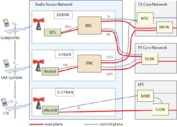
In basic concept there are separate networks for each RAT. 2G and 3G share same RAN architectural principles having dedicated controllers for a certain amount of base sta-tions. In 4G controller functionality is distributed into base stations and core network hence there is no separate controller [5]. Figure 1 illustrates the key network elements, their interfaces and how the Control and user plane flow go between them.
In 2G (GSM, GPRS and EDGE) the RAN is called GERAN (GSM EDGE Radio Ac-cess Network). It consists of BTSs (Base Transceiver Station), which are connected to BSCs with proprietary Abis interface. From BSC onwards the CS (Circuit Switched) service, voice calls or circuit switched data calls, go to CS core network via (open) A-interface. In this figure 3GPP Release-4 architecture is referred. That means MSC (Mo-bile Switching Center) is for signalling and MGW (Media Gateway) is for user data. Analogously, PS (Packed Switched) data go to PS core network via (open) Gb-interface. For both signalling and data there is common peer network element, SGSN (Serving GPRS Support Node). [6], [7]
In 3G (UMTS and HSPA) the RAN is called UTRAN (UMTS Terrestrial Radio Access Network). Its architecture is similar to GSM/GPRS/EDGE, only terms are different. Base station (called NodeB) is connected to RNC (Radio Network Controller) with Iub interface. Similarly, towards CS core network, signalling go to MSC and data to MGW. PS traffic go to PS core similarly as well, both signalling and data go to SGSN. Inter-faces are called Iu CS/PS respectively.
In 4G (LTE) the RAN is called E-UTRAN (Evolved UMTS Terrestrial Radio Access Network) which consists only of base stations called eNodeB. The Base stations are connected directly to the core network, namely to EPC (Evolved Packet Core) with S1 interfaces. In EPC there are MME (Mobility Management Entity) for signalling and S-GW (Serving Gateway) for data. In LTE all user data go over same IP network includ-ing a normal voice call for instance. [8]
The rest of the core networks and interfaces are not depicted as they are not in the scope of this thesis. Those are for example towards the Internet or Location Service center. Although not shown in the Figure 1, current base stations can be also multi RAT capa-ble, which means they support several radio technologies. There can be a single base station which can serve a 2G/3G/4G capable mobile stations. This kind of base station is connected to BSC, RNC or EPC respectively. This Single RAN (SRAN) concept is de-scribed more in chapter 2.2.
Networking planes
Three high level entities (called planes) can be identified in network functions. Control plane controls resource allocations to users, controls service switching and takes care of signalling with other network elements. User (or Data) Plane is for the data generated by network user (payload). Management plane is for functions managing the two other planes.
The network follows OSI (Open Systems Interconnection) Reference Model with all the seven layers [9], excluding user plane in the upper OSI layers. In BSC (and the scope of this thesis) point of view three first levels (physical, data link and network) are the most
essential. Also external BSC interfaces mentioned earlier (Abis, A and Gb) consist of dedicated protocols for these levels. More detailed discussion of the protocols is not in the scope of this study.
2.2
Single RAN
From the early days of mobile broadband evolution (mainly 4G but also 3G) there has been a lot of discussion of managing the evolving telecommunication networks. As GSM, HSPA and LTE are distinct technologies, developed independently and standard-ized separately, it is not easy to manage them all in the same network, which is de-ployed in a traditional way (as discussed in chapter 2.1). Figure 2 shows an example of radio access technologies used in an operator’s network. In one physical site there can be three base stations, connected to dedicated controllers for 2G and 3G, and possibly separate transport network. Operator might also have other technologies deployed, such as Wimax or WLAN [10]. Smartphone penetration with their countless applications is also one of the lead drivers push mobile broadband evolution forward [11].
Figure 2. Evolution of radio access technologies from the RAN point of view [12]. Single (or Common) RAN is not standardized technology and the telecom equipment vendors have different solutions to gather all their related solutions under an umbrella term to handle operator’s expectations. The benefits that the operators desire includes [12], [11]:
Efficient use of radio spectrum and site re-farming
Efficient shared use of hardware
Smooth evolution of GSM, HSPA and LTE
Simplified network architecture
Reduced operational expenses; one team can deploy changes to one network at the time (no need to be done separately for each RAT network element)
Converged planning, operations and management
Simplified, fully IP-based transport
Automated 3GPP compliant security
It is seen that the operators have two network strategies to consider when deploying LTE:
1. LTE overlay, where a separate LTE radio access network (RAN) is deployed alongside any the legacy 2G and 3G RAN and core networks.
2. Single RAN (SRAN), where a single base station unit provides the function-ality of a new LTE base station and also replaces legacy 2G and 3G base sta-tions at every radio site.
IT has been estimated that TCO is 21% lower with SRAN (option 2), which is a clear indication of the path that operators are choosing [13]. As mentioned earlier a RAN consists of base stations and controllers in case of 2G and 3G. To meet SRAN concept, the most of the changes are needed to base station side however. The key is to have the multi RAT base stations to effectively communicate with multi RAT mobile devices by sharing the operator’s expensive radio spectrum assets in the most appropriate way de-pending on the end-user needs. Another aspect is to manage all kind of cell types in a single heterogeneous network, like Macro-, Micro-, Pico- and Femto cells and also WiFi cells [14]. This is the area where the most of discussion of different solutions are ongoing.
From RAN architectural point of view, it is then about transferring the user data towards core network with minimum amount of investments to existing telecom network topol-ogy. As LTE base stations are connected to the core network (EPC) via all-IP network, it is an advantage if also the existing 2G and 3G base stations can also utilize the same IP based transport network.
As also controllers are part of RAN, there are also solutions available from telecom equipment vendors where 2G and 3G radio networks are controlled with a single con-troller, a combined BSC and RNC. This as well belongs to single RAN evolution alt-hough it is not a key element in overall strategy. One solution is introduced in more detail in chapter 3. Basically virtualizing RAN controllers (BSC/RNC) with shared physical resources brings dynamic and scalable resource utilization as well.
Since SRAN, especially from the controller point of view, is not yet a mature technolo-gy, there are continuous discussions ongoing in different forums between interest groups (telecom operator and telecom vendors mainly). There are different proposals to reach synergies and benefits with different technologies. One example is SRC (Single Radio Controller) concept introduced by WWRF (Wireless World Research Forum)
[10]. Idea is to gather BSC and RNC functionalities as controllers and enhance the in-terworking with LTE as well. Also core network (CN) side would be common in the proposal. As an example of benefits, handover management between cells of different technologies would be much more efficient. This is illustrated in Figure 3, where much less inter network element signalling is needed and decisions can be made already in the single radio controller level.
Figure 3. Example of benefit with SRC in multi RAT handover [10].
On top of this proposal, there could be also multi RAT evolution in base station end, as discussed earlier with traditional architecture. In this thesis the scope is in base station controller end.
This would be then a good platform for future heterogeneous networks which most probably will be a basis for next generation (5G) technology. In RAT point of view it would mean adopting existing radio technologies to as common radio network. [15] As an evolutional step of all-IP telecom network, also cloud is taking increasingly big-ger role in this area. As well as in RAN architecture the idea would be to offer radio access network as a cloud service. This is discussed more in chapter 4. However, virtu-alization of RAN meets different challenges compared with virtuvirtu-alization of mobile CN. It is seen that same IT virtualization solutions of wired network and server domain are usable also in mobile CN. RAN characteristics related to wireless access links such as user mobility, dynamic amount of user in certain area or varying radio channel condi-tions makes network virtualization of the wireless resources across multiple entities more challenging. [16]
2.2.1
Common in vendor specific solutions
There have been SRAN solutions available for several years from telecom equipment vendors. The selection is increasing all the time while also telecom operators are more and more interested in solutions for managing the evolving multi RAT telecom network. Used terms vary between vendors but there are certain similarities as well: [17], [18], [19], [20], [12], [21], [22]
In the base station end, practically all vendors have kind of modular elements for radio unit and baseband units with common hardware and which function-ality is changeable with software update. They more and less clearly had vi-sions to merge and share the functionality of these modules with different RATs.
In the controller end, nearly all vendors had solution for common BSC and RNC functionality, which also is based on modular structure. Modules have common hardware as well and the functionality of the module is changeable with software upgrade as well (based on operator needs).
In front/backhaul end, nearly all vendors had also vision (although not yet ready solutions) of shared transport network from radio interface to base sta-tion and from base stasta-tion to controller end.
These are kind in line with visions of multi RAT base stations and controllers with other parties (than telecom equipment vendors) as well, as also described earlier. Also NGMN (Next Generation Mobile Networks) Alliance1 has suggested an approach where centralized RAN can be formed with similar kind of modular components, which the vendors have already or are planning to be developed [23], [24].
1 A mobile telecommunications association of mobile operators, vendors, manufacturers and research institutes evaluating candidate technologies for the next evolutions of wireless networks
3. MULTICONTROLLER BSC
In this chapter is described a Multicontroller platform based BSC solution from one of the leading telecom equipment vendor. Target is to provide SRAN technology with high capacity and future-proof controllers for IP based radio networks. The same controller would serve GERAN and UTRAN [25].
As BSC is in the scope of this thesis, only that side is described in more detail in follow-ing chapters. Same BSC is also referred later in Chapters 5 and 6 as legacy hardware.
3.1
General
BSC can be modularly scaled to meet any traffic mix and network topology. It is pre-dicted that 2G technology need is constantly decreasing towards minimum level while 3G and further 4G are increasing [26], [12]. For this transition solutions like Multicontroller platform helps telecom operators to meet all the changing requirements for network capacity and deliver needed end-user services [25]. Multicontroller BSC supports only IP based connections on external interfaces to peer network elements. Origin of BSC SW/HW architecture is based on HW architecture, resiliency and SW model supported by DX200 platform, and usage of only TDM interfaces. PS data sup-port (GPRS, EGPRS) and IP interfaces are later add-ons to the old architecture.
3.2
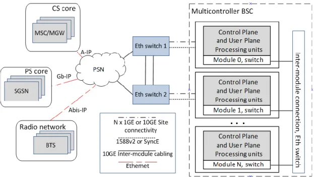
HW architecture
Multicontroller platform architecture consists of modules which can be configured for BSC or RNC with software upgrade [12]. Minimum of two BCN (Box Controller Node) module configuration forms the basic setup [27]. Modules have own power supply and they are connected to each other with Ethernet. In Figure 4there is a single module.
In the first deployment there can be all modules configured for GSM but as subscriber usage patterns change over time, the modules can be reconfigured from 2G to 3G. Module physical dimension is 4U (rack units) [28] in standard 19-inch server rack [29]. From practical part of the thesis point of view, the CPU details are the most essential. Those are described in more detail in chapter 6.2.1 where is also done comparison with the IT rack server CPU details.
In Figure 5 is presented the high level Module concept of Multicontroller BSC. Each Module can have control plane and user plane processing units as per need. Some Mod-ules can have also management plane processing units. The units are briefly introduced in next subchapters.
Figure 5. Multicontroller BSC high level HW architecture and main external interfaces
[28].
There are also depicted external interfaces to peer network elements to give better over-all view how it places to the architecture. For simplicity, over-all the interfaces are not de-picted; these are for example to NMC (Network Management Centre), SMLC (Serving Mobile Location Centre) and CBC (Cell Broadcast Centre).
3.2.1 Marker and cellular management unit (MCMU)
The MCMU has centralized management functions for controlling cells, radio channels and external interfaces for the BSC. The MCMU reserves and keeps track of the radio resources requested by the MSC and the handover procedures of the BSC. The MCMU also manages the configuration of the radio network. MCMU is 2N redundant, which means there is one unit in working at time and another is a spare unit.[28]
3.2.2 Multicontroller BSC signalling unit (BCXU)
The Multicontroller BSC signalling unit (BCXU) is a TRX-capacity unit of the BSC. It performs those BSC functions that are highly dependent on the volume of traffic. The BCXU consists of two parts, which correspond to the A-interface (towards MSC) and Packet Abis interface (towards radio network). The A-interface part of the BCXU is responsible for the following tasks:
Performing the functions of SIGTRAN based SS7 signalling
Performing all message handling and processing functions of the signalling channels connected to it
The Packet Abis interface part of the BCXU is responsible for the following tasks:
Controlling the air interface channels associated with transceivers and Abis signalling channels.
The handover and power control
BCXU is N+1 redundant, which means there is N amount of BCXU units in working state and one common spare unit to replace any of them if needed. [28]
3.2.3 Packet control unit for Multicontroller (PCUM)
The PCUM unit is an independent processing unit but logically connected to the BCXU. The PCUM unit performs all the data processing tasks related to GPRS/EDGE traffic. It implements packet switched traffic oriented Gb and Packet Abis interfaces in the BSC. The PCUM controls GPRS/EDGE radio resources and acts as the key unit in the follow-ing procedures:
GPRS/EDGE radio resource allocation and management
GPRS/EDGE radio connection establishment and management
Data transfer
Coding scheme selection
PCUM statistics
PCUM is N+M redundant, which means there is N amount of PCUM units in working state and M amount of spare units to replace any of them if needed. [28]
3.2.4 Ethernet transmission processing for Multicontroller
(ETM)
In the Multicontroller BSC, A- and Abis- interfaces are connected to an IP network. The ETM functionality terminates user plane, which is related to A (over IP) and Packet Abis (over IP) -interfaces in the BSC. The general ETM functionality contains ETME
and ETMA functionalities, where ETME handles Abis-interface and ETMA handles A-interface.
ETME is N+M redundant, which means there is N amount of ETME units in working state and M amount of spare units to replace any of them if needed. ETMA is SN+ re-dundant meaning group of units forms a working unit resource pool and traffic is redis-tributed between other units in case of failure (a pool have certain amount of extra ca-pacity for that). [28]
3.2.5 Operation and maintenance unit (OMU)
The Operation and Maintenance Unit (OMU) is an interface between the BSC and a higher-level network management system and/or the user. The OMU can also be used for local operations and maintenance. The OMU receives fault indications from the BSC. It can produce local alarm display to the user or send the fault indications to Net-work Management Centre. In the event of a fault, the OMU, together with MCMU, automatically activates appropriate recovery and diagnostics procedures within the BSC. Recovery can also be activated by the MCMU if the OMU is lost. The tasks of the OMU can be divided into four groups:
Traffic control functions
Maintenance functions
System configuration administration functions
System management functions
OMU is not redundant, which means there is only one unit [28]. In unit fault situation on above functionalities are impacted, not control- or user plane functions.
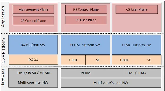
3.3
SW architecture
BSC SW architecture is divided in several program blocks which takes part of different functionalities. In high level and telecom point of view they serve control-, user- and management plane. As mentioned earlier, different planes are mainly handled by dedi-cated units but program blocks in other units has also supporting role in them.
On the other hand, software is divided in platform and application parts, as generally done. In Figure 6 is depicted the high level software architecture in Multicontroller BSC.
Figure 6. Multicontroller BSC SW architecture.
The traditional DX200 telecom functionality mainly for CS control plane and manage-ment plane runs on Intel hardware, dedicated DX OS and DX platform. On the other side PS user plane, PS control plane and CS user plane runs on Octeon hardware, Linux and Simple Executive OSs and PCUM/ETM platform software. Following subchapters describes entities in more detail.
3.3.1 Platform part
Basically platform offers different services for other platform functionalities but also overlaying application layer. Because of BSC evolution history, there are separate plat-forms used in OMU, MCMU and BCXU units than ones used by PCUM and ETM units.
OMU, MCMU and BCXU
Since early phase of GSM evolution these units were present in BSC. A dedicated pro-prietary platform software (DX200 [30]) has been in use at the beginning. In Table 1 are mentioned some of the main functionalities which are offered by platform software. Table 1. Main functionalities of platform software in OMU, MCMU and BCXU units [31].
Main category Sub category Example of functionalities
Switching Platform Basic switching services Trunk network maintenance, Common statistics, Routing analysis
Computing Platform System Maintenance - HW testing services - System supervision - Alarm system - Diagnostic
Basic computer services
- Recovery
- SW and HW administration
- TCP/IP and OSI management - LAN management
- I/O system - File system
- Licence management
- User interface management (MMI) - SIGTRAN&SS7
Operating System HW oriented functionalities such as messaging, program block management, warm up services and overload control
PCUM
Also due BSC evolution for GPRS and IP connectivity, PCUM and ETM functionality were adapted part of BSC later on. Because of this and also different nature of needed functionality a separate proprietary platform software is in use. As both units mainly serves User plane data, also platform focuses on services for processing uplink and downlink packets.
For PCUM there are separate operating systems running on different Octeon cores de-pending on the needed functionalities. Linux is serving functionalities for Gb-interface, Radio Resource management (packet switched traffic channels) and packet processing quality management. SE (Simple Executive) is serving such functionalities like for UL/DL Radio Link Layer, packet scheduler or packet framing/de-framing.
ETM
For ETM there is similarly dedicated platform layer running on Linux or SE. In User plane platform supports functionalities for processing Ethernet packet to/from radio network to ETME or to/from MGW (Media Gateway) to ETMA. There are also some supporting functionalities needed for Management and Control plane.
3.3.2 Application part
BSC application part handles the functionality specified for GSM/GPRS/EGPRS in 3GPP standards [32] with support by the platform part. Like in case of platform, also application part can divided for program blocks in OMU/MCMU/BCXU and ones in PCUM and ETM.
OMU, MCMU and BCXU
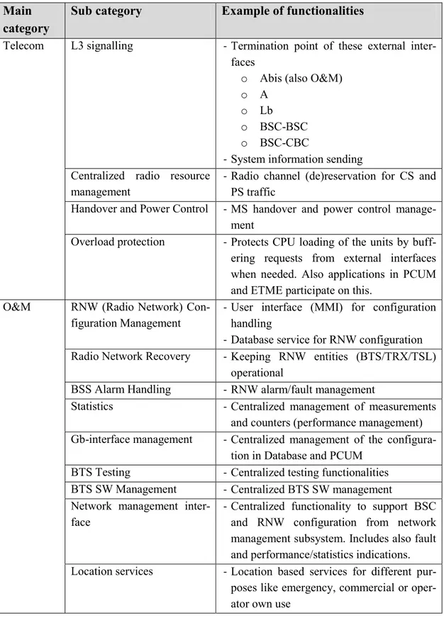
As described in Figure 6, mainly control plane (Telecom part) and management plane (O&M) functions are handled by applications running in these units. Functionalities of application part are roughly described in Table 2.
Table 2. Main functionalities of application software in OMU, MCMU and BCXU units.
Main category
Sub category Example of functionalities
Telecom L3 signalling - Termination point of these external inter-faces
o Abis (also O&M)
o A
o Lb
o BSC-BSC
o BSC-CBC
- System information sending Centralized radio resource
management
- Radio channel (de)reservation for CS and PS traffic
Handover and Power Control - MS handover and power control manage-ment
Overload protection - Protects CPU loading of the units by buff-ering requests from external interfaces when needed. Also applications in PCUM and ETME participate on this.
O&M RNW (Radio Network) Con-figuration Management
- User interface (MMI) for configuration handling
- Database service for RNW configuration Radio Network Recovery - Keeping RNW entities (BTS/TRX/TSL)
operational
BSS Alarm Handling - RNW alarm/fault management
Statistics - Centralized management of measurements and counters (performance management) Gb-interface management - Centralized management of the
configura-tion in Database and PCUM BTS Testing - Centralized testing functionalities BTS SW Management - Centralized BTS SW management Network management
inter-face
- Centralized functionality to support BSC and RNW configuration from network management subsystem. Includes also fault and performance/statistics indications. Location services - Location based services for different
pur-poses like emergency, commercial or oper-ator own use
Application level architecture is based on basic, telecom and O&M services provided by the DX200 platform and dedicated DX OS. Scope of the thesis is in application on DX200 platform hence it is described a bit further. Software is mostly implemented using proprietary programming language TNSDL (Tele Nokia Specification and De-scription Language, derived from standardized SDL-88 language) [33], which is well supported by DX OS. Software modules form modular software architecture. Each module is a kind of process running in one or more state machine (also called sub automatons), all have their own message queue. Figure 7 illustrates message queue based triggering method.
Each small circle represents a state, meaning also a message waiting point. Messages (x, y and z) are handled one by one from the queue and dedicated actions are performed, such an operation is called transition. Each higher level scenario may consist of several messages, states and transitions be-tween them. These state machine method suites well for telecommunication software with real-time requirements. [34]
Data is shared with messages between different processes and each process is using or proving services to each other. In message based communication in SDL (Specification and Description Language) sender of message not exactly knows when receiver gets the message and eventually responds to the sender hence service is called asynchronous. [33]
Figure 7. Message based state transitions in TNSDL [34].
PCUM
Application part, with assistance of the platform, controls PS resources of control plane and user plane towards proprietary Abis interface. On the other side, it communicates with SGSN via 3GPP standardised Gb-interface protocols [32]. Framing/de-framing of user plane and control plane packets for different protocol levels are the most essential part of PCUM functionality.
ETM
Application in ETME, as well with assistance of the platform, mainly handless user plane packets to/from BTS via Abis interface. For uplink direction CS data is forwarded to ETMA and PS data is forwarded to PCUM via internal IP network. For downlink direction it goes vice versa.
4. ENABLING TECHNOLOGIES FOR A CLOUD
CONTROLLER
In the past years also telecommunication companies have been increasingly interested gaining benefits of virtualization and cloudification which have been seen in the IT world. The same principles apply also in Telco network, where costly network equip-ment is running inefficiently.
This chapter introduces virtualization concept. It also discusses which other aspects need to be considered before a RAN controller can provide the services in a cloud set-ting.
4.1
Virtualization in general
Modern virtualization technologies have been commonly used in IT world for a long time. During the past few years it has been rapidly expanding also to the telecommuni-cation networks where similar benefits are expected.
Below subchapters briefly revise the background of the virtualization. After that differ-ent virtualization technologies and techniques are introduced. Some of those are also used in practical part of the thesis (Chapter 6.2).
4.1.1 Background and history
As a concept in the computing world, virtualization means hiding real hardware from the other parts of the system, including the operating system. It is a way to logically simulate or emulate physical computing resources. [35], [36], [37]
Already in the late 1950s the problem of time sharing in large foot print computing sys-tems, called main frames, was discussed. At that time hardware was expensive and needed a lot of work to setup up. Also using the computers was not so effective, engi-neers had to use key punches and submit batch jobs one at the time, meaning there was no multitasking possibilities [38]. However, in 1960s there started to be real attempts by different companies, IBM as most memorable with their S/360 followed by CP-67 [39]. In the latter the hypervisor concept was introduced for the first time with the name CMS (Conversational Monitor System), later called also VMM (Virtual Machine Monitor) [38]. Virtualization evolved further as an important technology in main frame comput-ing in late 1960s and 1970s.
During the 1980s and 1990s computing hardware costs dropped dramatically while also companies like Intel and Microsoft developed their x86 client-server architecture and multitasking operating system. It was a time of IT hardware expansion. It also meant the need for virtualization was not anymore dependent on the original time sharing prob-lem.[40]
However, different motivations appeared to further develop the virtualization in x86-environment. The trend where x86 servers were not able to simultaneously run multiple operating systems together with their low price, drove enterprises to deploy dedicated hardware for each application [38]. That caused different problems in the field [35]:
Low utilization of hardware. Each server was running inefficiently due the one application per server –logic.
Increasing physical infrastructure costs. The ever increasing amount of the dedi-cated servers needed more and more space and then increased the facility costs. In 2000s, also energy consumption for the hardware but also cooling capacity and expenses have brought own influence here.
Increasing IT management costs. The amount of cheap IT components needed a big amount of special talent work and management.
High maintenance of end-user desktops. In distributed client-server computing, managing hardware, software and their different setup combinations of enter-prises desktops became more and more complex and expensive.
Practically every component in a computer, basically in a server, can be virtualized. In addition many network devices and concepts can be also virtualized. Common with all of them is to make a single physical target appear as many, in a way multiplying it, and by that optimize the usage of physical resources [37]. Figure 8 lists some typical targets for virtualization [41], [39], [42].
Figure 8. Typical targets of virtualization in IT world.
Because there are several technical alternatives, it is not easy to compare and evaluate the pros and cons for a desired solution for the target environment. Several vendors have proprietary solution but there are also open source solutions in the market. Avail-able information is exhausting. In the next sub chapter are presented most common vir-tualization technologies and software. The scope is in virtualizing physical resources of
a computer, also a BSC processing unit, which basically also is a computer operating in telecommunication network.
4.1.2 Technologies and techniques
As discussed, the key software layer in virtualization is hypervisor (or VMM). By emu-lating physical hardware of computer (CPU, RAM, I/O or NIC) it allows multiple OSs to run on one physical computer. In this context each OS is called guest OS and with hypervisor they all appear to have the physical resources of host computer. Together with applications and guest OS they comprise a Virtual Machine (VM), a kind of virtual computer. Benefit in that is all the VMs seem have all needed resources but they still cannot disrupt each other or the host computer itself. In virtualization hardware and software are decoupled which is essential in cloud architecture as well.[35], [40]
With live migration a VM can be moved from one physical host computer to another on time even without noticeable effect to the service provided by the applications run-ning on VM [43]. This has an important mearun-ning when it comes to redundancy and maintenance but also in load balancing of physical resources of virtualized hardware. Allocating VMs to physical host computers, creating and deleting VMs can be done manually but desired way is to handle them automatically. A separate management en-tity (also a term orchestration is used) can create, move or destroy VMs based on the need of particular service. For the migration, VM is saved to file(s) in source host com-puter, transferred to new host computer and started in again there.
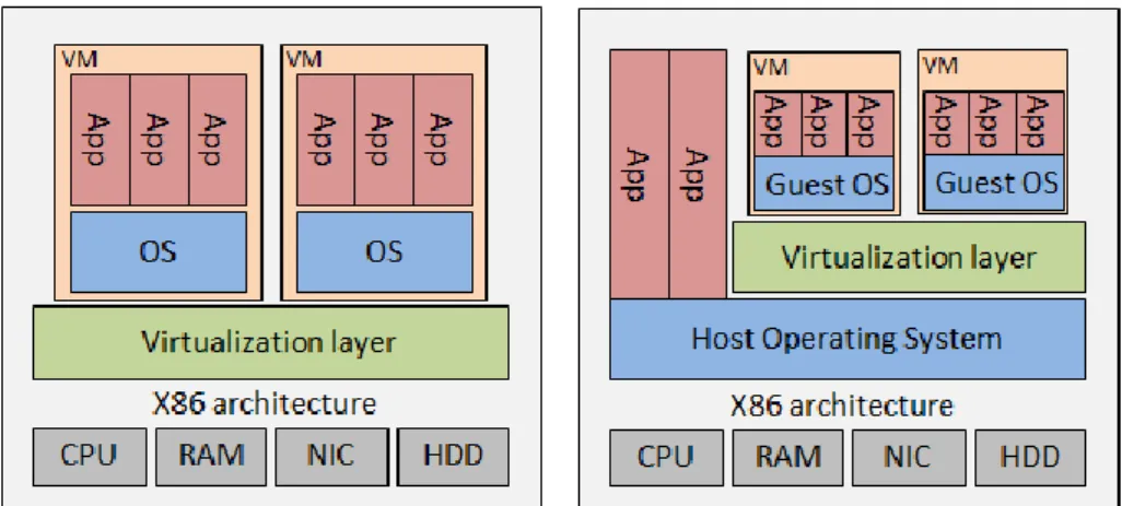
Furthermore there can be made division of two different x86 hypervisor types, namely bare metal (Type-1) and hosted (Type-2). In bare metal the virtualization layer is in-stalled directly on to a server hardware, which means there is no OS between (like Win-dows or Linux). In hosted virtualization an OS is installed first on top of physical hard-ware, like done normally without virtualisation. On top of that is installed the virtualiza-tion layer. Figure 9 illustrates the architecture before virtualization and Figure 10 with mentioned hypervisor types.
Figure 10. HW and SW architecture with bare-metal and hosted virtualization
As a further comparison there can be made some separation of these virtualization types: [36], [41], [40], [44], [45]
Some characteristics of Bare-metal virtualization (Type-1)
Since it is installed right on the physical hardware, it offers better performance and scalability than hosted virtualization. It has been observed that physical re-source utilization performance is 85% - 98% compared to native (without vir-tualization), which means there is not much overhead in most optimal cases. In ideal situation there is practically no overhead due virtualization layer, which is also one of further development targets for that. Also term native hypervisor is used for this.
Smaller range of hardware is supported.
There are more advanced features for physical resource management, high availability and security.
It supports more VMs on physical CPU.
Disadvantages are that most considerable solutions are not free. Also they are not usually running on user workstations.
Example of hypervisor softwares: Citrix XenServer, Open Source KVM, VMWare ESX Server, VMWare vSphere, Microsoft Hyper-V Server.
Some characteristics of Hosted virtualization (Type-2)
A host OS (like Windows/Linux/Mac) is required on top of the physical hard-ware.
VMs can use all the physical resources that also host OS can use.
Better hardware compatibility since the host OS offers all the hardware device drivers. This helps in deployment of systems where software is running on top of different hardware.
Physical resource utilization performance is suffering more overhead due host operating system, it has been observed that it is 70% - 90% compared to native
Example of softwares: VMWare GSX Server, Microsoft Virtual Server, Sun VirtualBox.
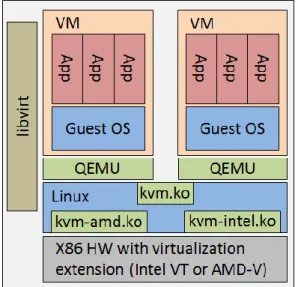
Mentioned hypervisor softwares do not always clearly belong into either category as they might have characteristics from both hypervisor types [46]. One of them is KVM (Kernel-based Virtual Machine monitor), which is very popular open source solution [47], also in telecom network virtualization deployments. Also virtualized server used in Experiment-2 (refer chapter 6.2) is configured with KVM. It is basically Type-2 hyper-visor as it runs as a process on host (Linux) OS but it also converts the kernel into a bametal hypervisor and by that way have direct access to physical hardware re-sources (Type-1) [45]. It can also benefit the advantages of hardware assisted virtualiza-tion. Figure 11 represent main components of KVM hypervisor in Linux. Each VM is handled as a normal Linux process, which are emulated with a device emulator called QEMU (Quick Emulator). KVM itself consists of a loadable kernel module/object (kvm.ko) that provides the core virtualization infrastructure, and a processor specific module, kvm-intel.ko or kvm-amd.ko directly interacting with processor via virtualiza-tion extension. Libvirt process provides management functions of KVM components. [48]
Figure 11. Virtualized environment with KVM hypervisor and main components of KVM.
CPU virtualization
CPU virtualization is probably the most common and concrete target for virtualization since the computing performance is the key metric when comparing virtualized envi-ronments with different solutions, and also to non-virtualized environment. There has been developed some techniques to further optimize virtualized x86 operating system. Main driver is in characteristics of x86-architecture, with four levels of privileges, known as Ring 0, 1, 2 and 3, which specify privileges for OS and applications to access computers hardware. The most trusted and privileged processes run in lowest protection
ring. User applications typically run in Ring 3 and OS runs in Ring 0 [49]. CPU virtual-ization techniques depicted in Figure 12 can be separated briefly as follow [49], [35], [40]:
Figure 12. CPU virtualization techniques; Full Virtualization, Hardware Assisted Vir-tualization and ParavirVir-tualization [35].
Following characteristics can be identified from the CPU virtualization techniques:
Full virtualization is providing total abstraction of underlying physical hard-ware creates complete virtualized environment where the guest OS is running. Guest OS or application on top of that does not need any modification, mean-ing they are not aware of the below virtualized environment.
OS assisted virtualization or paravirtualization presents each Virtual Ma-chine with an abstraction of the hardware which is similar but not exactly iden-tical with the underlying physical hardware. In other words, VM interface is defined so that existing non-virtualizable instructions set are replaced with eas-ily virtualized and more efficient equivalents. Guest OS needs modification so they are aware that there is virtualized environment underlying. This is draw-back since it needs porting to be compatible with different OSs.
Hardware assisted virtualization is technique developed by hardware ven-dors (like Intel VT-x and AMD-V) where there are target privileged instruc-tions with new CPU execution mode feature, which allows hypervisor to run in a new root mode in Ring-0. When selecting hardware for virtualization it is important that these kinds of techniques are supported as x86-architecture was not originally designed to handle virtualization.
Containers (LXC, Linux Containers)
Another technology compared with hypervisor is OS level, container based virtualiza-tion. In this method OS kernel is divided in multiple segments called containers or vir-tualization engines, each running a VM. In this way each VM not only shares a single
type of OS but also a single instance of an OS (or kernel of it). Figure 13 depicts this concept further.
Figure 13. HW and SW architecture with Container based virtualization.
Containers have the advantage of providing lower overhead and are often more efficient particularly in high I/O environments. However, they restrict on-top system or process to run by the same host OS (it is not possible, for instance, to run Windows inside a container on a Linux OS), and the isolation between virtual machines is in general not as good as with hypervisor. Further, if a guest manages to crash its operating system (for instance due to a bug in the Linux kernel), this can affect the entire host, because the operating system is shared between all on-top systems or processes (inside contain-ers). [46], [50]
4.2
Network virtualization
Network virtualization is seen as a key requirement for cloud networking [3]. Sharing network infrastructure with multiple tenants gains similar benefits as hardware virtual-ization in general. In a virtualvirtual-ization layer a virtual switch (vSwitch) can provide multi-player networking services for VMs.
In wider perspective there can be identified two most important network virtualization concepts, which are introduced in following subchapters. Those are NFV (Network Function Virtualization) and SDN (Software Defined Networking).
4.2.1 Network Function Virtualization
It is stated that NFV (Network Function Virtualization) is starting new era in telecom-munication networking. It provides radically new technology for deploying modern networks. [51]
Probably the first major initiative for NFV came from a group of telecom operators at
discussed earlier in the thesis. They believed that NFV could address those issues by leveraging the same IT virtualization technology to consolidate many current network elements onto industry standard high-volume servers, switches or storage, which could be located in data centres, network nodes and in the end user premises. At concept level every function taking place in their IT or telecommunication network could be virtual-ized. The concept is high level is illustrated in Figure 14. Conceptually every User plane and Control plane function in fixed and mobile network can be handled with NFV, which earlier were handled by dedicated network equipment.
Figure 14. Transformation from classical network appliance approach (of dedicated, standalone boxes) to virtualized network function approach.
At practical level single network equipment consist of several sub functionalities cov-ered by corresponding applications. Those virtualized applications are orchestrated in centralized manner, automated and remotely installed. Configurable amount of VMs are needed to cover all of the functionalities. It also further depends on an application size and complexity whether it needs one or many VMs. From BSC point of view virtualized network functionalities could be as discussed in chapter 3.3.2.
The telecom operators also foresee in the whitepaper [52] that NFV could bring many benefits such as:
Reduced cost of equipment (CAPEX) but also reduced power consumption (OPEX - running, cooling and other functions) by consolidating the hardware thus exploiting the economies of scale of the IT industry.
Increased speed of TTM (Time To Market) as also deployment (no need to in-stall and configure dedicated hardware) cycle gets simplified. Due virtualiza-tion, proprietary hardware related features are no longer needed, so only soft-ware is developed.
Common platform allows use of multi-version and multi-tenancy of network application. This allows telecom operators to share their physical resources over services and over different customer base.
Possible to introduce services by geography or customer’s general needs, ser-vice can be rapidly scaled up or down when required.
Makes evolving different eco-systems possible and encourages openness. It opens software market to pure software entrants (like small enterprises and academia). By that way it encourages for more innovation to bring new ser-vices and revenue possibilities, quickly and at lower risk.
At high level these benefits seem reasonable. However, the following challenges still needed to be addressed:
Having high performance virtualized network applications, which are portable between different virtualization environments running on different hardware. Moreover, mixing hardware, hypervisors, orchestration softwares and network applications from different vendors, without having significant integration costs and by avoiding vendor lock-in.
Having parallel use of existing dedicated hardware based network platforms but still have efficient migration path to fully virtualized network platforms.
Managing and orchestrating numerous amounts of virtualized network applica-tions (especially alongside legacy system) while handling security aspects and misconfiguration.
Scaling of services is possible only when all the virtualized functions can be automated.
Resilience to hardware and software faults needs to be handled appropriately. Basically from service point of view in similar manner as with legacy system. Shortly later a group of world’s leading telecom operators selected ETSI (European Telecommunications Standards Institute) to be home of ISG (Industry Specification Group) for NFV [53]. Since that the group has extended with many other parties, in-cluding telecommunication equipment vendors and telecom operators. Standardisation work has been going on in several smaller specification groups, and the first high level Use Cases (UC) have been identified [54], but the work still continues. Experts from the ISGs are developing the required standards for NFV as well as sharing their experiences of NFV development and early implementation.
There is also an open source project called Open Platform for NFV, which is focusing on accelerating the evolution of NFV. OPNFV project works closely with ETSI’s NFV ISG for having standards for an open NFV reference platform. [55]
4.2.2 Software Defined Networking
Computer networks have evolved in many directions during their existence of several decades. Purposes and requirements have changed a lot since early days being increas-ingly very complex and difficult to manage, which causes more risks and expenses. Network consist of many kinds equipment such routers, switches and various middle boxes like network address translators, firewalls, traffic shaping devices, server load balancers and so on. They all tend to have their own control software, especially routers and switches typically have increasing amount of complex proprietary software. Vast variety of devices, vendors, network protocols and related aspects have already a while being speeding the new evolution of the networks. [56]
Already since mid-1990 there have been various approaches to bring more intelligent to networks. Active and programmable networks and solutions such as of decoupling User plane and Control plane have been existed in different incompatible solutions many years already. Still, any revolutionary breakthrough has not occurred, until elaborated concept of SDN (Software Defined Networking) [57]. SDN is considered the first commonly agreed paradigm for coupling many challenges in the present ecosystem. It is said that SDN is transforming the whole current network architecture [58]. Also vast common interest towards SDN by academia, carriers, equipment vendors and different standardization groups [56] is telling that something revolutionary is happening.
In Figure 15 is depicted the high level difference between current and SDN based net-work architectures.
Figure 15. High level difference between current and SDN based network architectures.
In left side each box presents a network device such as switch or router, all having their own distributed control logic. In the right side the control logic is separated and central-ized to a specific SDN controller. The controller can be also physically separated and virtualized (scalability, resiliency and performance aspects). [59]
![Figure 2. Evolution of radio access technologies from the RAN point of view [12].](https://thumb-ap.123doks.com/thumbv2/123dok/2917436.2298057/17.892.174.751.525.826/figure-evolution-radio-access-technologies-ran-point-view.webp)
![Figure 3. Example of benefit with SRC in multi RAT handover [10].](https://thumb-ap.123doks.com/thumbv2/123dok/2917436.2298057/19.892.178.785.274.563/figure-example-benefit-src-multi-rat-handover.webp)
![Figure 4. BCN module used to build Multicontroller BSC configurations [28].](https://thumb-ap.123doks.com/thumbv2/123dok/2917436.2298057/21.892.171.429.951.1076/figure-bcn-module-used-build-multicontroller-bsc-configurations.webp)