DEVELOPMENT OF INTEGRATION AND ADJUSTMENT METHOD
FOR SEQUENTIAL RANGE IMAGES
K. Nagara a, T. Fuse a
a Dept. of Civil Engineering, University of Tokyo, 7-3-1 Hongo Bunkyo Tokyo 113-8656, Japan [email protected]
Commission V, WG V/4
KEY WORDS: 3D data, Range image, Point cloud, ICP algorithm, Self-calibration bundle adjustment
ABSTRACT:
With increasing widespread use of three-dimensional data, the demand for simplified data acquisition is also increasing. The range camera, which is a simplified sensor, can acquire a dense-range image in a single shot; however, its measuring coverage is narrow and its measuring accuracy is limited. The former drawback had be overcome by registering sequential range images. This method, however, assumes that the point cloud is error-free. In this paper, we develop an integration method for sequential range images with error adjustment of the point cloud. The proposed method consists of ICP (Iterative Closest Point) algorithm and self-calibration bundle adjustment. The ICP algorithm is considered an initial specification for the bundle adjustment. By applying the bundle adjustment, coordinates of the point cloud are modified and the camera poses are updated. Through experimentation on real data, the efficiency of the proposed method has been confirmed.
1. INTRODUCTION
With increasing widespread use of three-dimensional data, the demand for simplified data acquisition is also increasing. Even so far, three-dimensional data has been acquired by image processing (Photogrammetry) or laser range scanners. Image processing is an easy way for end users because users only have to take photos of the object. However, it is difficult to acquire a dense-range image in general. On the other hand, laser range scanners can acquire dense and high precision range data. However, only a few people use it because it is expensive and time-consuming. Therefore, a data acquisition method that is easy to use and can acquire dense and high precision range data is desired. Recently, the range camera, which is a simplified sensor, is widely noticed (Remondino and Stoppa, 2013). It is the camera that can obtain range images, and is much more inexpensive than laser range scanners. Its inner structure is the almost same as original cameras, and it is equipped with some infrared LEDs and the special image sensor. It measures distance by a time-of-flight method (Mutto et al., 2012). Since each element of the image sensor measures distance independently, the range camera can acquire a dense-range image in a single shot. Although it is usually used for object recognition and estimation of human pose, it can be used for three-dimensional data acquisition. However, the range camera has two drawbacks: its measuring coverage is narrow and its measuring accuracy is limited. The former drawback can be overcome by integrating sequential range images, and the latter drawback can be probably overcome by adjusting the error of point clouds. Our goal is to develop a method for integrating and adjusting sequential range images.
2. METHOD
2.1 Overview
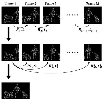
This method integrates and adjusts range images taken by a TOF (Time-of-flight) range camera. Figure 1 shows the overview of the proposed method. The number in the parenthesis is corresponding section in this paper. Firstly, point
clouds are generated from range images, and registered initially to be integrated. ICP algorithm (Besl and McKay, 1991) is employed to register. ICP algorithm assumes that the point cloud is error-free. However, the measurement accuracy of the range camera is not high. Therefore, we adjust the coordinate values of the point clouds. The coordinate values are assumed to be unknown parameters, and adjusted by bundle adjustment (Luhmann et al., 2014; Triggs et al., 2000). It re-estimates the coordinate values and camera poses. Self-calibration bundle adjustment is employed because the lens distortion of range cameras cannot be ignored (Lichti et al., 2010).
Figure 1. The overview of the proposed method
2.2 Generating point clouds
Range image is an image that each element has distance data. 3-d coor3-dinate values of each element can be calculate3-d by using this distance data (Eq. 1). Point clouds are generated as the set of these 3-d coordinate values.
Taking sequential range images
Generating point clouds (2.2)
Initial registration by ICP algorithm (2.3)
Adjusting the measurement error by self-calibration bundle adjustment (2.5) Selecting corresponding points and
2 2 2
2 2 2
2 2 2
d x X
x y f
d y Y
x y f
d f Z
x y f
(1)
where (X,Y,Z) = 3-d coordinate in the camera coordinate (x,y) = 2-d image coordinate
d = distance f = focal length
f can be acquired by camera calibration. We employed Zhang’s method (Zhang, 2000) for camera calibration by taking shots of the checkerboard and using their intensity images. However, since regular range cameras don’t have much picture elements and the measurement accuracy is not high, the focal length acquired here is used as default value, and will be re-estimated by self-calibration bundle adjustment.
2.3 Initial registration by ICP algorithm
Each point cloud is registered to a common coordinate by ICP algorithm. This algorithm is used to register two point clouds and estimate orientation and position with respect to one of the cameras. Firstly, each pair is registered and its transformation is estimated. Finally, all point clouds are registered to the first point cloud. This means they are registered to the common coordinate (Figure 2).
Figure 2. Registration to the first frame
Let ⃗⃗⃗⃗ be the point cloud of the frame k. ⃗⃗⃗⃗ is the list of (x,y,z) of the points in the k-th camera’s coordinate. If the total number of frames is M, transformations to be estimated are � , � ,…, ��− , ��− . All points clouds are registered to the first point cloud by using these transformations. For example, in the case of ⃗⃗⃗⃗ , firstly it is registered to the frame k-1 by using � − , � − . Let ⃗⃗⃗⃗ − be the registered point cloud, it is shown as Eq. 2.
1 1 1
k k k
k
k p
p R t (2)
Secondly, it is registered to the frame k-2 by using � − , � − . Let ⃗⃗⃗⃗ − be the registered point cloud, it is shown as Eq. 3.
2 1 1 2 2
)
(
k k k k k k
k
p
p
R
R
t
t
(3)
By repeating the same process, ⃗⃗⃗⃗ is registered to the point cloud of the frame 1 finally. All point clouds are registered to the common coordinate by applying these processes to the all point clouds.
In addition, each transformation from the frame 1 to the frame k (k=2,…,M) is needed to apply bundle adjustment. Let � and � be the transformation from the frame 1 to the frame k, they are shown as Eq.4.
1 1 1
1 1
1 1 1
k k k k
k k k
t t R t
R R R
(4)
Since � = � and � = �, � and � are calculated firstly. � is 3*3 identity matrix. All � and � are also calculated recursively. These transformations are used as default values in bundle adjustment.
2.4 Selecting corresponding points and integrating point clouds
All point clouds are integrated by unifying corresponding points. Corresponding points between point clouds are already known by applying ICP algorithm. These points are not exactly the same point because their correspondence is based on nearest neighbor search. However, they are assumed to be the same point if the distance between the points is sufficiently small.
We made the histogram of the distance between corresponding points (Figure 3). As a result, approximately 3,000 corresponding points are selected, and the other points are discarded.
After selecting corresponding points in each pair of frames, these points are corresponded among more than two frames. Finally, these points are unified. The coordinate values of unified points are set to the mean of values of the original points. After this section, the integrated point cloud means the set of these unified points.
2.5 Adjusting the measurement error by self-calibration bundle adjustment
The camera’s position and orientation on each frame (R,t), the coordinate values of the integrated point cloud (X,Y,Z), and the image coordinate values of the corresponding range image (x,y) are already known in the sections so far. We apply self-calibration bundle adjustment by using these data.
The default parameters of inner orientation elements are defined as follows. The focal length is estimated by the camera calibration (Section 2.2). The principal point is set to the center of the image. We employ Brown’s lens distortion model (Fryer and Brown, 1986), and all parameters (K1,K2,K3,P1,P2) are set to P1,P2 = tangential distortion coefficients
Let the total number of frames be M, and the total number of corresponding points be N. Collinearity equation of the frame � and the corresponding point � is shown as Eq. 6 (κ=1,…,M, corresponding point �
�� = projection matrix of the frame �
3. EXPERIMENTAL SETUP AND RESULTS
In this chapter, we show how we acquired data and evaluated the method.
3.1 Experimental setup
We took range images of a cube whose size was already measured (Figure 4). We acquired 9 sequential range images by moving the range camera around the cube. In addition, 8 patterns of data that were different in distance were acquired (Figure 5). We prepared a small cube additionally because some part of the big cube was out of the camera view when the camera was near to the cube. The spec of the range camera is shown in Table 1. The size of the cube is shown in Table 2.
Figure 4. Illustration of the cubes
Name DISTANZA P-401D
Resolution 128px * 126px
Angle of view 27°
Measurable distance 0.5m – 15m Measurement error 1% on the center of image
and 3m distance
Size Width: 160mm Height:
75mm Depth: 47mm
Weight 650g
Table 1. Spec of the range camera
Width Height Depth
Big cube 62.0 56.0 40.5
Small cube 26.5 13.0 20.0
Table 2. Size of the cube
3.2 Results
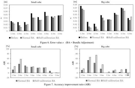
We applied our method to 8 patterns of data and evaluated it. In addition, we applied normal bundle adjustment and compared the result to the result of self-calibration bundle adjustment. We evaluated the error value e, which is the difference between the real size of the cube and the size measured on the integrated 3-d point cloud (Eq. 8), and the accuracy improvement ratio, which is defined as Eq. 9.
3
d d h h w w
e p p p (8)
where wp,hp,dp = the size measured on the point cloud w,h,d = the real size of the cube
(w: width, h: height, d:depth)
Accuracy Improvement Ratio AIR
= − × (9)
where = the error before applying an adjustment method = the error after applying an adjustment method
The results are shown on Figure 6 and Figure 7. Figure 6 shows the error value e of Before (before applying an adjustment method), Normal BA (after applying the normal bundle adjustment), and Self-calibration BA (after applying the self-calibration bundle adjustment) with each pattern. Figure 7 shows the accuracy improvement ratio of Normal BA and Self-calibration BA with each pattern. Note that the reliability of the results where the distance is 4.5m – 5.0m is not high because the density of point cloud is not high. In addition, we measured only width and depth of the big cube where the distance is 1.5m
– 2.5m because the some part of the cube is out of the camera view.
The results show that our proposed method is efficient, especially where the distance is 2.0m – 3.0m. The accuracy improvement ratio is more than 50%. Moreover, it shows that self-calibration bundle adjustment is better than normal bundle adjustment. Also, it is found that the accuracy improvement ratio becomes lower as the distance becomes further. However, the ratio is low where the distance is 1.5m. In this case, ICP algorithm might not work properly. It is suggested by Figure 8. It shows the initial re-projection error before applying bundle adjustment with each pattern. It is found that the initial re-projection error of the distance 1.5m is much higher than that of the other patterns. It is not effective to apply bundle adjustment if ICP algorithm fails and points properly match each other. The reason is described later.
Figure 7. Accuracy improvement ratio (AIR) 1.5m 2.0m 2.5m 3.0m 3.5m 4.0m 4.5m 5.0m
-20 0 20 40 60 80 100
Normal BA Self-calibration BA
1.5m 2.0m 2.5m 3.0m 3.5m 4.0m 4.5m 5.0m
-20 0 20 40 60 80 100
Normal BA Self-calibration BA
Figure 6. Error value e (BA = Bundle Adjustment)
1.5m 2.0m 2.5m 3.0m 3.5m 4.0m 4.5m 5.0m
0 0.01 0.02 0.03 0.04 0.05 0.06 0.07 0.08
Before Normal BA Self-calibration BA
0 0.01 0.02 0.03 0.04 0.05 0.06 0.07 0.08
1.5m 2.0m 2.5m 3.0m 3.5m 4.0m 4.5m 5.0m
Before Normal BA Self-calibration BA
[cm]
Small cube Big cube
e
[m] [m]
e
AIR AIR
Small cube Big cube
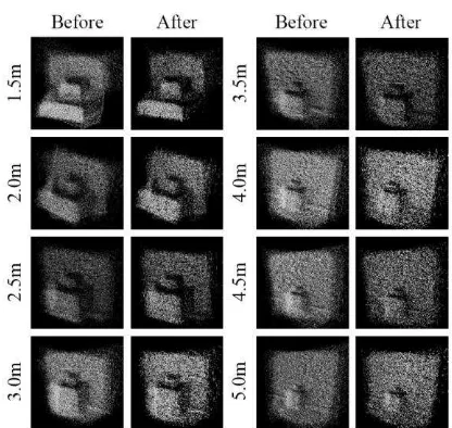
The cause of the decline of the accuracy improvement ratio may be wrong corresponding points. Generally, the measurement error of a range camera becomes larger as the distance becomes further, and point matching tends to fail in ICP algorithm if the measurement error is large. Bundle adjustment cannot correct wrong correspondence and be strongly affected by it because bundle adjustment assumes that the correspondence is true. Since correspondence is based on nearest neighbor search, not on image features, it is difficult to distinct wrong correspondence. This problem is a future issue. At last, the visualization of the integrated point clouds of the cubes are shown in Figure 9. The point clouds which are applied self-calibration bundle adjustment are shown on ‘After’ column.
Figure 8. Initial re-projection error
Figure 9. Visualization of the integrated point clouds
4. CONCLUSION
Our research developed an integration and adjustment method for sequential range images taken by a range camera. The proposed method consists of ICP algorithm and self-calibration bundle adjustment. Through experiments with the real data, the efficiency of the proposed method was confirmed. We also evaluated the influence of the distance between a camera and a target. It is found that the accuracy became lower as the distance becomes further. This is because the measurement error of the range camera becomes too large to be adjusted. In this case, outlier removal or smoothing of raw data may be effective. 3-d data acquisition by a range camera will be effective for additional measurement when data is not acquired at sufficient density or measurement is lacking. Development of a method for integrating point cloud into another point cloud with different density will enhance the value of our research.
REFERENCES
Besl, P.J. and McKay, N.D., 1991. A method for registration of 3-D shapes, IEEE transactions on Pattern Analysis and Machine Intelligence, 14(2), pp.239-256.
Fryer, J.G. and Brown, D.C., 1986. Lens distortion for close-range photogrammetry, Photogrammetric engineering and remote sensing, 52(Jan), pp.51-58.
Lichti, D. D., Kim, C. and Jamtsho, S., 2010. An integrated bundle adjustment approach to range camera geometric self-calibration, ISPRS Journal of Photogrammetry and Remote Sensing, 65(4), pp.360-368.
Luhmann, T., Robson, S., Kyle, S. and Boehm, J., 2014. Close Range Photogrammetry and 3D Imaging [2nd Edition], Walter de Gruyter GmbH, Berlin.
Mutto, C.D, Zanuttigh, P. and Cortelazzo G.M., 2012. Time-of Flight Cameras and Microsoft Kinect, Springer, New York.
Remondino, F. and Stoppa, D. eds, 2013. TOF Range-Imaging Cameras, Springer, New York.
Triggs, B., Mclauchlan, P. F., Hartley, R. I. and Fitzgibbon, A. W., 2000. Bundle Adjustment - A Modern Synthesis, In Vision Algorithms: Theory and Practice, pp.298-372.
Zhang, Z., 2000. A flexible new technique for camera calibration, IEEE Transactions on Pattern Analysis and Machine Intelligence, 22(11), pp.1330-1334.
23000 24000 25000 26000 27000 28000 29000
1.5m 2.0m 2.5m 3.0m 3.5m 4.0m 4.5m 5.0m
In
it
ia
l
re
-p
ro
je
ct
io
n
e
rr
o
r