REAL-TIME LARGE SCALE 3D RECONSTRUCTION BY FUSING KINECT AND IMU
DATA
J. Huaia, Y. Zhanga, A. Yilmaza,∗
a
Dept. of Civil, Environmental and Geodetic Engineering Dept, The Ohio State University 2036 Neil Avenue, Columbus, OH 43210 USA - (huai.3, zhang.2669, yilmaz.15)@osu.edu
Commission III, WG III/3
KEY WORDS:KinectFusion, IMU, SIFT Odometry, Large Scale Reconstruction
ABSTRACT:
Kinect-style RGB-D cameras have been used to build large scale dense 3D maps for indoor environments. These maps can serve many purposes such as robot navigation, and augmented reality. However, to generate dense 3D maps of large scale environments is still very challenging. In this paper, we present a mapping system for 3D reconstruction that fuses measurements from a Kinect and an inertial measurement unit (IMU) to estimate motion. Our major achievements include: (i) Large scale consistent 3D reconstruction is realized by volume shifting and loop closure; (ii) The coarse-to-fine iterative closest point (ICP) algorithm, the SIFT odometry, and IMU odometry are combined to robustly and precisely estimate pose. In particular, ICP runs routinely to track the Kinect motion. If ICP fails in planar areas, the SIFT odometry provides incremental motion estimate. If both ICP and the SIFT odometry fail, e.g., upon abrupt motion or inadequate features, the incremental motion is estimated by the IMU. Additionally, the IMU also observes the roll and pitch angles which can reduce long-term drift of the sensor assembly. In experiments on a consumer laptop, our system estimates motion at 8Hz on average while integrating color images to the local map and saving volumes of meshes concurrently. Moreover, it is immune to tracking failures, and has smaller drift than the state-of-the-art systems in large scale reconstruction.
1. INTRODUCTION
In recent years visual simultaneous localization and mapping (SL-AM) has focused more on real-time solutions for dense mapping with hand-held cameras, which have broad applications in navi-gation, semantic mapping and robotics. To this end, multi-view stereo (MVS) [Furukawa and Ponce, 2010] achieved relatively dense reconstruction with accurate camera tracking. However, with cameras that does not sense depth, it is challenging to re-construct surfaces without ambient light or sufficient texture. In contrast, RGB-D cameras like a Kinect, can capture color images along with the corresponding depth information at high rates. Following the advent of RGB-D sensors, a plethora of approaches have been proposed to solve for dense 3D mapping. A typical dense 3D mapping system consists of three major components: (1) Camera tracking based on the spatial alignment of consec-utive frames; (2) Live scene reconstruction based on estimated camera pose and RGB-D data; (3) Loop closure detection and pose graph optimization.
To track the RGB-D sensor reliably, previous methods [Kerl et al., 2013]- [Endres et al., 2014] only relied on RGB-D data to es-timate incremental motion. In environments with well distributed 2D and 3D features, visual odometry based solely on RGB-D data can be very accurate. However, it is prone to failures in scenes of few features and depth variations. In contrast, inertial sensors does not have such requirements on surroundings in localization. They have been used successfully in conjunction with visual sen-sors for terrestrial navigation [Kelly and Sukhatme, 2011]. An inertial measurement unit (IMU) can continuously estimate the motion with high frequency and small latency compared to vi-sual sensors, but a consumer-grade IMU is subject to large drift over time. Such a drift can be constrained by the visual odome-try estimates when the environment of rich features is traversed. Thus, it is highly desirable to fuse visual and inertial cues.
∗Corresponding author
This paper combines the ICP algorithm [Besl and McKay, 1992], SIFT-based visual odometry [Lowe, 2004], and IMU-based track-ing, to precisely and continuously estimate Kinect poses. This method does not assume good feature association and small mo-tion, thus promises to improve continuity and quality of 3D re-construction. To begin with, the relative orientation between the Kinect depth camera and the IMU was calibrated. During the al-gorithm’s execution, the ICP is utilized at all epochs; the SIFT odometry is only performed when the ICP algorithm fails; when both break down, the IMU tracking module acts as a fall-back so-lution. As for the IMU module, an extended Kalman filter (EKF) propagates the IMU states with inertial readings, and corrects them by using inclinations observed by accelerometers, and po-sition observations from ICP or SIFT odometry. Finally, detected loop closure provides further constraints to the map of which the pose graph is then optimized.
The following section discusses related work. Next, we intro-duce our 3D reconstruction system in Section 3. Then, experi-ments and results are presented in Section 4. Finally, Section 5 concludes this paper.
2. RELATED WORK
time due to high computational resource demand.
The Kinfu system [Rusu and Cousins, 2011] extends the Kinect-Fusion to large scale reconstruction by using volume shifting and volume slice extraction. However, after going through several volumes, significant tracking drift may be observed especially at the loop closures. Moreover, the ICP algorithm for tracking often breaks down with rapid motion or in planar scenes, such as corri-dor.
To reduce drift and overcome such tracking failures, Kintinu-ous [Whelan et al., 2013] combines ICP and RGB-D tracking algorithms to estimate poses. Then they adopt deformation-based loop closure for large scale dense RGB-D SLAM [Whelan et al., n.d.]. In a similar spirit, RTAB-Map [Labb´e and Michaud, 2011] used sparse features extracted from RGB images to aid ICP tracking. Moreover, it achieved large scale multi-session graph-based SLAM, which used online loop closure detection and graph-based map optimization. Shortly, [Henry et al., 2012] extracted sparse features from two consecutive color images and estimated an initial incremental motion with RANSAC-based align-ment. The initial motion is then used to initialize the ICP estima-tion. With an off-line sparse bundle adjustment, highly accurate dense maps represented by surfels were achieved.
However, the tracking modules of these systems may fail in cases of few features. To estimate motion without failures, an inertial sensor is highly advantageous in combination with a Kinect. The literature on visual-inertial fusion teems with successful appli-cations [Jones and Soatto, 2011]- [Kelly and Sukhatme, 2011]. As for fusing data collected by a Kinect and an IMU, [Nießner et al., 2014] proposed a method to robustly estimate inter-frame motion by incorporating inertial data. However, its effectiveness was only demonstrated on small areas.
Prior to combining visual and inertial cues, precise inter-sensor calibration is imperative. [Lobo and Dias, 2007]- [Mirzaei and Roumeliotis, 2008] provided basic approaches for calibrating off-the-shelf cameras and inertial sensors. The continuous approach proposed in [Furgale et al., 2013] with open source is a handy and accurate tool for IMU-camera calibration.
3. EXTENDED KINECTFUSION FOR LARGE SCALE RECONSTRUCTION
3.1 Preliminaries
Assume the RGB and depth cameras are calibrated well, then for most pixels in the RGB image, their depth can be retrieved from the depth frame captured by the depth camera. Thus, we can reconstruct a pointpfrom its coordinates in the depth frame
u= (u, v,1)T
, and the corresponding depth measurementd(u)
as follows:
whereK is the intrinsic matrix of the depth camera. Note as points are computed with regard to depth camera frames, so are the incremental motions.
In order to project a world point,pW onto the depth frame, it is first transferred from the world frame,W, to the current depth camera frame,C, through a rigid body transformation,ECW, as in equation 2.
ECW also represents the camera pose with regard to the world frame. Then the point is projected onto the depth frame through a pinhole model as in equation 3.
u=proj
Changes to the camera pose can be represented by a4×4 cam-era motion M, which is also a member ofSE(3), EC′W = M ECW =exp(µ)ECW. Hereµis the minimal representation ofM inSE(3),µ=t ωT whereωrepresents the rotation part, andtthe translation part.
3.2 Overview of Fusing the Kinect and IMU data
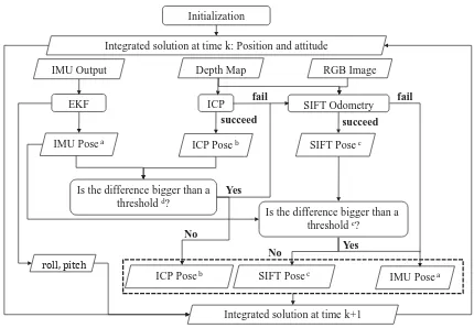
This paper presents an extended KinectFusion system that fuses measurements from a Kinect and an IMU for tracking and map-ping. The tracking component integrates three sources of odome-try information, IMU, ICP, and SIFT odomeodome-try. The IMU module integrates IMU readings to predict Kinect attitudes, and corrects IMU biases and attitudes by using accelerometer readings and position observations from ICP and SIFT odometry. The rotation between two consecutive frames is predicted by the IMU module as follows. We timestamp frames and pose estimates from the IMU with the CPU clock time. These pose estimates are stored in a buffer, from which pose estimates closest to both frames in time can be retrieved and used to compute the inter-frame rota-tion. The inter-frame translation can also be computed, however, empirically a low cost MEMS IMU only estimates relative rota-tion reliably. With such a rotarota-tion estimate, the ICP algorithm tries to align the current depth frame and the predicted surface from the reconstructed surface model. Once ICP concludes, the incremental rotation by the IMU module can be used to check the validity of its motion estimate. If ICP fails, SIFT features are extracted and matched between these two frames. Thanks to the depth frames, these features form 3D point correspondences. Then, the SIFT odometry module tries to estimate motion by minimizing discrepancies between 3D point matches, again ini-tialized and checked with the rotation estimate from the IMU. If SIFT odometry fails too, then the incremental motion is set as that of the IMU. Otherwise, the updated camera position is sent to the IMU module as observation to correct IMU states. However, empirically the IMU states do not benefit much from such obser-vations. In addition, since the Kinect often moves with small ac-celeration, the IMU can roughly sense the gravity direction, thus constraining roll and pitch drift in the long run. As a result, the roll and pitch estimated by the IMU can be used to correct Kinect poses. Figure 1 shows the work flow and heuristics of the whole extended KinectFusion system.
3.3 Large Scale KinectFusion
Initialization
Integrated solution at time k: Position and attitude
Depth Map IMU Output
Is the difference bigger than a threshold d?
Integrated solution at time k+1 RGB Image
Is the difference bigger than a thresholde?
Figure 1: Workflow of extended KinectFusion system. (a) We only use the rotation of IMU from timektok+1:{ωIM U
Ck+1Ck,0};
(b) The camera pose estimated by ICP contains the rotation and translation: {ωICP
Ck+1Ck, t
ICP
Ck+1Ck}; (c) The camera pose
esti-mated by SIFT odometry is{ωSIF T Ck+1Ck, t
SIF T
Ck+1Ck}; (d) Check if
the difference between incremental rotation estimated by ICP and that by the IMU module is greater than a threshold:||ωICP
Ck+1Ck−
ωIM U
Ck+1Ck||> Tω; (e) Check if the difference between
incremen-tal rotation estimated by the SIFT odometry and that by the IMU module is greater than a threshold: ||ωSIF T
Ck+1Ck−ω
IM U Ck+1Ck||>
Tω.
given detected revisits. With these constraints, the pose graph in terms ofSE(3)of the map is optimized with g2o [K¨ummerle et al., 2011]. Finally, using these optimized poses, volumes of point clouds or meshes are updated and combined to make the large scale map.
3.4 SIFT Odometry
Similar to the IMU module, the SIFT odometry provides incre-mental motion between two depth frames, utilizing both depth and color frames. It is invoked only when ICP fails and the color and depth frames are well synchronized. The current color frame is firstly mapped to its synchronized depth frame, so that most pixels in the color frame correspond to some points in the depth coordinate system. Secondly, SIFT interest points are extracted from the current and previous color images and matched to ob-tain correspondences. For this step, we adopted SiftGPU [Wu, 2007]. Thirdly, for each correspondence, which is associated with a 3D point, its location in each color frame is mapped to a depth pixel in the respective depth frame through the calibra-tion parameters. If both depth pixels have valid measurements, coordinates of the point observed in the previous (C) and current (C′
) depth coordinate system,pCandpC′, respectively, can be
computed by equation 1. Given a set of point matches (at least three),S=(pjC,pjC′), j= 0, ..., n−1, n >2 , the relative
camera motionEC′Ccan be obtained by iteratively updating it by a small amountµ, i.e., left-multiplication with a4×4 cam-era motion matrix,exp(µ). The camera pose update,µ, can be computed with the weighted least squares by minimizing a ro-bust objective function of discrepancies. To begin with,EC′Cis initialized as identity. Then in each iteration, the following cal-culations are performed:
1) For points in the previous frame, predict their positions in the current frame, compute the discrepancies,ej, and their weights which are determined byObj(e2
j, σ
2
T), the Tukey bi-weight ob-jective function, whereσTis a median-based estimate of the
stan-dard deviation of these discrepancies:
ej=pjC′−EC′CpjC
2) Optimizeµby using the weighted least squares method. The Jacobian for each predicted point,p= (EC′CpjC)1:3are
com-Herep×denotes the skew matrix generated from the 3-vector p. Concatenating allJj, Obj(e
2
j, σ
2
T), and ej, we can get the whole JacobianJ, weight matrixW, and error vectore, respec-tively. The optimalµis the solution for the Gauss-Newton equa-tionJTW Jµ=JTW
e.
3) UpdateEC′Cby applyingµ, i.e.,exp(µ)EC′C.
3.5 Calibration of the Kinect and IMU Rig
In order to use the incremental motion estimate from the IMU module, the transformation between Kinect cameras and the IMU needs to be known. The calibration between the RGB camera and the depth camera is done in factory and relevant parameters are written in hardware. Therefore, we only have to calibrate for the relative transformation between the depth camera and the IMU. In our tests, we used a low cost MEMS IMU, Steval-MKI062V2 developed by STMicroelectronics. It is rigidly attached to the Kinect as shown in Figure 2. Since both the Kinect depth camera and IMU can measure rotation accurately, it is easy to estimate their relative rotation,RCS.
Figure 2: Combination of Kinect and IMU sensors.
The rotation calibration was conducted in a small workspace with rich 3D features, so that ICP can reliably estimate the attitude of the depth camera. First, synchronized data from the IMU and Kinect are collected. For a specific epoch,k, it includes the an-gular rate reading from gyrosω˜S
k expressed in the IMU sensor frame, and the rotation matrix from the ICP algorithm,RW Ck.
Considering that the calibration procedure takes only a few min-utes, we assume that errors inω˜S
k consist of a constant bias and Gaussian noise. As a result, the constant bias can be estimated as the average of gyro readings in the static mode. Subtracting this bias fromω˜S
k leads to estimated angular rates in the IMU frame, b
ωS k.
Secondly, using the rotation matrices from ICP, the angular rate of the Kinect and IMU rig expressed in the depth camera frame, b
ωC
k, can be approximated by:
[t(k+ 1)−t(k)]bωC
k×=RW Ck+1
TR
whereωbC
k = RCSωbSk for allk, and the best fit ofRCS can be estimated from the SVD ofH = Pn
k=1ωb
S k(bω
C k)
T
. The least squares solution is found asRCS =U VT givenH =UΣVT [Arun et al., 1987].
The estimation of the lever arm between the Kinect cameras and the IMU is rather involved. The coarse value of lever arm be-tween the RGB camera and the IMU is manually measured. Then several calibration tests were conducted with the Kalibr pack-age [Furgale et al., 2013]. Due to the rolling shutter of the RGB camera, the lever arm estimate in different tests fluctuated about the manually measured values. As a result, the mean of these es-timates was used as the lever arm in later experiments.
3.6 IMU Odometry Based on EKF
The IMU tracking module maintains states consisting of position and velocity of the IMU in the world frame,pW
s andvWs , respec-tively, rotation from the world frame to the IMU frame expressed by a quaternion,qSW, accelerometer biasesbaand gyro biases
bg. In sum, the whole state vector is
x={pWs ,v
W
s , qSW,ba,bg} (6)
The world frame’s origin is anchored at the origin of the IMU frame at the start of an experiment. ItsZ axis is aligned with the local gravity vector. Its other two axes are defined such that the rotation between the IMU frame at the beginning of an ex-periment and the world frame involves zero yaw angle. The re-alization of this world frame is achieved by using zero velocity update (ZUPT) and accelerometer readings at a test’s start. The propagation model for the IMU states are formulated in equation 7.
dpWs dt =v
W s
dvWs
dt =RW Sa S
+gW −2ωieW×v
W s
˙
RSW = (ωieS−ω S
is)×RSW
(7)
whereωS
ie represent the Earth rotation rate with respect to the inertial frame expressed in the IMU sensor frame, andgW =
[0,0, g]T
is the nominal local gravity. Assume constant gravity in the local area, ignore the Earth rotation, and model accelerom-eter and gyro biases as random walk processes, the linearized continuous transition model is derived and given by:
dδpWs dt =δv
W s
dδvWs
dt =−RW S
˜
aS−ba
×ψS+RW S(ba+na)
˙
ψS=−ω˜S is−bg
×ψS+
bg+ng
˜
RSW = (1−ψS×)RSW b˙a=naw b˙g =ngw (8)
We use EKF to correct the states given observations such as ZUPT (equation 9) and measured gravity direction by accelerometers (equation 10). Because the small acceleration assumption does not always hold true, we apply the gravity observation model to constrain roll and pitch only when the magnitude of the estimated acceleration,k˜aS−bak, deviates fromgless than a cutoff value (our tests used 1.5m/s2
):
0=vWs +nv (9)
gW =−RW S(˜aS−ba) +ng (10)
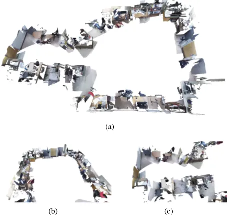
(a)
(b) (c)
Figure 3: Meshes for the office after loop closure. The upper pic-ture shows the whole loop of the office and the lower two views represent the details of the two small loops. Since we didn’t cap-ture sufficient data in the second small loop, there are some miss-ing parts here.
4. EXPERIMENTS AND RESULTS
Several indoor experiments are conducted to validate our method’s advantages over other motion estimation methods, including ar-eas with insufficient depth and color features. The proposed method runs in real time on a computer with a 2.4 GHz CPU and 8 GB RAM. Three experiments are presented: One was conducted in an large office of travel distance around 36m, one in a corridor of around 65m, and the last on several flights of stairs of around 83 m. Each test was started with a static session of about 45 secondsto calibrate the IMU and to ensure the initial roll and pitch converged. In order to observe the drift effect, each test contained a loop. For comparison, state-of-the-art tracking meth-ods, ICP and SIFT, were used to estimate motion for the datasets collected in three experiments. The ICP based approach broke down in areas without enough depth features, such as corridor and stairs. SIFT odometry was more robust to failures than ICP but often got rather coarse orientations in featureless areas. In contrast, our combined odometry (ICP+SIFT+IMU) ran through entire experiments smoothly and resulted in less drift for large scale reconstruction. We present the trajectories generated by the SIFT odometry, our combined odometry (ICP+SIFT+IMU) and the combined odometry with loop closure. The trajectory from ICP is not presented because it frequently failed due to insuffi-cient depth features.
For the test in an office, the meshes of the office area after loop closure are shown in figure 3. The two closer views at its second row illustrates details of meshes. The missing and discontinuous texture are primarily due to the volume shifting step as each vol-ume is confined by a cube and cannot integrate texture beyond it. In the future, we will use a volume slicing and rotating technique as in Kintinuous [Whelan et al., 2013] to solve this problem. Fig-ure 4 shows the view of trajectories in X-Z plane of the depth camera frame at the test start.
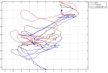
x [m]
-12 -10 -8 -6 -4 -2 0 2
-4 -3 -2 -1 0 1 2 3 4 5
6 SIFT
Combined Combined with LC
Figure 4: Trajectories projected to X-Z plane of the depth camera frame at the start of the office test. ”◦” marks the starting point and ”∗” the finish point. Large orientation erros are observed in the SIFT odometry. Combined odometry gives better results, but still suffers in heading. This may be caused by many movements close to pure rotations in the test. The loop closure handles the orientation inconsistency very well.
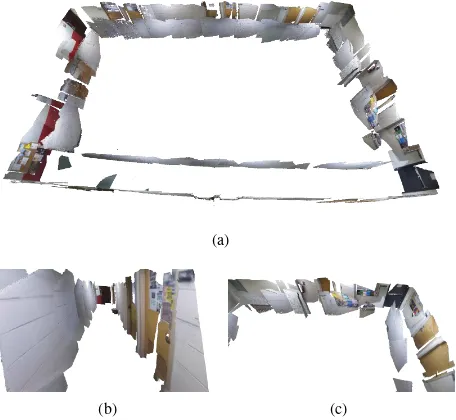
(a)
(b) (c)
Figure 5: Meshes for the corridor after loop closure. The upper picture shows the whole loop of the corridor and the lower two views represent the inner view and one part of the loop. The missing and discontinuous texture are due to the volume shifting step as each volume is confined by a cube and cannot integrate texture beyond it.
plane are drawn in figure 6. For the test in a stairway, the meshes of four flights after loop closures are depicted in figure 7. Figure 8 shows the corresponding trajectories.
5. CONCLUSION
We presented an extended KinectFusion system for real-time large scale 3D reconstruction by fusing Kinect and IMU data. In order to estimate sensor pose robustly, the ICP algorithm, SIFT odom-etry, and the IMU odometry are combined into a single pipeline. This combined odometry bridges tracking failures often experi-enced by methods only using RGB and depth information upon
x [m]
-16 -14 -12 -10 -8 -6 -4 -2 0
-8 -6 -4 -2 0 2
SIFT Combined Combined with LC
Figure 6: Trajectories projected to X-Z plane of the depth camera frame at the start of the corridor test. ”◦” marks the starting point and ”∗” the finish point. The SIFT odometry keeps the shape well despite a scale change. Combined odometry gives better results in orientation and scale. The loop closure removes the trajectory inconsistency.
(a)
(b) (c)
Figure 7: Meshes for stairs after loop closure. The upper picture shows the panorama of four flights of stairs and the lower two views represent the stairs to the second and fourth floor. The missing and discontinuous texture is partially caused by quick motion and hence inadequate color images.
abrupt camera motion or inadequate features. It is verified that the system we developed outperforms state-of-the-art methods in reducing drift and ensuring continuous motion estimates. Based on motion estimation from the combined odometry and loop clo-sure, large scale reconstruction of good quality is achieved.
REFERENCES
Arun, K. S., Huang, T. S. and Blostein, S. D., 1987. Least-squares fitting of two 3-d point sets. Pattern Analysis and Machine Intel-ligence, IEEE Transactions on (5), pp. 698–700.
Besl, P. J. and McKay, N. D., 1992. A method for registration of 3-d shapes. IEEE transactions on pattern analysis and machine intelligence 14(2), pp. 239–256.
x [m]
-7 -6 -5 -4 -3 -2 -1 0 1 2 3
-7 -6 -5 -4 -3 -2 -1 0
1 SIFT
Combined Combined with LC
Figure 8: Trajectories projected to X-Y plane of the depth camera frame at the start of the stairway test. ”◦” marks the starting point and ”∗” the finish point. Combined odometry gives better results in orientation and scale. The loop closure removes the trajectory inconsistency.
2014. 3-d mapping with an rgb-d camera. Robotics, IEEE Trans-actions on 30(1), pp. 177–187.
Furgale, P., Rehder, J. and Siegwart, R., 2013. Unified temporal and spatial calibration for multi-sensor systems. In: Intelligent Robots and Systems (IROS), 2013 IEEE/RSJ International Con-ference on, IEEE, Tokyo, Japan, pp. 1280–1286.
Furukawa, Y. and Ponce, J., 2010. Accurate, dense, and robust multiview stereopsis. Pattern Analysis and Machine Intelligence, IEEE Transactions on 32(8), pp. 1362–1376.
Henry, P., Krainin, M., Herbst, E., Ren, X. and Fox, D., 2012. Rgb-d mapping: Using kinect-style depth cameras for dense 3d modeling of indoor environments. The International Journal of Robotics Research 31(5), pp. 647–663.
Izadi, S., Kim, D., Hilliges, O., Molyneaux, D., Newcombe, R., Kohli, P., Shotton, J., Hodges, S., Freeman, D., Davison, A. et al., 2011. Kinectfusion: real-time 3d reconstruction and interaction using a moving depth camera. In: Proceedings of the 24th an-nual ACM symposium on User interface software and technol-ogy, UIST ’11, ACM, New York, NY, USA, pp. 559–568.
Jones, E. S. and Soatto, S., 2011. Visual-inertial navigation, map-ping and localization: A scalable real-time causal approach. The International Journal of Robotics Research 30(4), pp. 407–430.
Kelly, J. and Sukhatme, G. S., 2011. Visual-inertial sensor fusion: Localization, mapping and sensor-to-sensor self-calibration. The International Journal of Robotics Research 30(1), pp. 56–79.
Kerl, C., Sturm, J. and Cremers, D., 2013. Dense visual slam for rgb-d cameras. In: Intelligent Robots and Systems (IROS), 2013 IEEE/RSJ International Conference on, IEEE, Tokyo, Japan, pp. 2100–2106.
K¨ummerle, R., Grisetti, G., Strasdat, H., Konolige, K. and Bur-gard, W., 2011. g 2 o: A general framework for graph optimiza-tion. In: Robotics and Automation (ICRA), 2011 IEEE Interna-tional Conference on, IEEE, Shanghai, China, pp. 3607–3613.
Labb´e, M. and Michaud, F., 2011. Memory management for real-time appearance-based loop closure detection. In: Intelli-gent Robots and Systems (IROS), 2011 IEEE/RSJ International Conference on, IEEE, San Francisco, CA, USA, pp. 1271–1276.
Lobo, J. and Dias, J., 2007. Relative pose calibration between visual and inertial sensors. The International Journal of Robotics Research 26(6), pp. 561–575.
Lowe, D. G., 2004. Distinctive image features from scale-invariant keypoints. International Journal of Computer Vision 60(2), pp. 91–110.
Mirzaei, F. M. and Roumeliotis, S., 2008. A kalman filter-based algorithm for imu-camera calibration: Observability analysis and performance evaluation. Robotics, IEEE Transactions on 24(5), pp. 1143–1156.
Newcombe, R. A., Izadi, S., Hilliges, O., Molyneaux, D., Kim, D., Davison, A. J., Kohi, P., Shotton, J., Hodges, S. and Fitzgib-bon, A., 2011. Kinectfusion: Real-time dense surface mapping and tracking. In: Mixed and augmented reality (ISMAR), 2011 10th IEEE international symposium on, IEEE, Basel, Switzer-land, pp. 127–136.
Nießner, M., Dai, A. and Fisher, M., 2014. Combining inertial navigation and icp for real-time 3d surface reconstruction. Euro-graphics 2014-Short Papers pp. 13–16.
Rusu, R. B. and Cousins, S., 2011. 3d is here: Point cloud li-brary (pcl). In: Robotics and Automation (ICRA), 2011 IEEE International Conference on, IEEE, Shanghai, China, pp. 1–4.
Whelan, T., Johannsson, H., Kaess, M., Leonard, J. J. and Mc-Donald, J., 2013. Robust real-time visual odometry for dense rgb-d mapping. In: Robotics and Automation (ICRA), 2013 IEEE International Conference on, IEEE, Karlsruhe, Germany, pp. 5724–5731.
Whelan, T., Kaess, M., Leonard, J. J. and McDonald, J., n.d. Deformation-based loop closure for large scale dense rgb-d slam. In: Intelligent Robots and Systems (IROS), 2013 IEEE/RSJ In-ternational Conference on, Tokyo, Japan, pp. 548–555.