5.1 Introduction
Most structures are assemblies of large numbers of elements and the performance of the complete structure depends principally on the types of element which it contains and on the ways in which these are connected
together. The classification of elements was considered in Chapter 4, where the principal influence on element type was shown to be the shape of the element in relation to the pattern of the applied load. In the context of
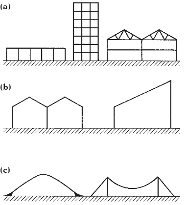
architecture, where gravitational loads are normally paramount, there are three basic arrangements: post-and-beam, form-active and semi-form-active (Fig. 5.1). Post-and-beam structures are assemblies of vertical and
horizontal elements (the latter being non-form-active); fully form-active structures are
complete structures whose geometries conform to the form-active shape for the principal load which is applied; arrangements which do not fall into either of these categories are semi-form-active.
The nature of the joints between elements (be they form-active, semi-form-active or non-form-active) significantly affects the
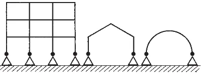
performance of structures and by this criterion they are said to be either ‘discontinuous’ or ‘continuous’ depending on how the elements are connected. Discontinuous structures contain only sufficient constraints to render them stable; they are assemblies of elements connected together by hinge-type joints1and most of them are also statically determinate (see Appendix 3). Typical examples are shown diagrammatically in Fig. 5.2. Continuous structures, the majority of which are also statically indeterminate (see Appendix 3), contain more than the minimum number of constraints required for stability. They usually have very few hinge-type joints and many have none at all (Fig. 5.3). Most structural
geometries can be made either continuous or discontinuous depending on the nature of the connections between the elements.
The principal merit of the discontinuous structure is that it is simple, both to design and to construct. Other advantages are that its behaviour in response to differential
settlement of the foundations and to changes in the lengths of elements, such as occur
47
Complete structural
arrangements
1 A hinge joint is not literally a hinge; it is simply a joint which is incapable of preventing elements from rotating relative to each other; most junctions between elements fall into this category.
Fig. 5.1 The three categories of basic geometry. (a) Post-and-beam. (b) Semi-form-active. (c) Form-active.
(a)
(b)
when they expand or contract due to
variations in temperature, does not give rise to additional stress. The discontinuous structure adjusts its geometry in these
circumstances to accommodate the movement without any internal force being introduced into the elements. A disadvantage of the discontinuous structure is that, for a given application of load, it contains larger internal forces than a continuous structure with the same basic geometry; larger elements are required to achieve the same load carrying capacity and it is therefore less efficient. A further disadvantage is that it must normally be given a more regular geometry than an equivalent continuous structure in order that it can be geometrically stable. This restricts the freedom of the designer in the selection of the form which is adopted and obviously affects the shape of the building which can be supported. The regular geometry of typical steel frameworks, many of which are discontinuous (see Figs 2.11 and 5.16) illustrate this. The discontinuous structure is therefore a rather basic structural arrangement which is not very efficient but which is simple and therefore economical to design and construct.
The behaviour of continuous structures is altogether more complex than that of discontinuous forms. They are more difficult both to design and to construct (see Appendix 3) and they are also unable to accommodate movements such as thermal expansion and foundation settlement without the creation of internal forces which are additional to those caused by the loads. They are nevertheless potentially more efficient than discontinuous structures and have a greater degree of
geometric stability. These properties allow the designer greater freedom to manipulate the overall form of the structure and therefore of the building which it supports. Figures 1.9 and 7.37 show buildings with continuous structures which illustrate this point.
5.2 Post-and-beam structures
Post-and-beam structures are either
loadbearing wall structures or frame structures. Both are commonly used structural forms and within each type a fairly wide variety of
different structural arrangements, of both the continuous and the discontinuous types, are possible. A large range of spans is also possible depending on the types of element which are used.
The loadbearing wall structure is a post-and-beam arrangement in which a series of horizontal elements is supported on vertical walls (Fig. 5.4). If, as is usually the case, the joints between the elements are of the hinge type, the horizontal elements are subjected to pure bending-type internal forces and the vertical elements to pure axial compressive internal forces when gravitational loads are applied. The basic form is unstable but stability is provided by bracing walls, and the plans of these buildings therefore consist of two sets of walls: loadbearing walls and bracing walls (Fig. 5.5). The loadbearing walls, which carry the weights of the floors and roof, are usually positioned more or less parallel to one another at approximately equally spaced and as close together as space-planning requirements will allow in order to minimise
48
Fig. 5.2 Discontinuous structures. The multi-storey frame has insufficient constraints for stability and would require the addition of a bracing system. The three-hinge portal frame and three-hinge arch are self-bracing, statically determinate structures.
the spans. The bracing walls are normally run in a perpendicular direction and the interiors of the buildings are therefore multi-cellular and rectilinear in plan. Irregular plan forms are possible, however. In multi-storey versions the plan must be more or less the same at every level so as to maintain vertical continuity of the loadbearing walls.
Loadbearing wall structures are used for a wide range of building types and sizes of building (Figs 5.6, 1.13 and 7.36). The smallest are domestic types of one or two storeys in which the floors and roofs are normally of timber and the walls of either timber or masonry. In all-timber construction (see Fig. 3.6), the walls are composed of closely spaced columns tied together at the base and head of the walls to form panels, and the floors are similarly constructed. Where the walls are of masonry, the floors can be of timber or reinforced concrete. The latter are heavier but they have the advantage of being able to span in two directions simultaneously. This allows the adoption of more irregular arrangements of supporting walls and generally increases planning freedom (Fig. 5.7). Reinforced
concrete floors are also capable of larger spans than are timber floors; they provide buildings which are stronger and more stable and have the added advantage of providing a fireproof structure.
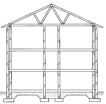
Although beams and slabs with simple, solid cross-sections are normally used for the floor elements of loadbearing-wall buildings, because the spans are usually short (see Section 6.2), axially stressed elements in the form of triangulated trusses are frequently used to form the horizontal elements in the roof structures. The most commonly used lightweight roof elements are timber trusses (Fig. 5.8) and lightweight steel lattice girders.
The discontinuous loadbearing wall configuration is a very basic form of structure in which the most elementary types of bending (i.e. non-form-active) elements, with simple, solid cross-sections, are employed. Their efficiency is low and a further disadvantage is that the requirements of the structure impose fairly severe restrictions on the freedom of the designer to plan the form of the building – the primary constraints being the need to adopt a multi-cellular interior in which none of the spaces is very large and, in multi-storey buildings, a plan which is more or less the same at every level. The structures are straightforward and economical to construct,
however. 49
Fig. 5.4 In the cross-section of a post-and-beam loadbearing masonry structure the reinforced concrete floors at the first- and second-storey levels span one way between the outer walls and central spine walls. Timber trussed rafters carry the roof and span across the whole building between the outer walls.
Where greater freedom to plan the interior of a building is required or where large interior spaces are desirable, it is usually necessary to adopt some type of frame structure. This can allow the total elimination of structural walls,
50
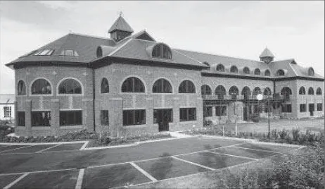
Fig. 5.6 Corinthian Court, Abingdon, UK; the Baron Willmore Partnership, architects; Glanville and Associates, structural engineers. The vertical structure of this three-storey office building, which measures 55 m by 20 m on plan and has few internal walls, is of loadbearing masonry. The floors are of reinforced concrete.
Fig. 5.7 In these arrangements the floor structures are two-way spanning reinforced concrete slabs. This allows more freedom in the positioning of loadbearing walls than is possible with one-way spanning timber or pre-cast concrete floors.
and large interior spaces can be achieved as well as significant variations in floor plans between different levels in multi-storey buildings.
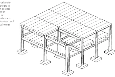
The principal characteristic of the frame is that it is a skeletal structure consisting of beams supported by columns, with some form of slab floor and roof (Fig. 5.9). The walls are usually non-structural (some may be used as vertical-plane bracing) and are supported entirely by the beam-column system. The total volume which is occupied by the structure is less than with loadbearing walls, and
individual elements therefore carry larger areas of floor or roof and are subjected to greater amounts of internal force. Strong materials such as steel and reinforced concrete must normally be used. Skeleton frames of timber, which is a relatively weak material, must be of short span (max 5 m) if floor loading is carried. Larger spans are possible with single-storey timber structures, especially if efficient types of element such as triangulated trusses are used, but the
maximum spans are always smaller than those of equivalent steel structures.
The most basic types of frame are arranged as a series of identical ‘plane-frames’ of
rectangular geometry2, positioned parallel to one another to form rectangular or square column grids; the resulting buildings have forms which are predominantly rectilinear in both plan and cross-section (Fig. 5.9). A common variation of the above is obtained if triangulated elements are used for the horizontal parts of the structure (Fig. 5.10). Typical beam-column arrangements for single and multi-storey frames are shown in Figs 5.11 to 5.13; note that systems of primary and secondary beams are used for both floor and roof structures. These allow a reasonably even distribution of internal force to be achieved between the various elements within a particular floor or roof structure. In Fig. 5.12, for example, the primary beam AB supports a larger area of floor than the secondary beam CD, and therefore carries more load. The magnitudes of the internal forces in each are similar, however, because the span of AB is shorter3.
51
Fig. 5.9 A typical multi-storey frame structure in which a skeleton of steel beams and columns supports a floor of reinforced concrete slabs. Walls are non-structural and can be positioned to suit space-planning
requirements.
2 A plane-frame is simply a frame with all elements in a single plane.
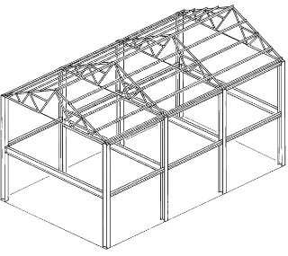
Fig. 5.10 In this steel frame, efficient triangulated elements carry the roof load. Floor loads are supported on less efficient solid-web beams with I-shaped ‘improved’ cross-sections.
Fig. 5.12 Typical floor layouts for multi-storey steel frames.
Fig. 5.11 A typical arrangement of primary and secondary beams in a single-storey steel frame. All beams have ‘improved’
triangulated profiles.
52
Skeleton frames can be of either the discontinuous or the continuous type. Steel and timber frames are normally discontinuous and reinforced concrete frames are normally continuous. In fully discontinuous frames all the joints between beams and columns are of the hinge type (Fig. 5.14). This renders the basic form unstable and reduces its efficiency by isolating elements from each other and preventing the transfer of bending moment between them (Fig. 5.15 – see also Appendix 3). Stability is provided in the discontinuous frame by a separate bracing system, which can take a number of forms (see Figs 2.10 to 2.13). The need both to ensure stability and to provide adequate support for all areas of floor with hinge-joined elements normally requires that discontinuous frames be given regular geometries (Fig. 5.16).
If the connections in a frame are rigid, a continuous structure normally results which is both self-bracing and highly statically
indeterminate (see Appendix 3). Continuous frames are therefore generally more elegant than their discontinuous equivalents; elements are lighter, spans longer and the absence of vertical-plane bracing allows more open interiors to be achieved. These advantages, together with the general planning freedom
53
Fig. 5.14 A typical arrangement for a discontinuous multi-storey frame. All beam end connections are of the hinge type as are the column joints, which occur at alternate storey levels. The arrangement is highly unstable and requires a separate bracing system to resist horizontal load.
Fig. 5.16 Single-storey steel framework. Although some of the structural connections here are rigid, the majority of the horizontal elements have hinge joints. The regularity of the arrangement and the presence of a triangulated bracing girder in the horizontal plane (top left) are typical of a discontinuous framework. (Photo: Photo-Mayo Ltd)
Fig. 5.15 Preliminary analysis of a
54
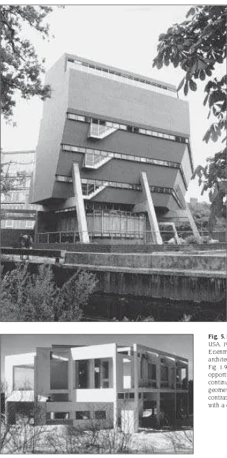
Fig. 5.17 Florey Building, Oxford, UK, 1971; James Stirling, architect. The Florey Building, with its crescent-shaped plan, complex cross-section and glazed wall, illustrates how the geometric freedom made possible by a continuous frame of in situ
concrete can be exploited. (Photo: P. Macdonald)
which a high degree of structural continuity allows, means that more complex geometries than are possible with discontinuous structures can be adopted (Figs 5.17, 5.18 and 1.9).
Due to the ease with which continuity can be achieved and to the absence of the ‘lack-of-fit’ problem (see Appendix 3), in situreinforced
concrete is a particularly suitable material for continuous frames. The degree of continuity which is possible even allows the beams in a frame to be eliminated and a two-way spanning slab to be supported directly on columns to form what is called a ‘flat-slab’ structure (Figs 5.19 and 7.33). This is both highly efficient in its use of material and fairly simple to construct. The Willis, Faber and Dumas building (Figs 1.6, 5.19 and 7.37) has a type of flat-slab structure and this building demonstrates many of the advantages of continuous structures; the geometric freedom which structural continuity allows is
particularly well illustrated.
5.3 Semi-form-active structures
Semi-form-active structures have forms whose geometry is neither post-and-beam
nor form-active. The elements therefore contain the full range of internal force types (i.e. axial thrust, bending moment and shear force). The magnitudes of the bending moments, which are of course the most difficult of the internal forces to resist
efficiently, depend on the extent to which the shape is different from the form-active shape for the loads. The bending moments are significantly smaller, however, than those which occur in post-and-beam structures of equivalent span.
Semi-form-active structures are usually adopted as support systems for buildings for one of two reasons. They may be chosen because it is necessary to achieve greater efficiency than a post-and-beam structure would allow, because a long span is involved or because the applied load is light (see Section 6.2). Alternatively, a semi-form-active structure may be adopted because the shape of the building which is to be supported is such that neither a very simple post-and-beam structure nor a highly efficient fully form-active structure can be accommodated within it.
Figure 5.20 shows a typical example of a type of semi-form-active frame structure which is frequently adopted to achieve long spans in
conjunction with light loads. It can be 55