RECONSTRUCTION OF FAÇADES IN POINT CLOUDS FROM
MULTI-ASPECT OBLIQUE ALS
Sebastian Tuttas*, Uwe Stilla
Photogrammetry and Remote Sensing, Technische Universität München, 80290 München, Germany - [email protected], [email protected]
Commission III, WG III/4
KEY WORDS: Laser Scanning, Point Cloud, Reconstruction, Building, Urban
ABSTRACT:
In this paper an approach is described which allows the reconstruction of windows in façades from airborne laser scanning (ALS) data taken in oblique view. A challenge is the sparse sampling of the façades by ALS compared to terrestrial laser scanning. In a first step windows are detected by a search for measurements of laser pulses which pass the windows (voyeur effect) and reflect behind the façade (indoor points). For a general study exploiting this side effect two different cases are considered: (i) a city model with faces of the façade is available and the point cloud has to be co-registered, (ii) a city model is not available and façade planes has to be automatically derived from the point cloud itself. Then, in both cases indoor points are mapped to a raster on the façade plane to accumulate hypotheses for the position of windows. Based on the points lying around these positions rectangular windows are reconstructed on the façade wall. Finally, the outlines of the windows are adapted by considering all windows of one façade. For a selection of eleven façades a quality analysis was performed showing a detection rate of 67%, a false alarm rate of 9% and an error of window sizes varying from a few centimeter to about one meter.
1. INTRODUCTION 1.1 Motivation
Façade information for city modelling is often derived from terrestrial images, static terrestrial laser scanning (TLS) or mobile terrestrial laser scanning (MLS). Due to the limited access to private property terrestrial acquisitions in inner city areas show typically only façades visible from public ground like streets or squares. For some tasks, e.g. navigation, a partial building mapping seems to be sufficient, but other tasks, e.g. thermal inspection, require information about the entire building hull. While an increase market for oblique (45 degree) airborne imagery can be observed, little attention has been paid to airborne laser scanning (ALS) in oblique view (Hebel & Stilla, 2010). Co-registered point clouds taken from four orthogonal viewing directions can provide for many cities a nearly complete 3D mapping of building hulls. An example of such a point cloud can be seen in Figure 1.
1.2 Related Work
Approaches for window detection and reconstruction from TLS are often based on the assumption that windows are represented as holes in the point cloud. In Pu & Vosselman (2009) and Boulaassal et al. (2011) edge points of the windows are detected by searching for long triangle edges in a mesh created from the point cloud. A line is fitted to the detected edge points. Martínez et al. (2012) segment a façade by analysing the histogram of points in façade normal direction, looking for local minima and maxima. The boundaries of meshes of the segmented parts are used as façade contours. In Wang et al. (2012) the edge points are determined by analysing the local neighbourhood of the points. Then a plane-sweeping approach is used to create a vertical and a horizontal profile of the edge points. The maxima represent the window edges. Regularities of window arrangement are
* Corresponding author.
implicitly used. Mesolongitis & Stamos (2012) assume that the windows of a single façade are arranged in one or more periodic structures. They fit a grid structure to a binary image, which was created from the positions of holes in the point cloud. The approach of Schmittwilken & Plümer (2010) differs from the aforementioned approaches since it is based on trained shape parameters for the façade elements which are used for classification and reconstruction. Also the image based approach from Reznik & Mayer (2008) utilizes training data for the detection of windows. They also use the assumption that windows are arranged in periodic structures. Schindler & Bauer (2003) calculate point clouds from façade images. Window edges are derived from the point cloud using a plane-sweeping approach to extract points not lying on the main planes. The resulting window outlines are refined after backprojecting them to the images. The work of Lee & Nevatia (2004) aims on the integration of windows into existing 3D building models. For the reconstruction of the windows they use vertical and horizontal histograms calculated from edges in façade textures. The topic of evaluation of results of façade reconstruction from TLS is covered by Landes et al. (2012).
The introduction of formal grammars can consider local relations and exploit regular structures. In the approach of Becker (2009) window structures which are derived from TLS and images are synthetically inserted into façade parts which are not covered by the data. Also Ripperda & Brenner (2009) use a grammar based reconstruction process for analysis of image and range data. Approaches with shape grammars which are applied on image data (normally rectified) can be found in combination with supervised classification using random forests (Teboul et al. 2010, Riemenschneider et al. 2012) or symmetry detection using mutual information and façade splitting based on edge information (Müller et al. 2007).
The approaches mentioned before use features (e.g. edges) from images or laser point clouds which require a proper sampling of ISPRS Annals of the Photogrammetry, Remote Sensing and Spatial Information Sciences, Volume II-3/W3, 2013
the façades. The ALS point cloud depicted in Fig. 1 shows only a sparse sampling of the façades (e.g., see building on the left) compared to point clouds taken by a terrestrial acquisition. To cope with this challenge we exploit in our work indoor points which arise from laser pulses passing the windows and reflected behind the façade in the rooms. We call this the 'voyeur effect'. The low reflection of laser pulses from windows was also subject of earlier investigations applying a full waveform analysis (Yao
& Stilla, 2010). In this paper we investigate to which extends a window detection based on the mentioned effect performs using an oblique ALS data set and how accurate the windows can be reconstructed based on the sparse sampling. We show here in extension to earlier work (Tuttas & Stilla, 2012) a more detailed evaluation and two different reconstructions assuming that (i) a city model is given and (ii) a city model is not given.
Figure 1. Point cloud from multi-aspect oblique airborne laser scanning (height coded by colour)
2. METHOD 2.1 Overview
The method shown in this paper has to cope with point clouds acquired by oblique multi aspect ALS showing different point densities on surfaces. The scan pattern on a façade depends on the helicopter’s trajectories and the orientation of the façade. While many roof faces are scanned four times during a flight in a cross pattern (four aspects), façades are captured only once or twice (see scan lines in Figures 1 and 2a). Due to these conditions and a relatively sparse sampling it is difficult to detect windows by a search for missing points in the façade plane or points close behind the plane on the window as proposed by other authors.
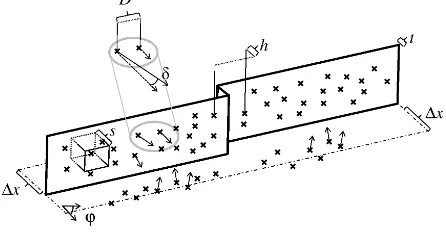
Figure 2. Point distributions at a façade for oblique view ALS showing the ‘voyeur effect’. a) section of Fig. 1, b) acquisition geometry (blue: façade points, red: indoor points), c) accumulated points in a side view, d) accumulated points in a top view
Instead of this strategy 3D points are searched which result from reflections in the rooms (floor, desk, bed, etc. → voyeur effect) (see Figure 2).
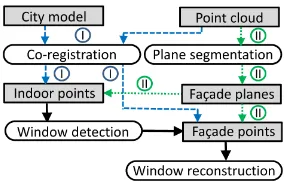
Before searching indoor points façade planes have to be determined. The plane segmentation proposed in Tuttas & Stilla (2012) and described in Section 2.3 (now as coarse segmentation) was improved, because multiple façade parts with a small offset in façade normal direction led to false assignment of points to indoor points. In this paper two different ways to refine the selection of façade planes are considered: (i) the point cloud is co-registered to an existing city model, which is used to extract appropriate façade points, (ii) for the case that no city model is available a refined segmentation is proposed. Both possibilities are described in the following sections (2.2 for case I and 2.3 for case II). The window reconstruction is described in Section 2.4, which is for both the same. The dependencies of all processing steps are shown in the following flowchart (Figure 3).
Figure 3. Processing steps (dashed: using model and point cloud (I); dotted: using only point cloud (II))
2.2 Coregistration of point cloud and city model
For the coregistration of model and point cloud a plane based approach shown in Hebel & Stilla (2012) is used. The transformation parameters are calculated using the roof planes in the model and their corresponding planes estimated from the point cloud. A system of linear equations which are set up based on conditions on the plane normals are used for the calculation. ISPRS Annals of the Photogrammetry, Remote Sensing and Spatial Information Sciences, Volume II-3/W3, 2013
The city model used here was extracted from aerial stereo imagery. Because of this the building size is determined by the roof shapes. For many buildings the façade plane itself is behind the eave, what is correctly mapped by the laser scanner but is not represented by the model. Because of this only the roof planes are used for the co-registration. It is assumed that model and point cloud are coarse pre-aligned. The following steps are performed for every model plane which are not vertical (i.e. roof planes): - Selection of points which lie in front and behind the plane
within the distance a.
- Fitting of a plane with RANSAC to the selected points. To ensure correspondence between model and fitted plane only samples are accepted which fulfill the following criteria: The angle γ between the normal of the plane calculated from the sample points and the normal of the model plane has to be smaller than a threshold.
Plane correspondences having large deviations in distance of the centroids (e.g. if a plane is not completely covered with points) are rejected. Since we assume a shift between model and point cloud we cannot assure that we get all points corresponding to the planes. Because of this the presented procedure is performed iteratively until the mean distance of the same points in two successive steps fall below a threshold d.
2.3 Plane detection
The detection of façade planes consists of a coarse and a fine processing step. The used parameters are shown in Figure 4, the chosen values are given and motivated in Section 3.3. The coarse step is a region growing based on the angle threshold δ for the normal of each point and the threshold D for the distance of the points. This is done only for points which normals are approximately vertical (using a threshold ϕ).
Figure 4. Parameters used for plane segmentation
After this step each detected plane is analysed, if it should be splitted into multiple segments for an improved indoor point identification. For that all points from the complete point cloud lying within ∆x in front or behind the detected planes are used. This threshold is not critical, it has only to be ensured that all façade and indoor points will be processed. These points are segmented again but now the segmentation is based on a parameter which uses the horizontal distance h between the points in façade normal direction. For every point a bounding box perpendicular to the façade normal direction with the size s is used to get its neighbours. Points within this bounding box are fused to one segment if the distance h is smaller than a threshold. The best main façade plane points in one segment are finally selected by RANSAC. The parameter t is used for the decision if a point is an inlier (i.e. a façade point). As indoor points all points are chosen which are behind the façade point with the smallest x-coordinate in a façade x-coordinate system whereby the x-axis points in the direction of the façade normal. The reconstructed planes are calculated from the maximum extent of the respective façade points.
2.4 Window Detection and Reconstruction
Using the refined plane segmentation the indoor points can easily extracted (case II). Using the model (case I) the points are selected as indoor points if they are lying behind the points which are belonging to the façade wall. According to the procedure described in Tuttas & Stilla (2012) for each indoor point the ray from the corresponding sensor position is intersected with the façade plane to receive points for the further window reconstruction. For every façade a binary image is created. In this image every pixel is set to 1 if at least one indoor points exists at this position, otherwise it is set to 0. After that the correlation sums of it with a horizontal and a vertical linear feature are calculated. The values of the correlation sum images are summed up in row and column direction, respectively. The combinations of all maxima are used as initial window positions. These initial window positions are used for the window reconstruction. For this processing step, not the indoor points but the façade points are used, which means that now the windows shall be represented as holes. Based on the initial position a rectangle is fitted to that hole. Because of the low point density the window edges are not represented clearly in the point cloud. The consequence is that the window size varies between equal sized windows. Because of this the uncertainty of each window edge is modelled with a Rayleigh distribution. To calculate the final window edges the distribution functions are summed up in row and in column direction. For every window the closest maxima in the resulting functions for upper, lower, right and left edges to the original position is chosen as final window outline. That means, if neighbouring windows are of the same type, they contribute to a common final edge estimate, because they should support the same edge hypothesis. This method also allows different window sizes in one row or column if the respective edge deviates enough from the other windows.
Since the reconstruction is based on planes estimated from the façade points, the reconstructed windows lie on these planes, which are not completely equal to the model planes because of generalization effects. Thus the windows reconstructed from the approach using the city model are projected perpendicular on the respective model plane, using the normal direction of the point cloud plane.
3. EXPERIMENT 3.1 Data
The point cloud was generated from four flights of a helicopter in a cross pattern over the test area TUM in Munich, Germany (Hebel & Stilla, 2012). The city model was measured from aerial images.
3.2 Reconstruction using city model
For co-registration 323 roof planes were used. Using a threshold d = 10 cm five iterations were necessary for the co-registration. For the distance a = 5 m was chosen, which represents the accuracy which is at least expected from a coarse registration. The threshold for accepting a point as inlier during RANSAC was set to 10 cm for the determination of the façade plane in the point cloud. The city model together with the reconstructed windows can be seen in Figure 5.
3.3 Reconstruction using plane detection
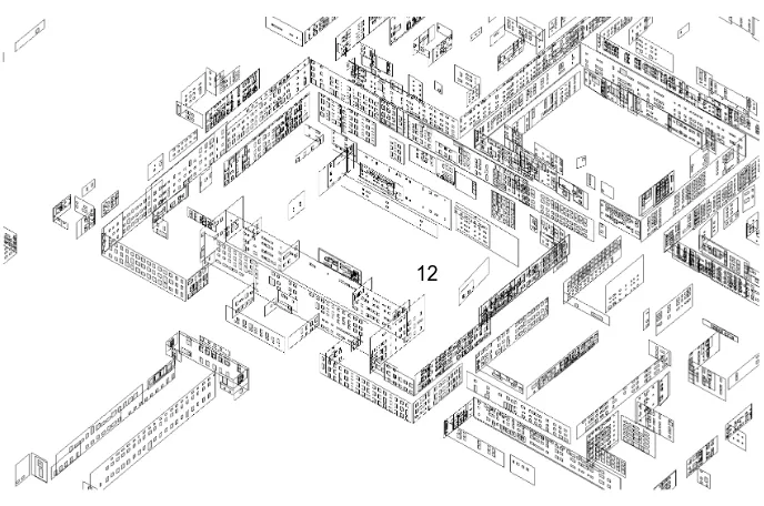
The final result for the detected planes can be seen in Figure 6. The chosen parameters are ϕ = 10°, D = 3 m and δ = 5° for the coarse segmentation step. For the fine segmentation step ISPRS Annals of the Photogrammetry, Remote Sensing and Spatial Information Sciences, Volume II-3/W3, 2013
∆x = 5 m, s = 2 m (this value has to be larger than the point distance and smaller than the width or height of the façade parts, which shall be split), h = 5 cm (this value represents the minimum
horizontal offset of two adjacent façades parts, which shall be split) and t = 20 cm are used.
Figure 5. Final result, showing the model with reconstructed windows (I)
Figure 6. Final result with detected façade planes and reconstructed windows (II)
3.4 Evaluation of window detection
Due to the limited length of the paper we focus on the results obtained for case I (with city model). A quantitative evaluation for window detection was performed for the façades at the outer south and outer east sides of the TUM building. In Figure 7 and Figure 8 the reconstructed windows are shown together with textures for these façades. For reconstruction of these façades about 22000 laser points were analysed, which means there is a
point density of 3.3 points per m2. An example for the distribution around a window shows Figure 9a. In Table 1 the detection results are given for every façade part individually. A true positive was counted if the centre of the reconstructed window is inside the true window area. The underlying textures were not taken at the same time, but should give an idea about the appearance of the façades. Because of errors in co-registration of textures to the model the evaluation was done manually based on the point cloud itself. A detection rate of 67% could be achieved, 9
10
11 1 - 8
12
12 1
8
having 9% false alarms. In both case the very small windows at the top of facades 8, 9 and 11 are considered, which explains the detection rate of only 75 % for these façade, even it seems that all window have been detected.
3.5 Evaluation of window reconstruction
For the façades 1 to 8 the reconstruction result was also evaluated using the window sizes. For that the reference size, i.e. window
height and width, of each window was measured manually in orthophotos of the façades, which were derived from a bundle block of façade images. For the analysis all 116 correct detected window of façades 1 to 8 were used. The measure here is the deviation from the reference size and not the absolute coordinates. The magnitude of the deviation for window height and width for all windows is shown in Figure 9b and 9c. The mean value over all deviations is 0.50 m for the height and 0.41 m for the width.
1 2 3 4 5 6 7 8 Figure 7. Textures and reconstructed windows for façade parts 1 to 8 (from left to right)
9 10 11 Figure 8. Textures and reconstructed windows for façade parts 9 to 11 (from left to right)
Number 1 2 3 4 5 6 7 8 9 10 11 ΣΣΣΣ
GT 14 42 9 9 9 24 21 16 60 57 60 321
D 6 56 10 6 6 22 18 12 45 9 45 235
TP 2 42 9 6 6 21 18 12 45 8 45 214
FP 4 14 1 0 0 1 0 0 0 1 0 21
FN 12 0 0 3 3 3 3 4 15 47 15 107
DR 0.14 1.00 1.00 0.67 0.67 0.88 0.86 0.75 0.75 0.14 0.75 0.67
FR 0.67 0.25 0.10 0.00 0.00 0.05 0.00 0.00 0.00 0.11 0.00 0.09
Table 1. Detection rate (DR) and false alarm rate (FR) for the facades shown in Figure 7 and Figure 8 (GT= Ground Truth, D = total detections, TP = True Positives, FP = False Positives, FN = False Negatives)
a) b) c)
Figure 9. Single window with surrounding façade points from Façade 2 (a), absolute value of deviation of window height (b) and width (c) for windows from Figure 7
4. DISCUSSION AND OUTLOOK
The quality analysis of the selected 11 façades shows an overall detection rate of 67% and a false alarm rate of 9%. One assumption for the detection and reconstruction of the windows is the planarity of the façade. Consequently a curved wall like façade 12 in Figure 7 and 8 was not reconstructed and windows
were not detected. For considering also the few non-planar façades additionally curved models (e.g. cylindrical) has to be introduced and fitted to the point cloud. In case that a city model is available arbitrary façades structure can be easily considered assuming that these structures are captured by the model. An additional assumption is that the surrounding wall area exceeds the window area. This assumption is given for most façades, but ISPRS Annals of the Photogrammetry, Remote Sensing and Spatial Information Sciences, Volume II-3/W3, 2013
locally violated for the upper window rows of façade 10 in Figure 8. Furthermore, this problem occurs at glass façades, because of the difficulty to estimate the main façade plane. However, in this case the general question comes up: “What is a window?” The error of window sizes show strongly varying values from a few centimeter to about one meter, what is dependent on the local point density and the amount of equal windows which occur in the process for the estimation of the window outlines. But still same sized windows show variation in some cases which means that the regularization does not work for all cases.
From the experiments it can be stated that the results are better the larger and the more equal the windows are and the more regular the arrangement of the window is. For applications where the general appearance of a city model containing façade structures is in focus and the individual positions and sizes of windows are of minor interest, rule based approaches can improve the detection of regular window structures.
5. SUMMARY
In this paper an approach for the generation of façade planes with windows and alternatively the enrichment of an existing city model with windows from a multi-aspect oblique view ALS point cloud is described. From the investigations and results in Figure 5 and 6 it can be seen that the described ‘voyeur effect’ is not only an exceptional observation for some few windows, but is given for many windows in the test area and can be exploited for façade reconstruction. The evaluation shows that the detection has a very low false alarm rate. The estimated window sizes are more or less rough, but allow an estimate about the ratio of window to wall area. In contrast to TLS and MLS large inner city regions with inaccessible areas and not observable façades can be mapped and analysed.
ACKNOWLEDGMENTS
This work was partly supported by DFG-Projekt STI 545/6-1 „Entwicklung eines automatisierten Verfahrens zur Baufort-schrittskontrolle auf Basis der Integration von Punktwolken-interpretation und 4D-Bauwerksmodellierung“. The authors want to thank Dr. M. Hebel (Fraunhofer IOSB) for providing the co-registered point cloud.
REFERENCES
Becker, S., 2009. Generation and application of rules for quality dependent façade reconstruction. ISPRS Journal of
Photogrammetry and Remote Sensing, 64 (6), pp. 640-653.
Boulaassal, H.; Landes, T., Grussenmeyer, P., 2011. 3D modelling of façade features on large sites aquired by vehicle based laser scanning. In: Archives of Photogramm., Cartography and Remote Sens. edited by Polish Society for Photogrammetry
and Remote Sensing. Vol. 22, pp. 215-226.
Hebel, M., Stilla, U., 2012. Simultaneous calibration of ALS systems and alignment of multiview LiDAR scans of urban areas.
IEEE Transactions on Geoscience and Remote Sensing, 50(6),
pp. 2364-2379.
Landes, T., Boulaassal, H., Grussenmeyer, P., 2012. Quality Assessment of Geometric Façade Models Reconstructed From TLS Data. The Photogrammetric Record, 27(138), pp. 137-154.
Lee, S.C., Nevatia, R., 2004: Extraction and integration of window in a 3D building model from ground view images. In:
Computer Vision and Pattern Recognition (CVPR), IEEE
Conference on Washington, DC, USA, Vol. 2, pp. 113-120.
Martínez, J., Soria-Medina, A., Arias, P., Buffara-Antunes, A. F., 2012. Automatic processing of Terrestrial Laser Scanning data of building façades. Automation in Construction, 2012(22), pp. 298-305.
Mesolongitis, A., Stamos, I., 2012. Detection of windows in point clouds of urban scenes. In: Computer Vision and Pattern Recognition Workshops (CVPRW), IEEE Computer Society
Conference on, pp. 17-24.
Müller, P., Zeng G., Wonka P., Van Gool L., 2007. Image-based procedural modeling of facades. ACM Trans. Graph. 26(3), pp. 85/1–85/9.
Pu, S., Vosselman, G., 2009. Knowledge based reconstruction of building models from terrestrial laser scanning data. ISPRS
Journal of Photogrammetry and Remote Sensing, 64(6), pp.
575-584.
Reznik S., Mayer H., 2008. Implicit shape models, self-diagnosis, and model selection for 3D façade interpretation. PFG
Photogrammetrie, Fernerkundung, Geoinformation, 2008(3),
pp. 187-196.
Riemenschneider, H., Krispel, U., Thaller, W., Donoser, M., Havemann, S., Fellner, D., Bischof, H., 2012. Irregular lattices for complex shape grammar facade parsing. In: Computer Vision
and Pattern Recognition (CVPR), IEEE Conference on, pp.
1640-1647.
Ripperda, N., Brenner, C., 2009. Application of a Formal Grammar to Facade Reconstruction in Semiautomatic and Automatic Environments. In: Proceedings of 12th AGILE
Conference on GIScience, Hannover, Germany, 2009.
Schindler, K., Bauer J., 2003. A model-based method for building reconstruction. In: Higher-Level Knowledge in 3D Modeling and Motion Analysis. HLK 2003. First IEEE
International Workshop on, pp. 74-82.
Schmittwilken, J., Plümer, L., 2010. Model-based reconstruction and classification of façade parts in 3D point clouds. In: Int.
Archives Photogramm. Remote Sens. Spatial Inf. Sci.,
Sainte-Mandé, France, Vol. XXXVIII, Part 3A, pp. 269-274.
Teboul, O., Simon, L., Koutsourakis, P., Paragios, N. (2010). Segmentation of building facades using procedural shape priors.
In: Computer Vision and Pattern Recognition (CVPR), IEEE
Conference on, pp. 3105-3112.
Tuttas, S., Stilla, U., 2012. Reconstruction of rectangular windows in multi-looking oblique view ALS data. ISPRS Ann.
Photogramm. Remote Sens. Spatial Inf. Sci., I-3, pp. 317-322.
Wang, R., Ferrie, F., Macfarlane J., 2012. A Method for Detecting Windows from Mobile LiDAR Data.
Photogrammetric Engineering and Remote Sensing, 78(11),
pp. 1129-1140.
Yao, W., Stilla, U., 2010. Mutual Enhancement of Weak Laser Pulses for Point Cloud Enrichment Based on Full-Waveform Analysis. IEEE Transactions on Geoscience and Remote
Sensing, 48(9): 3571-3579