A METHOD TO ACHIEVE LARGE VOLUME, HIGH ACCURACY
PHOTOGRAMMETRIC MEASUREMENTS THROUGH THE USE OF AN ACTIVELY
DEFORMABLE SENSOR MOUNTING PLATFORM
B. Sargeanta, S. Robsona, E.Szigetib, P.Richardsonb, A.El-Nounub, M.Raflab
aDept. of Civil, Environmental and Geomatic Engineering, University College London, Gower Street, London, WC1E 6BT UK - [email protected]
bAirbus, Pegasus House, Aerospace Avenue, Filton, Bristol, BS34 7PA
Commission V, WG V/1
KEY WORDS: Photogrammetry, 6DoF tracking, Digital Image Correlation, Robotics
ABSTRACT:
When using any optical measurement system one important factor to consider is the placement of the sensors in relation to the workpiece being measured. When making decisions on sensor placement compromises are necessary in selecting the best placement based on the shape and size of the object of interest and the desired resolution and accuracy. One such compromise is in the distance the sensors are placed from the measurement surface, where a smaller distance gives a higher spatial resolution and local accuracy and a greater distance reduces the number of measurements necessary to cover a large area reducing the build-up of errors between measurements and increasing global accuracy. This paper proposes a photogrammetric approach whereby a number of sensors on a continuously flexible mobile platform are used to obtain local measurements while the position of the sensors is determined by a 6DoF tracking solution and the results combined to give a single set of measurement data within a continuous global coordinate system. The ability of this approach to achieve both high accuracy measurement and give results over a large volume is then tested and areas of weakness to be improved upon are identified.
1. INTRODUCTION
Obtaining the best results from any optical metrology system requires optimal positioning of each sensor or sensors with respect to the workpiece. When deciding where to position each sensor, its capabilities must be understood with respect to the metrology requirement. Compromises usually have to be made. One such compromise might be in the distance at which systems of sensors are placed from the object of interest. For example, for wide angle imaging systems, the further from the object the sensors are placed the wider the region that can be observed. Conversely the closer sensors are placed, the narrower the region observed, the greater the accuracy and spatial resolution that can be obtained (Luhmann, 2011). Additionally the object may deform or move over the time it is under observation, and so the field of view might need to be adapted to cover the whole area in which data is to be gathered.
Use of a mobile platform allows sensor positioning to be optimised during data capture. For example, a mobile platform allows for the sensor to surface distance to be reduced enabling higher accuracy measurements in combination with platform motion to cover larger objects and volumes. One drawback is that this process can be slow if a large volume is to be covered at a high level of detail and large surfaces would require a very large number of localised signalised points to enable registration of multiple image sets as the sensor platform moves imperfectly across the surface. A potential solution is to synchronously track the position of the platform during acquisition so that data captured at different points can be quickly combined and propagation of errors can be avoided.
This work proposes and evaluates an application of this solution using several low cost photogrammetric imaging sensors attached to a constantly deforming flexible robotic platform.
1.1 Photogrammetry
The discussion in this paper regards photogrammetry as a passive optical metrology method which uses optical sensors to capture images of the measurement subject and then extracts positional data about points on the object. This works by uniquely identifying features within multiple images and using the position of these features within the 2D images to geometrically calculate their positions in 3D space. Whilst this approach can be used to accurately reconstruct shape, measurements made using photogrammetric approaches are inherently scale-less. However several methods of adding known distances to scale the data gathered are available. For example, stereo photogrammetry uses two sensors with a known, constant inter-sensor distance and orientation, scale can then be derived from the relative position of points in images from both sensors (Ahmadabadian et al., 2013), (King, 1993). The stereo principle can be expanded to arrays of more than two sensors.
1.1.1 Digital Image Correlation
Digital Image correlation (DIC) is an application of the photogrammetric technique which aims to uniquely identify a large number of points on an object surface across multiple images and thus determine the overall shape of the object across the entirety of the region of interest(Anuta, 1970), (Keating et al., 1975). With a sufficiently textured surface this approach can be used directly, however it is often desirable to apply a specular pattern to the object being measured so as to ensure full coverage of the surface. The quality of results that can be The International Archives of the Photogrammetry, Remote Sensing and Spatial Information Sciences, Volume XLI-B5, 2016
obtained through this approach are highly determined by the relative size of the object being measured and the field of view of the sensors, such that the smaller the volume of interest the better the results that can be obtained.
1.1.2 Target Tracking
The basic principles of photogrammetry can be used to determine the location of points within a static scene, however this same approach can also be used to track moving objects by capturing synchronised image sequences from fixed sensors as the tracked object moves. Each set of simultaneous images is reconstructed as in the static case and the same points identified across the image sets, allowing their movement to be calculated. Where it is assumed that the points are all on a single rigid object, this information can be used to determine its movements and rotations through three dimensions giving 6 Degree of Freedom (6DoF) tracking (Sun et al., 2010), (Trieu et al., n.d.).
The use of photogrammetric targets or markers significantly enhances the ability of the system to accurately and continuously identify and coordinate the same unique location. Repeatedly finding a specific point on these targets can be done very accurately as they have a known shape which can be modelled, allowing for sub-pixel interpolation. One style of targets used are circular targets which define a point at the centre of the circle. A contrast in either brightness or colour between the circle itself and the area around it allows easy identification. Retro-reflective material can be used to give a very high contrast against a dark background by reflecting light from a light source near to the image sensor. Ideally this approach leads to a distributed level of brightness across the target with a very bright centre fading towards the edges, allowing for better determination of the central point (Shortis et al., 1994).
2. DESCRIPTION
This work was designed to investigate the feasibility of a method for combining the photogrammetric approaches of DIC and target-based 6DoF tracking to enable an automated approach to large volume high accuracy measurement using low-cost imaging sensors. To achieve this a robot-mounted stereo-camera system is to be positioned at an optimal range from the object of interest in order to make high accuracy surface measurements whilst a larger volume sensor array tracks the position of the robot platform to which the stereo-camera is attached. By combining measurements from these systems a point on the measured surface can be located within the larger volume. By repeating this process with the robot platform in multiple poses it is proposed that a compete model of a large object surface can be mapped at a high level of resolution and accuracy without the need for a separate registration and alignment step.
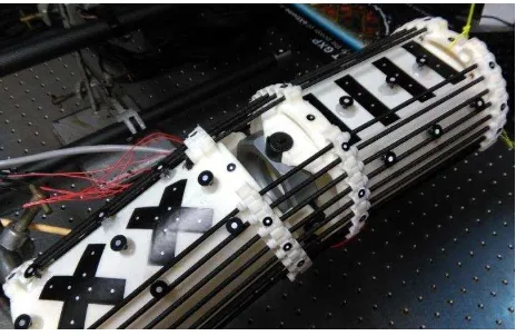
Figure 1. OC Robotics snake arm
In the experimental work behind this paper, the final design will be mounted to an OC Robotics snake arm (Figure 1). This robot has a design consisting of 12 short links with 2DoF joints between them creating a highly deformable 24 Degree of Freedom robot. This design enables a high degree of flexibility in deployment and positioning of the sensor platform. To test the design of a sensor system based around this robot a rapid-prototyped mock-up of a pair of snake arm links was used (Figure 2).
Figure 2. Prototype snake arm package design
To perform the target tracking the in-house VMS software is used for photogrammetric target coordination whilst DIC measurements are made using the VIC-3D software package (Correlated Solutions, 2016).
2.1 Prototype Design
Figure 3. Stereo-Camera mountings
A working prototype was developed and equipped with two low cost board level IDS uEye cameras with 5.4mm S-mount lenses. These cameras were mounted via lightweight, adjustable brackets designed to enable them to be positioned with an optimal stereo toe-in angle (Figure 3). These cameras, lenses and mounting brackets were all selected and designed to minimise weight as the OC Robotics snake arm has a limited lifting capacity. The cameras were also fitted with low cost LED light rings so as to provide more consistent lighting across the surface being measured. In order to achieve 6DoF tracking the platform also has a constellation of retroreflective targets on its upper surface.
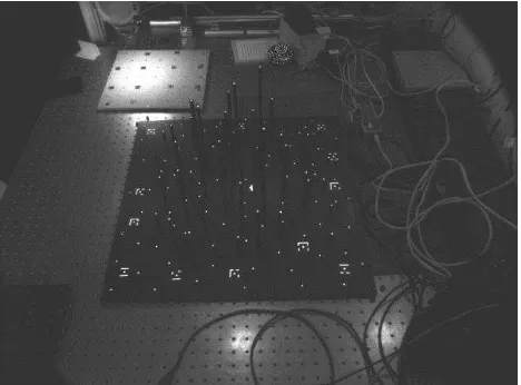
To track the movements of the stereo-camera platform a 6DoF tracking rig was produced (Figure 4) consisting of eight low cost IDS uEye cameras covering a 1m2 volume. These cameras were equipped with LED lighting rings so as to get the best return from the retroreflective targets.
Figure 4. 6DoF Tracking Rig
All ten cameras in use were also attached to a hardware trigger circuit which insures that images are captured from all cameras simultaneously. This is important as the platform may be unstable during data capture such that a delay between camera images can distort the results if they capture images of the platform in different positions.
2.2 Calibration
Before off the shelf cameras, such as those from IDS, can be used for photogrammetry they must be calibrated. The calibration process differs between the VMS and VIC-3D software package approaches but both require a rigid object equipped with circular targets in known positions to be imaged in several orientations by the cameras being calibrated. In both cases it is important to ensure that the entirety of the cameras field of view is covered. This process must be carried out both for the cameras in the tracking rig and those on the sensor platform. For the tracking rig a large plate with a number of raised retro-reflective targets filling a 3D volume “Manhattan Target” was used and a calibration was carried out in VMS. For the sensor platform a small stepped cone equipped with retro reflective targets was used for the VMS calibration and a flat board with black targets was used for the VIC-3D calibration. Both of these are shown in Figure 5 with a close up of the smaller calibration objects in Figure 6.
Figure 5. Large “Manhattan” calibration object
Figure 6. Small calibration objects
These set of calibrations determine the internal parameters of the individual cameras: the orientation of the digital image sensor to the lens and the distortions introduced by the lens. In addition the calibration gives the exterior orientation parameters for the cameras in the tracking rig and for the stereo-camera pair on the sensor platform, these define relative positions and rotations of individual cameras in each set of cameras.
In order for the sensor platform to be tracked, the position of the targets within the constellation on its upper surface had to be The International Archives of the Photogrammetry, Remote Sensing and Spatial Information Sciences, Volume XLI-B5, 2016
determined. These measurements were made photogrammetrically using a Nikon D700 DSLR camera with a pair of Brunson Scale bars equipped with photogrammetric targets to add known distances to the scene (Figure 7). Using the DSLR and scale bars ensures that this procedure gives higher accuracy positions for the targets compared to the accuracy obtainable using the cheaper cameras in the tracking rig. For the purpose of this paper, the DSLR data were considered as being true values against which measurements made during testing could be validated.
Figure 7. DSLR coordination of the Sensor Platform Target Constellation
In order for the intended procedure to be validated a test piece was made up consisting of a metal plate with both a textured pattern suitable for DIC and a number of circular retro-reflective targets applied to it. As with the targets on the sensor platform, the targets on the test piece were measured photogrammetrically using a Nikon D700 DSLR camera and a pair of Brunson Scale bars.
2.3 Test Procedure
To test the setup, the sensor platform was placed in 9 different positions to give 9 fields of view which tiled across the full surface of the test piece. In each position the images from both cameras on the sensor platform and all eight cameras on the tracking rig were simultaneously captured. These images were then processed in three ways so assess the capabilities of the system. Figure 8 shows the test plate and marks the areas covered by both cameras in each of the 9 positions.
Figure 8. Test plate with measurement positions
2.3.1 Direct Case
In the Direct Case, measurements from the sensor platform were used to determine the target positions on the work piece directly. Using the VMS bundle adjustment, the starting values for the positions of targets on the plate and the internal parameters found for the cameras in the calibration procedure were used to determine the orientation of the stereo-pair in each position. From these estimated camera orientations an intersection was used to estimate the coordinates of all visible targets for each stereo pair. In each platform position the results of this process were compared to the true positions for each point. Figure 9 shows the measurement platform above the test plate with lines of sight highlighted between each camera and two of the targets, allowing them to be directly measured.
Figure 9. Measurement process, Direct Case
2.3.2 Indirect Case
For the Indirect Case, the 6DoF tracking rig was used to determine the camera positions, rather than these being determined from the test plate. To achieve this, the position of the stereo cameras relative to the constellation of targets on the sensor platform has to be determined. This was done by taking camera orientations determined from the direct case and using the pre-calibrated tracking rig to simultaneously measure the orientation of the constellation of targets on the sensor platform. Determining the orientation of the target constellation is done The International Archives of the Photogrammetry, Remote Sensing and Spatial Information Sciences, Volume XLI-B5, 2016
by measuring each target separately followed by a least squares best fit of the true relative positions of the targets. The resulting transformation converts from the coordinate system used by the 6DoF tracking rig cameras to the coordinate system used by the measurement platform. From this a transformation was found to give the orientation of the stereo-camera pair relative to the platform coordinate system in any position.
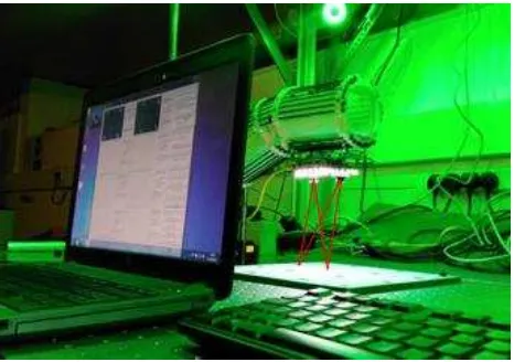
Figure 10. Measurement process, indirect case
For each of the 9 tiled positions the orientation of the sensor platform was found and this transformation was used to find the camera positions, which were then used to measure the targets on the test piece. In each platform position the results of this process were then compared to the true positions for each point. Similarly in each platform position the mean deviation of the targets, as measured by the tracking rig, from the “true” values as measured by the DSLR following the best fit were found. Figure 10 shows the full layout of the experiment and highlights the lines of sight between each camera in the tracking rig and two points on the sensor platform along with lines of sight between each camera on the platform and two of the targets on the test plate so as demonstrate how each direct measurement is made.
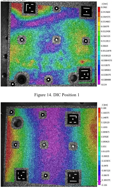
2.3.3 DIC
Finally DIC in VIC-3D is used to process each set of stereo images from the sensor platform. This gives a surface map of each section of the test piece with respect to the stereo camera system. The known camera positions and orientations from either the Direct or Indirect methods can then be used to generate a tiled surface map of the full test piece.
3. RESULTS
3.1 Direct Case
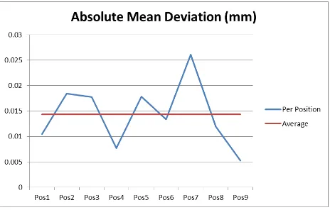
Figure 11 shows the absolute mean deviation across all visible points in each position when using the direct case.
Figure 11. Mean point deviations in mm, direct case
This shows that the system has the potential to achieve an average accuracy of 14µm and a worst case of 25 µm.
3.2 Indirect Case
Figure 12 shows the absolute mean deviation across all visible points on the sensor platform as measured by the 6DoF Tracking Rig.
Figure 12. Mean point deviations in mm on sensor platform
This shows that the 6Dof Tracking Rig is achieving an average point coordination accuracy of 17µm with a worst case of 20 µm.
Figure 13. Mean point deviations in mm, indirect case The International Archives of the Photogrammetry, Remote Sensing and Spatial Information Sciences, Volume XLI-B5, 2016
Figure 13 shows the absolute mean deviation across all visible position on the test piece giving a believable variation of 80µm across the plate. However all 8 other positions gave results results of the measurements to the sensor platform suggest that the 6DoF tracker can accurately determine the position of the sensor platform. However, when these results are combined in the direct case the results are rather poor.
The results from the DIC in the majority of the measured positions are highly indicative of a difference between the calibrated stereo-camera’s exterior orientation parameters and
the actual exterior orientation parameters during measurement. This suggests that after the first position the cameras began to move away from their initial calibrated condition, which would compromise the quality of the results. To see whether this is the case the relative camera orientations from each position, as found in the direct case, were compared to the camera orientations used for the indirect case. Figure 16 shows the relative RMS movement and rotation of the cameras when compared to the calibrated positions, alongside the accuracy of the indirect case results.
Figure 16. Deviation of relative camera position, in mm, and rotation, in degrees compared to mean point deviations in mm,
indirect case
This shows a very high correlation between the positions where the cameras have moved the most and the quality of the results, suggesting that the camera movements are to blame for the drop in the quality of the results.
5. CONCLUSION
These results show that low cost sensors in combination with careful photogrammetric technique are capable of achieving high accuracy close-range surface measurement and 6DoF tracking. However, variability in the indirect results suggests flexing of the prototype sensor platform, either due to flexibility in the rapid prototyped platform material or in the individual camera mountings is significant and is preventing simultaneous high accuracy full volume measurement. The drop in the quality of the results due to this small movement highlights the fact that when tracking a sensor platform in a targetless environment it is vital that relative sensor movement is physically prevented.
5.1 Future Work
An updated design of the system, including mounting onto the OC Robotics arm, is under construction. This, along with automated platform positioning, will enable measurements over a greater volume. The stiffer material of the robot arm compared to the rapid prototype should reduce much of the flexibility of the platform which degraded the indirect case. However the camera mounts are also being redesigned to remove points of flexibility, including the ability to adjust the camera angles, and to add stiffness between the two cameras, independent of the platform itself. Finally, the number of cameras is being increased to populate the entire robot arm. This will enable an entire cross section of a surface to be measured by capturing a large number of tiled field of views simultaneously and combining the measurements into a single coordinate system using the 6DoF tracking system.
6. REFERENCES
Ahmadabadian, A.H., Robson, S., Boehm, J., Shortis, M., 2013. Image selection in photogrammetric multi-view stereo methods for metric and complete 3D reconstruction, SPIE Optical Metrology 2013. International Society for Optics and Photonics, pp. 879107–879107.
Anuta, P.E., 1970. Spatial Registration of Multispectral and Multitemporal Digital Imagery Using Fast Fourier Transform Techniques. IEEE Transactions on Geoscience Electronics 8, 353–368.
Correlated Solutions, 2016. Correlated Solutions VIC-3DTM. VIC-3D. URL http://www.correlatedsolutions.com/vic-3d/ (accessed 4.17.16).
Keating, T.J., Wolf, P.R., Scarpace, F.L., 1975. AN
IMPROVED METHOD OF DIGITAL IMAGE
CORRELATION. Photogrammetric Engineering and Remote Sensing 41.
King, B.A., 1993. Optimisation of bundle adjustments for stereo photography. International Archives Of Photogrammetry And Remote Sensing 29, 168–168.
Luhmann, T., 2011. 3D imaging: how to achieve highest accuracy.
Shortis, M.R., Clarke, T.A., Short, T., 1994. Comparison of some techniques for the subpixel location of discrete target images.
Sun, P., Lu, N., Wang, B., Lin, Y., 2010. Multiview photogrammetry data registration by the way of stereovision movement tracking.
Trieu, H.T., Nguyen, T.L., Han, D., n.d. 6-DOF Measurement of a Vibrating Structure Using Digital Close-range Photogrammetry.