ANGLE COMPARISON AND DISTANCE COMPARISON
Liliana, Rudy Adipranata
Dosen tetap Fakultas Teknologi Industri, Jurusan Teknik Informatika Universitas Kristen Petra
Jl. Siwalankerto 121-131, Surabaya
Email: [email protected], [email protected]
ABSTRACT: In computer graphics applications, to produce realistic images, a method that is often used is ray tracing. Ray tracing does not only model local illumination but also global illumination. Local illumination count ambient, diffuse and specular effects only, but global illumination also count mirroring and transparency. Local illumination count effects from the lamp(s) but global illumination count effects from other object(s) too. Objects that are usually modeled are primitive objects and mesh objects. The advantage of mesh modeling is various, interesting and real-like shape. Mesh contains many primitive objects like triangle or square (rare). A problem in mesh object modeling is long rendering time. It is because every ray must be checked with a lot of triangle of the mesh. Added by ray from other objects checking, the number of ray that traced will increase. It causes the increasing of rendering time. To solve this problem, in this research, new methods are developed to make the rendering process of mesh object faster. The new methods are angle comparison and distance comparison. These methods are used to reduce the number of ray checking. The rays predicted will not intersect with the mesh, are not checked weather the ray intersects the mesh. With angle comparison, if using small angle to compare, the rendering process will be fast. This method has disadvantage, if the shape of each triangle is big, some triangles will be corrupted. If the angle to compare is bigger, mesh corruption can be avoided but the rendering time will be longer than without comparison. With distance comparison, the rendering time is less than without comparison, and no triangle will be corrupted.
Keywords: ray tracing, rendering, angle comparison, distance comparison, acceleration
BACKGROUND
Nowadays, computer graphic applications are used to model large and complex mesh objects. As complex and large objects, mesh objects need much time to render them. Many acceleration methods have been proposed to solve these problems, but the methods are used to lessen rays or faster intersection computations from first rays [6]. First rays cast from the camera to the scene. To create a realistic image, not only trace the first rays, but also the second rays. Second rays reflected or refracted from other object [4].
There are three kinds of acceleration techniques, fast intersection, fewer rays and generalized rays [8]. To make fast intersections, there are two different ways, fewer and faster ray-object intersection. Some methods used to accelerate rendering process are HBV (Hierarchical Bounding Volume), space subdivision and directional techniques.
By using HBV, there is a problem on tracing the ray from other object. This is because the ray comes from the hierarchy itself. Besides, there is a difficulty of bounding mesh object. If mesh is assumed as an object, the bound will be very large and not efficient in checking process. In other hand, if mesh is assumed as
some separate triangles, mirroring and transparency will be very difficult to model because each triangle will check other triangle as other object, not as itself. The other method, space subdivision, does not able to trace the second ray because subdivision created with camera’s position as its ray’s source point. The second ray does not come from the camera, but from other object.
With limited abilities of acceleration methods before, in this paper, new methods to reduce ray-object intersections will be explained. The main idea to reduce the intersections is checking objects which near the ray direction only. To know whether an object near enough or not from the ray, we can compute the angle and distance between the ray and the object.
ANGLE COMPARISON
In order to reduce the number of intersections, not all objects are checked. Only objects that have high probability intersect with the ray are checked. To predict which objects will intersect with the ray, firstly, the objects must be in the front of the ray, where the ray goes. This position is shown in Figure 1.
RAY
To determine whether an object in front of the ray or not, angle comparison can be used. The angle between the ray and the vector from the ray’s source to a point on the object called α. α must be less than or equal to 90°, so that it can be determined that the object is in front of the ray. Figure 2 shows the range of 90° surround the ray, the ray is the pivot.
The range 90° is too large because the ray will not intersect objects, which lay 90° from the ray. There is only one condition that α will be 90°, if the ray comes from the surface of the object toward the object. In a normal condition α must be smaller than 90°. Actually, there is no fix efficient angle’s measure-ment. This is because no fix distance between the point where the ray comes from and the object. The closer the distance, the bigger the angle (α).
To count α, scalar product can be used. The equation of scalar product can be seen in Equation 1 [1]. In the implementation, check the angle first. If the angle less or equal 90°, the triangle will check weather it intersects the ray or not.
The second method to reduce ray intersection checking is distance comparison. Distance compa-rison has main idea like angle compacompa-rison. If the distance between the ray and one point of three points in a triangle is close enough, the ray may intersect the triangle.
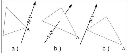
There are three major conditions where the ray intersects a triangle. The first condition (a) is the ray intersects a point in the triangle which will be checked its distance from the ray. If this condition happens, the distance will be zero. This is the best condition. The second condition (b) is the ray intersects any point in the triangle. The last condition (c) is the ray intersects a point farthest from point will be checked its distance. This is the worst condition. The three conditions are shown in Figure3.
From the worst condition, it can be determined that if the distance between a point in the triangle and the ray is not longer than the longest side of the triangle, it will have a high probability to intersect the triangle.
Figure 3. Three conditions of ray’s intersection
To measure the distance, the projection of a point onto a line (the arrow) is used, see Equation 2 [1]. Point (A) is one of the three points of the triangle and the arrow is the ray that intersects the triangle. d = | ray x A | / |A| (2)
In order to use distance comparison, pre-process-ing is needed.
EXPERIMENT
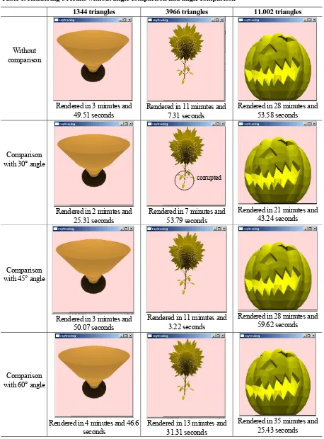
Table 1. Rendering’s results without angle comparison and angle comparison
1344 triangles 3966 triangles 11.002 triangles
Without comparison
Rendered in 3 minutes and 49.51 seconds
Rendered in 11 minutes and 7.31 seconds
Rendered in 28 minutes and 53.58 seconds
Comparison with 30° angle
Rendered in 2 minutes and 25.31 seconds
Rendered in 7 minutes and 53.79 seconds
Rendered in 21 minutes and 43.24 seconds
Comparison with 45° angle
Rendered in 3 minutes and 50.07 seconds
Rendered in 11 minutes and 3.22 seconds
Rendered in 28 minutes and 59.62 seconds
Comparison with 60° angle
Rendered in 4 minutes and 46.6 seconds
Rendered in 13 minutes and 31.31 seconds
Rendered in 35 minutes and 25.43 seconds
Table 2. Rendering’s results without distance comparison and with distance comparison
File’s name and properties Without distance comparison With distance comparison
Dolphin.obj 1692 triangles Longest side 34.0231
5.93684 neighbors
Rendered in 8 minutes and 33.44 seconds Rendered in 3 minutes and 42.39 seconds
Apel.obj 1704 triangles Longest side 24.8147
5.89619 neighbors
Rendered in 9 minutes and 35.84 seconds Rendered in 4 minutes and 8.61 seconds
R_Falke.obj 3574 triangles Longest side 54.1973
5.75215 neighbors
Rendered in 19 minutes and 46.61 seconds Rendered in 8 minutes and 38.49 seconds
Teapot.obj 3751 triangles Longest side 0.22526
5.69484 neighbors
Rendered in 18 minutes and 47.01 seconds Rendered in 8 minutes and 7.49 seconds
SunFlower.obj 3966 triangles Longest side 27.5898
3.48813 neighbors
As the result above, with 30° angle comparison, the rendering time is faster than without comparison, but in a worst condition, the mesh is corrupted. With 45° angle comparison, the mesh’s rendering has the same shape as the original mesh but the rendering time almost the same as without comparison.
The distance comparison is tested with five kinds of meshes. Each mesh has the same properties with the meshes above.
Each mesh rendered with distance comparison has 43.3%, 43.2%, 43.7%, 43.3%, and 43.3% rendering time than the rendering time without comparison.
CONCLUSIONS
Some conclusions that can be taken from this research are:
• For angle comparison, if the ray is checked with 60°, the rendering time will be longer than without comparison. It is caused by the time of counting the angle between two vectors. If the ray is checked with 30°, the rendering time will be faster but some triangles corrupted. So, this method is not a good way to faster rendering because of its predictable result.
• The results of original ray tracing’s rendering have the same image with those of rendering with distance comparison. No triangle corrupted. It has almost constant rendering time saving in various conditions, differences on amount of mesh’s triangles, on longest side and on the amount of neighbors.
REFERENCES
1. Anton, H., Elementary Linear Algebra. 7th ed. Drexel University. Philadelphia, 2000.
2. Buck, J., The Recursive Ray Tracing Algorithm. 1999.
3. Retrieved, from http://www.geocities.com/jamis-buck/raytracing.html#Introduction, May, 10, 2004.
4. Hill, F., Computer Graphics. Macmillan Publish-ing Company, New York, 1990.
5. Liliana. Creating Software to Visualize Trans-parent Object with Ray Tracing. Jurnal Informa-tika, vol 5 no 1. Petra Christian University. 2004, p. 1.
6. Magnor, M., Slusallek, P. Computer Graphics – Ray Tracing.
7. Retrieved from graphics.cs.uni-sb.de/Courses/ ss02/CG2/, May, 6, 2004.
8. Shoaff, W., Recursive Ray Tracing.