Fundus Imaging using Aplanat
Vishwanath Manik Rathod
A Thesis Submitted to
Indian Institute of Technology Hyderabad In Partial Fulfillment of the Requirements for
The Degree of Master of Technology
Department of Electrical Engineering
Acknowledgements
I would like thank my advisor Dr. Soumya Jana, Associate Professor, IIT Hy-derabad for giving me an opportunity to work under his guidance, supporting me throughout my M.Tech in getting good subject knowledge and providing many re-sources to learn. And also for being more than just a guide and giving many important life lessons. For preparing not only to be good engineer but more importantly to be a good human being. He always steered me in the right direction whenever he thought I needed it. I would like to thank IIT Hyderabad and L. V. Prasad Eye Institute for creating the opportunity and providing platform to pursue masters degree while working on a real life cutting edge problem. For giving me all facilities, opportunities and resources for completing my Masters and helping for me to grow as a human. I would like to thank iTREAT lab members at LV prasad. I am very thankful to Dr. Ashutosh Richariya, Sanjay Kumar, Dr. Kiran Kumar for consistent technical and non-technical guidance, and support. I would like to thank Professor Jeffrey M. Gordon, Ben-Gurion University of Negev for the thesis work idea and the necessary resources. I would like to thank my project partner Loke Sankrandan for all the brainstorming sessions and time to time solutions for many problems. For making me understand basic concepts and minute details . I would like to thank Vikram Goud for being a good friend, constant supporter and helping me throughout the degree in many ways and being there with me in all times for both professional and personal problems.
I would also like to take this opportunity to express my gratitude towards caring Seniors in Immersive Multimedia Technology(IMT) lab. There is a lot to learn from each and everyone. Their individual and team spirit, way to address the problem, helping nature has definitely influenced me in one or other way.
Finally, I must express my very profound gratitude to my parents for providing me with unfailing support and continuous encouragement throughout my years of study and through the process of researching and writing this thesis and even throughout the life for giving me complete freedom to pursue my dreams despite of many hurdles. This accomplishment would not have been possible without them. Thank you.
Dedication
This thesis is dedicated to:
My great parents, who never stop giving best of them in countless ways Great teachers and professors, who always steered me in right direction and taught
me the purpose of life
To all my family, the symbol of love and giving My friends who encourage and support me
Abstract
Retinal photography requires the use of a complex optical system called a fundus camera, capable of illuminating and imaging simultaneously. Because of restriction of aperture stop(pupil), available fundus imaging system suffer limited field of view. Hence peripheral area of retina remains undetected in traditional way. Also, system being prone to common aberrations always makes them to compromise with quality of image.
In this thesis we propose a system that uses an aberration free reflector called Aplanat instead of the conventional lens system for the fundus imaging. So Imaging optics will be based on reflection unlike the convectional system which uses lens system and hence refraction principle which results in very negligible aberrations. Also, small reflector size makes it a hand-held system with minimum complexity and power loss for illumination purpose. Working under thermodynamic limit and high numerical aperture makes it possible to inject maximum light at wide angle inside eye which abolish the necessity of mydriasis.
The optical system was designed in Zemax Optical Studio 15.5 in mixed sequential mode abilities by inserting aplanat as non sequential CAD object in sequential system comprised of eye and imaging sensor. CAD object was designed using Solid Edge ST8 using the Cartesian data points created in MATLAB. This solid object then imported to Zemax through CAD import ability. Present system propose 3 phase to image retina completely. A narrow throat aplanat for for some part close to optical axis leaving a small hole at optical axis. A wide throat aplanat to image peripheral area. a normal lens system that will cover the center hole. Exploiting overlapping part in the images from all the systems, stitching can be used to get the final complete image. Conjugate plane of retina found to be a curved surface and inside the aplanat which restricts us from using Zemax tool for the imaging purpose as it can not have of axis multiple sensor at desired location in align with conjugate of retina to sense ray bundle. Also, we loose smoothness and accuracy of reflector surface while im-porting the CAD object. So 3D image reconstruction of retina was performed in tool developed by project partner. All three phases covers almost 2000 wide field of retina
which counts for 87% of the retina surface. Exploiting overlapping part in the images from all the systems, stitching can be used to get the final complete image.
Contents
Declaration . . . ii
Approval Sheet . . . iii
Acknowledgements . . . iv Abstract . . . vi Nomenclature viii 1 Introduction 1 1.1 Ocular Fundus . . . 1 1.2 Fundus Imaging . . . 1
1.3 Motivation for Fundus Photography . . . 3
1.4 Historical Background . . . 4
1.5 Technical Aspects . . . 5
1.5.1 Fundus camera optics . . . 6
1.5.2 Commercially available fundus cameras . . . 9
1.6 Limitations . . . 12
1.7 Proposed Approach to Overcome Limitations . . . 13
2 Fundus Imaging using Aplanat 14 2.1 Proposed System . . . 14
2.2 Aplanat . . . 15
3 Equations for Aplanat 18 3.1 Fundamental Principles . . . 18 3.2 Derivation . . . 20 3.3 Special Cases . . . 23 3.4 Performance . . . 24 4 System Analysis 25 4.1 Methods . . . 25
4.2 Eye Model . . . 26
4.3 Aplanat reflector modelling and import to Zemax . . . 29
4.3.1 Getting Cartesian data points . . . 29
4.3.2 Using Solid Edge . . . 30
4.4 Optical System Design . . . 31
4.5 Results . . . 32
4.5.1 Conjugate plane of Retina . . . 32
4.5.2 Trade off . . . 33
4.5.3 Proposed solution . . . 34
4.5.4 Simulation results for normal lens system . . . 34
5 Conclusion and Future work 37 5.1 Conclusion . . . 37
5.2 Future work . . . 38
Chapter 1
Introduction
Eye is most important sensing organ of humans. It allows us to learn more about the surrounding world than we do with any of the other four senses. The eye allows us to see and interpret the shapes, colors, and dimensions of objects in the world by processing the light they reflect or emit. Humans perceive most of information though eye than any other sensing organ
1.1
Ocular Fundus
The term fundus refers to the base or bottom of something. In medicine, it is the part of any hollow organ (such as the uterus or the gall bladder or eyeball) that is the furthest from the opening, i.e. a general term for the inner lining of a hollow organ. The fundus of the eye is the inner surface of the eye opposite the lens and includes the retina, optic disc, macula, fovea, and posterior pole. It may also include of Bruch’s membrane and the choroid. The fundus can be examined by means of ophthalmoscopy and/or fundus photography. However, the visible area of fundus through ophthalmoscopy is very limited. So, for eye and fundus examination or even for routine physical checkup usually fundus photography is preferred.
1.2
Fundus Imaging
The major difference between conventional photography and Fundus photography is that unlike the conventional photography where object is mostly naturally illu-minated, in gundus photography the object has to be illuminated externally and photographed simultaneously. In result, this process forces illumination and imaging system to share common path and the same system aperture stop. Fundus photog-raphy is process in which the 3-D retinal semi-transparent tissues projected onto the
imaging plane in order to obtain a 2-D representation using reflected light [1]. In short, process where the image intensities represent the amount of reflected quantity of light and results in 2-D mapping of 3-D retinal surface is fundus imaging.
Photography of the retina is often useful. Retina (located in the back of eye) is the only place in the body where blood vessels can be seen directly. This means that the eye condition can be easily seen at retina, even in early stage or beginning of a disease. In addition to eye conditions, signs of other diseases like stroke, heart disease, hypertension and diabetes can also be seen in the retina[2]. Early signs of these conditions can show on your retina long before you notice any changes to your vision or feel pain. While eye exams generally include a look at the front of the eye to evaluate health and prescription changes, a thorough screening of the retina is critical to verify that your eye is healthy.
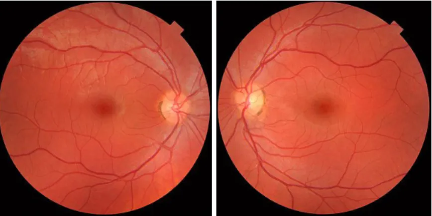
Figure 1.1: Fundus photographs of the normal both right (left image) and left eye (right image). Since the person is made to look into the camera, macula is in the center of the image in both the picture, and the optic disk is located towards the nose. [3].
Following are some modalities/techniques which comes under the broad category of fundus imaging[1]:
1. fundus photography (including so-called red-free photography) - image intensities represent the amount of reflected light of a specific waveband;
2. color fundus photography - image intensities represent the amount of reflected R, G, and B wavebands, as determined by the spectral sensitivity of the sensor;
3. stereo fundus photography - image intensities represent the amount of reflected light from two or more different view angles for depth resolution;
4. hyperspectral imaging - image intensities represent the amount of reflected light of multiple specific wavelength bands;
5. scanning laser ophthalmoscopy (SLO) - image intensities represent the amount of reflected single wavelength laser light obtained in a time sequence;
light optically corrected by modeling the aberrations in its wavefront;
7. fluorescein angiography and indocyanine angiography - image intensities rep-resent the amounts of emitted photons from the fluorescein or indocyanine green fluorophore that was injected into the subjects circulation.
Since the retina is not illuminated internally like that of in conventional photog-raphy where objects are illuminate naturally or using different illumination path if illuminated manually, external illumination projected into the eye as well as the light reflected by the retina must traverse the pupillary plane. Thus the size of the pupil, the small opening in the iris usually between 2 and 8 mm in diameter, has always been the primary technical challenge in fundus imaging. Fundus imaging is complicated by the fact that the illumination and imaging beams cannot overlap because that results in corneal and lenticular reflections diminishing or eliminating image contrast. Consequently, separate paths are used in the pupillary plane, resulting in optical apertures on the order of only a few millimeters. Because the resulting imaging setup is technically challenging, fundus imaging historically involved relatively expensive equipment and highly trained ophthalmic photographers.
1.3
Motivation for Fundus Photography
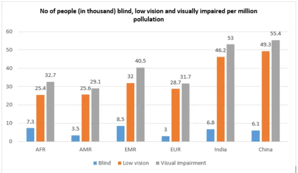
According to World Health Organization statistics, The number of visually impaired people across all ages on the earth was estimated to 285 million including 39 million blind crowd, In 2010[6]. It is projected by same organization that number of blind people might raise to 76 million by 2020 over a projected global population of 7.9 billion[7].
Globally the principal causes of visual impairment are uncorrected refracve errors and cataracts, 43% and 33 % respecvely. Other causes are glaucoma, 2%, age related macular degeneraon (AMD), diabec renopathy, trachoma and corneal opacies, all about 1%. A large proporon of causes, 18%, are undetermined, (Figure 2A). The causes of blindness are cataract, 51%, glaucoma, 8%, AMD, 5%, childhood blindness and corneal opacies, 4%, uncorrected refracve errors and trachoma, 3%, and diabec renopathy 1%, the undetermined causes are 21%.
From the Figure 1.2, it is significant that there is still huge need of advancement in ophthalmic sciences and technologies to overcome or prevent visual impairment problems. Hopefully, the new advances in fundus imaging will decrease few visual morbidity which are preventable with few prior precautions or post diagnosis by means of early sign of eye conditions. Except the age related macular degeneration, all other causes of blindness are avoidable if treated at right time. All of the mentioned
Figure 1.2: Global Visual impairment statistics in 2010.
causes except cataract needs fundus inspection. Through fundus check up all these signs can be detected and even treated at very initial stage and save person from permenanat blindness.
1.4
Historical Background
The concept of fundus photography was first introduced in the mid-1800s. The first attempt to image the retina in a cat was completed by the French physician Jean Mery, who showed that if a live cat is immersed in water, its retinal vessels are visible from the outside. The impracticality of such an approach for humans lead to the invention of the principles of the ophthalmoscope in 1823 by Czech scientist Jan Evangelista Purkyn (frequently spelled Purkinje) and its reinvention in 1845 by Charles Babbage. Finally, the ophthalmoscope was reinvented again and reported by von Helmholtz in 1851 and James Clerk Maxwell presented a colour photography method in 1861.
1st photographs of the retina were published by Jackman and webster in 1886[5]. But 1st commercial fundus camera was produced by Carl Zeiss in 1926, which was major breakthrough in fundus imaging. In next adaption, field of view (FoV) was significantly improved. As stated by Danaldson in[8] Metzger used method of side-to-side shifting to capture stereoscopic fundus photographs in 1927. After the invention of the electronic flash tube, researcher were able to direct light through the pupil. In
1953, Hansell and Beeson became pioneer to to successfully attach it to the fundus camera. A big leap in FOV took place first time 1960. The Pomerantzeff Equator-Plus fundus camera was big evolution in term of field of view. It had ability to capture or image up to 1480 area of retina. Also, as reported by Behrendt and Wilson in
1965, Carl zeiss’s nerve fiber layr photography technique using the traditional camera along with mentioned one was a new trend. According to Dobbins report, Steven Sasson invented the first digital camera at Eastman Kodak in 1975. From here on wards there was shift from analog to digital which helped in revolutionizing medical imaging and record keeping. In recent years, confocal scanning laser ophthalmoscopy has emerged as a solution to minim aberrations through poor dilation and to produce high-contrast, detailed images. Through the years, camera systems have evolved to boast sharper images, nonmydriatic wide-field options, pupil tracking, and, most recently, portability. Popular manufacturers in the market today are Topcon, Zeiss, Canon, Nidek, Kowa, CSO, and CenterVue.
Recently there have been signigicant technological advances in fundus imaging techniques that has radicalized retinal photography and increased ease of access as well as availability. In the process of making ophthalmic screening in remote areas a realizable possibility, the advances and improvements in telecommunication and smartphones plays important role(fig. 1.3). Advancement in these technologies made it possible to use Integrated adaptor-detector-based and smart phone based fundus cameras in remote areas also. both these falls under hand-held camera categories.
1.5
Technical Aspects
The latest technologies can help ophthalmologists improve diagnostic abilities and the treatment of eye disease. A fundus camera is such device that improves the ability of practitioners to view the retina in detail and store results for comparison. A fundus camera is a specialized low power microscope with an attached camera. Its optical design is based on the indirect ophthalmoscope. Fundus cameras are described by the angle of view - the optical angle of acceptance of the lens. An angle of 30, considered the normal angle of view, creates a film image 2.5 times larger than life. Wide angle fundus cameras capture images between 45 and 140 and provide proportionately less retinal magnification. A narrow angle fundus camera has an angle of view of 20 or less. A typical fundus optics system consists of a sequence of optic components such as objective lenses, condensing lenses, beam splitters, mirrors, diffusers, polarizers, masks which altogether direct the light illuminated from illumination system to the retina through the pupil of the eye, and also collects the light reflcted back from
Figure 1.3: Flowchart depicting evolution and scope of retinal screening and fundus photography [11].
retinal surface and direct it through imaging optics towards the sensor to form an image on detector screen. An illustration of a optics system given in an US patent filed and aproved in 2003 by Naohisa Shibata, Gamagori and Miwako Torii, Toyohasi is given in next section.
1.5.1 Fundus camera optics
Traditional photography works on principle that imaging ray and illumination rays uses different space (for both natural and artificial illumination) i.e. does not share common path. Fundus photography is a challenge to this this principle where we are forced to share common system aperture stop (pupil) and space for ray tracing. So we are forced to illuminate and image retina simultaneously.
The design of the traditional fundus camera system is based on monocular in-direct ophthalmoscopy. Reference layout for a traditional table-top fundus camera adopts common design by Knoll and others. But The basic optical design modern fundus camera is an adaptation of a reflex free indirect ophthalmoscope designed in the early 1900s to large extent. The major principle involved in reflex free indirect opthalmoscopy states that in order to avoid back reflections from the eye, imaging ray path (i.e. rays reflected form retina) and the ray path observed by illumination rays should use different space of the eye[17]. Complex optical system for retinal
imaging i.e. fundus camera is nothing but a further advancement in this principle with a little challenge. The major challenge in retinal or fundus imaging is that the retina of the eye must be illuminated and imaged simultaneously. So unique set of designs for fundus cameras are developed after consideration of this unique challenge. Most common solution is to to design two separate system in which one system is used for illumination and another system is used for imaging, and both system shares common optics. A schematic diagram from followed by analysis of such a device from the patent literature is provided in Figure 1.4[12]. Basic optical layout of this design is similar to the system provided by Knoll in 1969 and other patents dated from 2002 2006. Hence this particular design was chosen for analysis in [9]. Though the basic design exists since 40 years, there has been very little changes in it. It shows the effectiveness of this particular design.
Figure 1.4 shows block diagram of almost similar system. Analysis given below shows insight into the design principles involved in this device. As mentioned earlier, common idea is to to design two separate system in which one system is used for illumination and another system is used for imaging. Lenses on way of closely dotted lines in Figure 1.4 forms imaging system. Mirror with a central hole(donut shaped mirror), also plays part in same. Objective lens forms an intermediate image of the retina and imaging lenses trace this intermediate image to the camera or sensor system for snapshot imaging. The fundus camera compensate for the defocus present in the patient’s eye with the help of Translation of lens. The mirror with the central hole is nothing but kind of conjugate aperture to the pupil. The eye or retina is imaged through the pupil. The size of pupil it controlled by the size of the central hole of mirror i.e. it effectively limits the entrance pupil diameter of optical system and hence the imaging pupil diameter. Anather imaging path from dichroic mirror is used for continuous observation of the retina [9]. they uses infrared imaging camera for the same. Dichroic mirror bifurcates and optical path for above infrared light. The IF light reflected from fundus is reflected by dichroic mirror, passes through relay lens and then reflected by mirror towards CCD camera for observation having a sensitivity to the infrared region so that image of fundus is formed at photographic surface of camera.
The illumination system is comparatively more complex. The illumination and imaging systems share the objective and the eye. In such cases, backreflections from the such common optics can be a considerable problem. Despite using excellent an-tireflective (AR) coatings, backreflections from the common optics sometimes can be even greater than the light reflected by the retina . To avoid or overcome backreflec-tions, Some corrective measures must be implemented in the design of an illumination
system [17].
This particular camera has two light sources. Halogen lamp and visible light source. Halogen lamp is used for continuous observation. Light emitted by halogen lamp is converted into infrared light by an infrared filter. This IF light then passes through condenser lens and is reflected by a half mirror to annular aperture in illumination lenses. Light from visible light source is used for photographing. Visible light passes through another condenser lens placed between half mirror and source, and then transmitted by half mirror (i. e. both illumination path uses the same principles). The sources are conjugate to an annular aperture. This light reflected by mirror, transmitted though a black-dot plate and relay lens to form an intermediate image in vicinity of an aperture of an donut shaped mirror. This mirror is alligned coaxially with the optical axis of the imaging system. This light is then passed through objec-tive lens to and through pupil illuminate retina. The central hole of donut shaped mirror controls the size of the unilluminated portion of the pupil of eye.
As previously mentioned, One of the important goal in design of the fundus camera is eliminating backreflections. The careful placement of the annular aperture, the holed mirror and iris, 22 in the system eliminates the backreflections from the cornea to large extent. In the process of coupling of the imaging and illumination paths and managing system backreflections, holed mirror plays critical role. It allows to illuminate the outer edges of the pupil, and hence illuminating the retina with center part of pupil unilluminated. This unilluminated part is used for the purpose of imaging the retina while simultaneously minimizing corneal backreflections. The stray light that could pass through the hole in center of the mirror and can cause difficulty in resolving image is blocked by the annular aperture. Remaining cornea backreflections at the edge of the image is then taken care by iris. Black dot 19 is placed conjugate to the front surface of objective, which then helps in eliminating backreflection from objective Because the light that would be backreflected from the front surface of the objective is absorbed by the black dot.
The design objectives of the illumination system are to eliminate backreflections from the cornea and maximize the irradiance on the retina and the camera while maintaining complete illumination across the portion of the retina being imaged. Completing a successful design requires understanding the trade-offs that come with the three criteria listed. These trade-offs include: resolution, detector irradiance, effi-ciency, and uniformity. Existing literature only gives schematics that do not include enough information to recreate a working system. This leaves the engineer to deter-mine which parameters are optimal for the task of retinal imaging and illumination and how changing these parameters affects the performance of the system.
Figure 1.4: block diagram schematic of a fundus camera from a patent filed in 2003 [12]. The annular illumination pattern is created at the iris by the center of the illumination path using an annulus, and a mirror with a central hole located at the conjugate planes of the iris. Back reflections from the objective are removed by black dot plate.
1.5.2 Commercially available fundus cameras
Table 1.1 states names and different technical specifications of modern days table top, hand held and smart phone based fundus cameras along with few additional features[11]. From table, it is evident that field of view for all the cameras is very limited. Major cause is all the cameras uses lens optics and the collimated rays has to pass through opening of the pupil which acts as system aperture stop. As result, the rays near edges of cornea get filtered at the pupil, Hence peripheral areas remains undetected.
Table 1.1: Technical specification of different fundus cameras available
Name Design principle FOV Image sensor Additional features Miniature table-top design
3nethra Reflective imaging
using white light 450
3MP, computer in-terface
Corneal imaging color, red-free images
dRS (Digital Retinogra-phy System)
Reflective imaging using white light
450 H 400 V 5MP, with 10.4MP touchscreen col-ordisplay;WiFi and LAN connection
Multi field acquisition, color, red-free, stereo pair images
Topcon TRC-NW8Fplus
Reflective imaging
using white light 450
8MP digital SRL camera
Stereo photography, color, red-free images, fluores-cein angiography
iCam Reflective imaging
using white light 450
12-bit CCD, 5.2MP, computer interface
multiple image views, im-age sharpening,color, post processing for red free im-ages
EasyScan Confocal SLO, with green, NIR 600 H 450 V Photodetector-based computer interface
Enhanced view of pe-riphery, better resolution, automated iris detection, pseudo-color
Zeiss VISU-CAM 200
Reflective imaging using white light
450
and
300
CCD 5.0 MP, 19 inch TFT
Color, red-free images, blue and red autoflores-cence, anterior segment imaging, stero image mode
Kowa Non-myd7
Reflective imaging
using white light 450
12 MP digital cam-era
Optic nerve head color, red-free images, pseudo-3D display
Canon CR-2 Reflective imaging
using white light 450
18 MP EOS digital camera
Cobalt- and red-free imag-ing California ultra-widefield retinal imag-ing Reflective imaging using multiple wavelengths 2000
Not specified Composite color, red-free, autofluorescence, fluores-cein angiography, indo-cyanine green angiogra-phy
Oculus Im-ageCam2 digital slit lamp camera
Slit lamp based Not specified 2 MP resolution Viewer Software for an-terior segment, fundus, sclera, etc.., with USB in-terface
Table 1.2: Technical specification of different fundus cameras available
Name Design principle FOV Image sensor Additional features
Point-and-shoot off-the-shelf digital camera-based Conventional optics + camera lens 500 Camera CMOS sensor
-Integrated adaptor-detector-based (hand-held)
Volk Pictor Reflective imaging
using white light 400
5 MP, TFT LCD detector , WiFi/USB connec-tivity
Color, corneal imaging
iExaminer + PanOptic ophthalmo-scope iPhone+PanOptic ophthalmoscope 250
iPhone 4S camera Color, corneal imaging, cobalt blue filter
VersaCam Reflective imaging
using white light 400
2 MP camera, 3.5-inch color LCD Color imaging Kowa Genesis-D
Conventional optics Not Speci-fied 2 MP digital cam-era, 2.5-inch TFT LCD display JedMed HO-rus Scope
Reflective imaging Not specified 2 MP HD cam-era, 3.5 inch color LCD, PC connec-tivity through USB
Color Imaging, general ex-aminations for ear, nose, and throat and women’s health Optomed Smartscope Conventional optics 400 5 MP CMOS im-age sensor, 2.4-inch TFT LCD detec-tor, PC connectiv-ity through USB
Anterior eye module, oto-scope, dermatoscope Riester ri-screen multifunc-tional digital camera system
Slit lamp base
600 H 450 V 3.5 inch full HD full color TFT-LCD display
Smarphone based (hand-held)
Harvard Medical School Pro-totype
external lens Not specified iPhone
-Ocular Cellscope
iPhone +
conven-tiaonal optics 550
iphone
-PEEK iPhone + external lens
-1.6
Limitations
The traditional fundus cameras faces number of limitations. First, they form a bulky system, incorporating a host of optical and mechanical components, and the alignment of every part with respect to another is a critical parameter. Second, the operation of such a sophisticated system requires skilled personnel. Third, the bulkiness and com-plexity restrict its use only in clinical/lab settings, difficult to be accessible in remote area. Fourth, the number of optical components and add-on features in more recent devices renders the cost of the cameras exorbitantly high for them to be installed in rural locales where much of the population is subjected to ailments amounting to visual morbidity.
From Table 1.1, it is evident that almost all fundus cameras have limited FOV. This limits us to imaging only central part of retina. Early signs of disease can be present in the periphery of your retina and remain undetected when using traditional methods. The complications in designing an lens optical system and cost of manufacturing is also too high. Also, all present systems use lens imagery which usually suffers from few major optical aberrations which causes an imperfection in image formation by an optical system.
Some of major aberrations are
Chromatic aberration, caused by differences in refractive index for different wave-lengths of light, in contrast with monochromatic aberration, which occurs for all frequencies of light. So it occurs when a lens is either unable to bring all wavelengths of color to the same focal plane, and/or when wavelengths of color are focused at different positions in the focal plane. Since red color has longest wavelength, it is focused to furthest point of optical axis or has longest focal length.
Spherical aberration, as shown in Fig. 1.5, occurs when light rays pass through a lens near the edge i.e. occurs due to the increased refraction of light rays when they strike a lens near its edge, in comparison with those that strike nearer the centre. The rays that hits lens away from the optical axis (near to edge) get focused close to lens on optical axis(positive spherical aberration).
Coma or Comatic aberration is inherent to certain optical designs or due to im-perfection in the lens or other components that results in off-axis point sources such as stars appearing distorted, appearing to have a tail (coma) like a comet. Fig. 1.6 shows comation where collimated of axis rays are passed through a lens. A reverse tail like comet is formed in spot diagram showing negative coma aberration.
Defocus aberration occurs when a system is out of focus. Aberration of light, which produces an apparent motion of celestial objects. Relativistic aberration, the
Figure 1.5: Spherical aberration in a lens. When parallel rays are passed through lens, ideally all rays should focus at the one point called focal point. But as it can be seen in zoomed box, due to presence of the spherical aberration, the rays that are farther from optical axis intersect the optical axis closer to the lens compared to that of those with are near to optical axis.
Figure 1.6: Coma of a single lens which shows off-axis collimated rays which ideally were supposed to focus at one point hits at different point on focal plane and forms a tail like structure as it can be seen in spot diagram.
distortion of light at high velocities.
1.7
Proposed Approach to Overcome Limitations
In this thesis, we suggest an alternative optics for fundus imaging. As shown in next chapter, Design constrains of aplanat helps to remove all major aberrations observed by lens without adding any extra corrective measures as like those of lens optical systems. And since the proposed system does not have complex set of lenses, compli-cations of the system are and helps in reduction of cost significantly. Major advantage of the system is it offers wide numerical aperture large field of view and system size remains to that of hand held device. Large NA and high radiation efficiency abolish the need of pupil dilation making process painless for patient.
Chapter 2
Fundus Imaging using Aplanat
Early signs of disease can also be present in the periphery of the retina and remain undetected for a long time when using traditional methods because of limited field of view. The bulkiness and requirement of skilled operand restricts such system from being available in remote areas. Being prone to some unavoidable aberrations, image quality by such system is always compromised. Proposed system successfully addresses most of these issues.
2.1
Proposed System
We propose a system that uses an aberration free reflector called Aplanat instead of the conventional lens system for the fundus imaging. So Imaging optics will be based on reflection unlike the convectional system which uses lens system and hence refraction based system. Which results in very negligible aberrations. Also, small reflector size makes it a handheld system with minimum complexity and power loss for illumination purpose. Working under thermodynamic limit and high numerical aperture makes it possible to inject maximum light at wide angle inside eye which abolish the necessity of mydriasis. The excitation of the radial fibres of the iris which increases the pupillary aperture is referred to as a mydriasis. More generally, mydri-asis also refers to the natural dilation of pupils, for instance in low light conditions or under sympathetic stimulation. Negligible power loss in ray path makes it possible to work with very low irradiance and results in a patient friendly fundus imaging sys-tem. The illumination rays and imaging rays follows exactly same ray path. Hence backreflection can be a problem. But it can be avoided with using exposure for very short time right before capturing the image.
Figure 2.1: Proposed system. Two way arrow indicates that same path will be used for both illumination and imaging and hence ray travel in both the direction.
2.2
Aplanat
Aplanat is a term referred to a reflecting or refracting surface which is free from spherical, coma and chromatic aberrations. So Aplanatic system a system in which both spherical aberration and coma were rigorously corrected near to an optical axis. The basic design of aplanat resembles to Cassegrain reflectors (Fig. 2.2). Karl Schwarzschild in 1905 laid the foundation of deriving aplanatic solutions for two-mirror telescope. Schwarzschild managed to derive closed analytical formulas that described the shape of the mirror surfaces in such a telescope [13]. These designs were for far-field imaging (i.e.) for object at infinity. Subsequently, Chretien (1922) and Maksutov (1932) concretized these expansions for Cassegrain and Gregorian sys-tems, respectively, which gave rise to the telescopes aplanatic in the third order of the aberration theory. A. K. Head adopted these aplanatic equations for near field (close object) problem in 1960 [14].
Aplanat is further classified as: 1)Folded Aplanat
2)Unfolded Aplanat
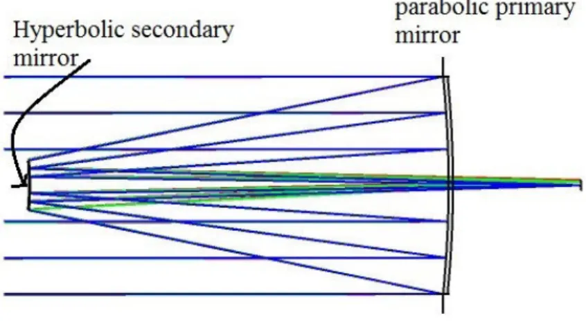
This classification is roughly based on the path of ray emitted from source and gathered at the focus. As we can see in figure 2.3, ray is reversed twice while trav-elling from source to focus, hence referred as folded aplanat. Whereas, in the design showed figure 2.4, caustic from the primary mirrors forms in front of the focal plane of secondary mirror i.e. rays is continuously travelling forward, hence referred as unfolded aplanat. As one can observe from fig. 2.2 and fig 2.3, the basic design of aplanat resembles to Cassegrain reflectors. The major difference lies in mirror type. Cassegrain reflector telescopes uses parabolic conic structure as primary mirror and hyperbolic secondary mirror whereas aplanat design mainly uses elliptical conic as
Figure 2.2: Schematic of a Cassegrain reflector.
primary mirror and hyperbolic as secondary mirror. In some special cases, Both the mirrors can be parabolic or one sphere and other plane in some special cases. But the functioning mechanism remains unchanged in both the cases. The ray coming from the object first strikes on primary mirror(objective) and is directed to the secondary mirror through total internal reflection. Then secondary mirror follows same and direct the rays to focal point where image is to be observed.
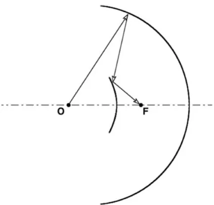
For high exit numerical aperture (NA) in an folded aplanat, the focus needs to be inside the optical system which might be problematic to keep imagery system. Hence for the imaging purpose, [16] proposes to use unfolded aplanat shown in Figure 2.4 where both object point and image point are out of the reflector structure which gives ease of prototyping and practical installation.
In Figure 2.4, path OPQF shows a typical ray from object point O to focus or image point F. The first or primary mirror is specified by polar coordinates (ρ, θ) about object point O and the secondary mirrors is specified by polar coordinates (r,φ) about image point F.
Variable parameters(varies for each ray) for a particular aplanat design:
θ - angle made by ray emitting from object point O with respect to optical axis.
ρ - polar distance of ray from object to primary mirror.
l - distance travelled by rays after reflected by primary mirror to secondary mirror.
r - polar distance of a ray from secondary mirror to object point.
φ- angle made by ray reflected from secondary mirror and gathered at image point.
ρo,ro and lo are fixed parameters for a particular design. They represents distance between mirrors as shown in 2.3
Figure 2.3: Cross section of a near-field two-mirror folded aplanat. Light starting from O is re-versed(folded) twice before reaching to focus, Hence the name.
Figure 2.4: Cross section of a near-field two-mirror unfolded aplanat. Light ray starting from O at arbitrary angle θ under constrain N Ain = sin(θmax) is traced at angle φ with constrain
N Aout = sin(φmax) at focus F. The dotted curves represent imaginary continuations by equations
Chapter 3
Equations for Aplanat
The figure 3.1 shows cross section of an unfolded aplanat and the path OPQF is a ray path of a typical ray from object O to image F. The primary mirror is specified by polar coordinates ρ, θ about object point O and the secondary mirror is specified by polar coordinatesr, φ around image point F. The angle of incidence and reflection of the ray at the primary mirror isi and the distance PQ isl. The total distance between the object point and image point of aplanat is ρo+ro−lo. The derivation for both
the contour is derived by tracing rays from a point source at object O to the focus F and simultaneously putting following constraints to eliminate major aberrations.
3.1
Fundamental Principles
1. Aplanats satisfy Fermat’s principle of constant optical path length. This constrain helps in elimination of the spherical aberration as travel time of each ray is same (not necessarily distance if the medium through which ray travels changes. But here as medium is same throughout the path, even distance is similar).
ρ+l+r=const.=ρo+lo+ro (3.1)
2. Abbe’s sine condition of constant magnification m .
m= sin(θ sin(φ)) =const= N Ain N Aout (3.2) OR m=− sin(θ sin(φ)) = const.=− N Ain N Aout (3.3)
Figure 3.1: Ray path for aplanat
Equation 3.2 is magnification condition for folded aplanat [14, 15] whereas equation 3.3 is magnification condition for unfolded aplanat [16]. The negative sign in equation 3.3 is just to pertain the unfolded converging design. Converging meaning in unfolded design, caustic from the primary mirrors forms in front of the focal plane of secondary mirror rather than that of like behind in folded aplanat design.
3. Snell’s law at ray-mirror intersection (i.e at point P and Q). 1
ρ(θ)
dρ
dθ =−tan(i) (3.4)
ρ(θ) is just to give inference that length of ρ is dependent on
Input dimensional parameter are ρo,lo and ro. Only two of these three lengths are needed as third one establishes the dimensional scale.
Projection of PQ perpendicular to axis
lsin(2i+θ) = ρsin(θ)−rsin(φ) (3.5)
Projection of PQ parallel to axis
lcos(2i+θ) = ρcos(θ) +rcos(φ)−(ρo+ro−lo) (3.6)
3.2
Derivation
We will eliminate variables r, l and φ from equation 3.1, 3.3, 3.5 and 3.6 and get a expression for tan(i) to substitute in equation 3.4. This gives a differential equation connecting ρ and θ.
Multiplying 3.5 by cos(φ) and 3.6 by sin(φ) and adding them gives
lsin(2i+θ+φ) = ρsin(θ+φ)−(ρo+ro−lo) sin(φ) (3.7)
and multiplying 3.5 by cos(φ) and 3.6 by cos(φ) and subtracting them gives
lcos(2i+θ+φ) = ρ(θ) cos(θ+φ) +r−(ρo+ro−lo) cos(φ) (3.8) Substituting value of r in above equation from 3.1 and simplifying, we get
l+lcos(2i+θ+φ) = ρ(θ) cos(θ+φ)−(ρo+ro−lo) cos(φ)−ρ(θ) + (ρo+ro+lo) (3.9) division of 3.7 by 3.9 gives
sin(2i+θ+φ) 1 + cos(2i+θ+φ) =
ρ(θ) sin(θ+φ)−(ρo+ro−lo) sin(φ)
ρ(θ) cos(θ+φ)−(ρo+ro−lo) cos(φ)−ρ(θ) + (ρo+ro+lo) (3.10) Now sin(2i+θ+φ) 1 + cos(2i+θ+φ) = tan(i+ 1 2(θ+φ)) = tan(i) + tan(12(θ+φ)) 1−tan(i) tan(12(θ+φ)) (3.11) writing tan(1 2(θ+φ)) = sin(θ+φ)
1 + cos(θ+φ) in equations 3.10 and 3.11 and expanding all trigonometrical functions of θ and φ, we get the value of tan(i).
tan(i) = ρ(θ)( 1−cos(θ) sin(θ) + ( 1−cos(φ) sin(φ) ))−l0( 1−cos(θ) sin(θ) )−(ρ0+r0)( 1−cos(φ) sin(φ)
l0 −(ρ0+r0)(1−cos(sin(θ)θ))(1−cos(sin(φ)φ))
(3.12)
sin(φ) = −sin(θ) m and so cos(φ) = ± r 1−sin 2(θ) m2 (3.13) and 1−cos(φ) sin(φ) = m∓p(m2−sin2(θ)) sin(θ) (3.14)
To resolve the ambiguity of sign in above equations, following conventions will be adopted. In 3.13, the positive sign will be taken so that as θ→0,φ →0. This would lead us to
1−cos(φ) sin(φ) =
m−p(m2−sin2(θ))
sin(θ) (3.15)
Since m has been taken inside the square root so the convention needs some con-straints to pertain sign, 3.15 is correct if p(m2−sin2(θ)) is given the sign of m, i.
e. q (m2−sin2(θ) = mk r 1−sin 2(θ) m2 k
So assumed convention should be used under above constrain. Substituting 3.15 in 3.12, writing (ρ0+l0r0) =k and using 3.4, we get
1 ρ(θ) dρ(θ) dθ = (lρ0) sin(θ){1−cos(θ) +m− q (m2−sin2 (θ)} −sin(θ){1−cos(θ) +km−k q (m2−sin2 (θ)} k(1−cos(θ)){m−q(m2−sin2 (θ)} −sin2 (θ) (3.16)
Multiply both the side of 3.16 by l0
ρ, we get d dθ l0 ρ(θ) = l0 ρ(θ)F(θ) +G(θ) (3.17) Where F(θ) = sin(θ){1−cos(θ) +km−k p (m2−sin2(θ)}
sin2(θ)−k(1−cos(θ){m−p(m2−sin2(θ)}
G(θ) = sin(θ){1−cos(θ) +m−
p
(m2−sin2(θ)}
Equation 3.17 is a first order linear differential equations in l0
ρ. It’s complete
solution is sum of (a) any particular solution and (b) an arbitrary multiple of the solution of the corresponding homogeneous equations.
(a)Particular Solution is obtained by putting a trial solution of form A+Bcos(θ) in 3.17. After simplification, we get the particular solution as
l0 ρ(θ) = 1 +k 2k + 1−k 2k cos(θ) (3.18)
(b)Homogeneous equations for 3.17 is
d dθ l0 ρ(θ) = l0 ρ(θ)F(θ) (3.19) Whose solution is l0 ρ(θ) =Cexp Z F(θ)dθ
Above integral can be evaluated by the substitution
γ(θ) = cos(θ) + q (m2−sin2(θ) (3.20) i.e. cos(θ) = γ 2(θ)−m2+ 1 2γ(θ) which gives l0 ρ(θ) = C[γ(θ)−1 +m]α[γ(θ) + 1−m]β[γ(θ)(k+ 1) + (1−k)(1 +m)]2−α−β γ (3.21) For the ease of representation, above equation uses following substitutions.
α= mk
mk −1, β =
m m−k
The value arbitrary constant C is determined by putting ρ = ρ0 in 3.21 when
θ = 0, That gives us
C = l0(1 +m) 4ρ0mα(1 +m)2−α−β
And as mentioned earlier, the general solution is the sum of 3.18 and 3.21.
Hence, the final solution gives us the contour equation for the primary mirror ρ(θ) as
lo ρ(θ) = 1 +k 2k + 1−k 2k cosθ+ (ro)(1 +m)[γ(θ)−1 +m]α[γ(θ) + 1−m]β[γ(θ)(k+ 1) + (1−k)(1 +m)]2−α−β 4kρoγ(θ)mα(1 +m)2−α−β (3.22)
Using reversibility of the system, we find out that secondary mirror r(φ) will have similar equation with m replace by m1.
Let’s consider M = m1, then
lo r(φ) = 1 +k 2k + 1−k 2k cosφ+ (ρo)(1 +M)[δ(φ)−1 +M]α ′ [δ(φ) + 1−M]β′ [δ(φ)(k+ 1) + (1−k)(1 +M)]2−α′ −β′ 4kroδ(φ)Mα′(1 +M)2−α′−β′ (3.23) where α′ = M k M k−1, β ′ = M M −k, δ(φ) = cos(φ)− q M2−sin2(φ)
Where m is the constant magnification given in equation 3.2 and 3.3, and they introduced a dimensionless parameter for shorthand notation to simplify system di-mensional parameters of Eq. 3.1 and Fig. 2.4 and refered it ask. Also, Equation 3.22 and 3.23 each describes one side of the optic axis of the reflector contours (primary mirror of above the optical axis and secondary mirror below the optical axis). The remaining side is simply the mirror image of of given contour. Complete hollow tube like structre of aplanat can be found by revolving the above curves around optical axis.
3.3
Special Cases
a) if m = 1 then ρo ρ(θ) = ρo−ro+lo 2lo + ro−ρo+lo 2lo cosθ (3.24) and ro r(φ) = ro−ρo+lo 2lo + ρo−ro+lo 2lo cosφ (3.25)These are polar equations of conics about focus. In general one mirror is elliptical and the other is parabolic. but in special cases, both the mirrors can be parabolic or one sphere and other plane.
b) if m= -1 then ρo ρ(θ) = ρo+ro+lo 2lo − ρo+ro−lo 2lo cosθ (3.26) and ro r(φ) = ro+ρo+lo 2lo − ρo+ro−lo 2lo cosφ (3.27)
These are also polar equations of the conics about a focus, but in this case both the mirrors are geometrically similar (double ellipsoid). Thus for a system with unit magnification, the mirrors must be conics. The ease and cost of fabrication would be minimized when two mirrors are identical.
3.4
Performance
Rays that cross the waist without intersecting the primary mirror are considered as loss and not used for imaging. A trade off arises as when the throat size is small, the FOV or the angle that aplanat can cover is bigger, but if throat is too wide, the power loss or direct scattering though throat is also higher. But aplanat offers too high numerical aperture for a handy design. It is free from basic 3rdorder aberrations
such as spherical, chromatic and coma. Aplanat has unique ability to focus divergent rays making it capable of collecting all rays from a lambertian sources. Hence all the light that leaves source, except minute losses through throat, all of it get focused. High radiation efficiency makes it possible to work with even low intensity light for good illumination of object.
Chapter 4
System Analysis
Aplanat discussed along with parameters in last chapter was used for the simulation purpose. Process follows as coordinates in MATLAB exported to Solid Edge where aplanat reflector in CAD object form was made then imported in Zemax.
4.1
Methods
An standard eye model along with the aplanat reflector was modelled in Zemax Optical Studio 15.5 with a sensor at the end in coincidence with the focus point of the aplanat. Zemax Optical Studio tool does not offer provision of modelling a complex and random geometry through the lens data editor or non-sequential editor. But Zemax has powerful and flexible CAD import capabilities, and supports common CAD exchange formats. The ability to import CAD objects into Zemax is very important, particularly when undertaking complex geometrical reflective structures with intricate set of equations. Zemax supports four CAD formats: STL, IGES, STEP and SAT. Of these, only STL uses facets to represent the object: the other three model the object as a smooth, continuous surface shape. Also, There are two distinct ray tracing modes of ray tracing supported by Zemax Optical Studio viz. Sequential and Non-Sequential ray tracing. In sequential ray tracing, Rays are traced through a pre-defined sequence of surfaces while travelling from the object surface to the image surface. Rays hit each surface once in the order (sequence) in which the surfaces are defined. Such systems are fast in term of computation and well suitable for imaging systems. Major pitfall from which sequential ray tracing suffers is that it is very hard to account for total internal reflections. Non-sequential ray tracing implies that there is no predefined sequence of surfaces which rays that are being traced must hit. The objects that the rays hit are determined solely by the physical positions and properties of the objects as well as the directions of the rays. Rays
may hit any part of any non-sequential object, and may hit the same object multiple times, or not at all. This can be contrasted with sequential ray tracing where all of the rays traced must propagate through the same set of surfaces in the same order. In sequential mode in Optical Studio, all ray propagation occurs through surfaces which are located using a local coordinate system. In non-sequential mode, optical components are modeled as true three-dimensional objects, either as surfaces or solid volumes. Each object is placed globally at an independent x, y, z coordinate with an independently defined orientation. But often times it is necessary to combine the two techniques. A design which uses both methods of ray tracing is often referred to as a mixed-mode system, a hybrid system, non-sequential ray tracing with ports, or mixed sequential/non-sequential mode. A collection of non-sequential objects are setup inside of a non-sequential group. This non-sequential group is part of a larger sequential system. Sequentially traced rays enter the non-sequential group through an entrance port, and exit the group through an exit port to continue propagating through the sequential system. This mode of simulation is ideal for systems that are inherently sequential, but contain one or more components more easily modeled as genuinely 3D objects. Since our needs demand to utilize image quality abilities of Zemax to verify imaging performance of the optical system and also uses a complex reflector surface (aplanat), We choose to design system in mixed sequential mode.
Figure 4.1: Box diagram of optical system modelled in Zemax .
4.2
Eye Model
Optical models of the eye are used to design instruments to look into the eye (for example to check the uniformity of illumination of a fundus camera), to design in-struments that the eye looks through (including some properties of ophthalmic lenses, contact lenses and intraocular lenses), and to investigate the optical system of the
eye itself (including the effects on retinal image formation of eye pathology such as corneal scarring and cataracts).
There have been literally dozens of eye models published over more than 150 years, from very simple reduced eyes consisting of a single refracting surface to very complex models with more than 4,000 refracting surfaces. Some models have a gradient index crystalline lens, some represent the gradient index with two or more homogeneous shells, and some have a homogeneous lens.
There is no ideal optical model of the eye that is best for every purpose, and a more complex model does not necessarily represent all eyes, or any particular eye, more accurately. For this simulation purpose we used a sequential model designed in zemax. Two sequential models are used commonly, One where fundus of the eye is imaged by an external optical system i.e. where retina is acting as object surface and another where eye is looking through some optical system so retina is image surface. Our optical system needed first type of model as our main goal is fundus imaging.
Figure 4.2: Zemax model of human eye where fundus is treated as a physical object for imaging purpose .
Figure 4.2 shows Zemax model of human eye where fundus is treated as a physical object. The model uses F, d, and C wavelengths weighted 0.1, 0.4 and 1 respectively to represent the spectral reflectance of the fundus, equally weighted field angles of 0,
Figure 4.3: Dimentionas used for the zemax model of human eye shown in Figure 4.2.
10 and 20 degrees and a 4mm diameter iris aperture. The image space is afocal [20]. Whereas Figure 4.3 shows dimensions of different layers of eye where they are treated as lenses with respective refractive indices. Iris was treated as system aperture stop for the complete optical system and system was tested for 2mm and 4mm diameter of pupil size. The distances between different layers and few other parameter values are taken from [21] and have generally been rounded off for simplicity when this has been found to not be significant.
The pure spherical ball model of the eye doesn’t offer complete accuracy. The light enters the eye through the cornea, which has 2 layers 0.52mm apart, and which lens radius is different but has pretty much similar refractive index of n = 1.376. Then light passes through the anterior chamber, which contains aqueous humor has relatively lower index of refraction of approximately n = 1.336(approx similar to water). The thickness of this aqueous front part is taken as 3.1mm. Aqueous humor ends at the iris plane and the eye lens. Iris has abilities to change the diameter which acts as aperture stop for the optics system and controls the numerical aperture as well as radiance entering the eye(i.e. it decides how much light to allow into the eye). The eye lens has unique ability to change the shape and it’s refractive power. Because of this, eye can accommodate to object at different distances. A circular muscles called ciallry muscles relaxes or tightens the zonules to enable the lens to change shape for focusing. The lens is built from several nested shells. In a first approximation, only one optical medium is assumed, while more refined models distinguish a crystalline
core lens and a surrounding lens capsule. Behind the lens, the light passes through the vitreous humor. Vitreous humor is again the transparent jelly-like tissue filling the eyeball behind the lens with refractive index of 1.337(again close to that of water). The shown in front of retina in figure 4.3 is all filled with vitreous humor. The ray passed past to vitreous humor is received at the retina where the detection of light takes place. The rays scatters from retina in all directions. The rays that follows same path used for illumination but in reverse way contributes for the imaging then.
4.3
Aplanat reflector modelling and import to Zemax
As mentioned in the section 4.1, Zemax doesn’t have abilities to directly model the aplanat through lens data editor or non sequential component editor. So we choose to import Aplanat reflector as non-sequential object in a sequential system designed in Zemax which has eye model and sensor as sequential components.
Figure 4.4: Box diagram showing steps involved in importing aplanat reflector in mixed sequential optical system in Zemax
4.3.1 Getting Cartesian data points
Equation 3.22 and 3.23 were first coded into MATLAB. from the given polar co-ordinates, we found the corresponding Cartesian coordinates using basic conversion equations and saved for each mirror. Initially Cartesian coordinates for primary mir-ror and Cartesian coordinates for secondary mirmir-ror were stored differently and then ending for primary mirror and beginning for secondary mirror was chosen manually with interpolating a middle point by intuition.
Figure 4.5: Box diagram of work in MATLAB.
4.3.2 Using Solid Edge
The 2-D Cartesian coordinates created in MATLAB were used to model aplanat in Solid Edge. Solid Edge ST8 version was used for the same. The X coordinate was given as Z coordinate while importing data points to Solid Edge and X coordinate column was filled with same number of zeros. Reason behind this was optical axis of Optical Studio Zemax is along Z-axis. So to align or to bring the aplanat axis in coincidence with complete complex optical system, the given changes were made. From the given data points, a 2-D curve was drawn in Solid Edge first which then was swept around the axis to form a hollow tube. And as final step, in order to export the reflector as CAD object so that it can be used as non sequential object in Zemax, a thickness was given to the surface from outer side. In order to maintain faceted smoothness or reflector, inner size was not chosen. CAD object can be exported in STL, STEP, IGES and SAT. But as mentioned earlier, Because of the inefficiency in the tool, we were forced to choose STL format even though we looses smoothness of optical surface in this.
4.4
Optical System Design
Figure 4.7 is a image of the lens data editor(LDE) of the optical system desging of fundus camera using aplanat and the 3D layout of designed system is shown in Fig.4.8. Normally for any system, LDE has 3 basic surfaces viz. OBJECT,STOP and IMAGE. First 6 surfaces belongs to eye model which covers retina as object and pupil as stop. 7th surface is connecting lens data editor to non-sequential object editor. Surface 8 defines exit location and dimension i.e. simulations follows where ray left 6th surface and where they hit on 8th surface treating aplanat as the black box. IMAGE surface defines where rays are to be collected finally.
Figure 4.7: Lens Data Editor of the system.
4.5
Results
4.5.1 Conjugate plane of Retina
Fig. 4.9 and 4.10 shows conjugate plane of retina formed using these two aplanats. De-sign parameters used for narrow field aplanat are ρo = 120, lo = 4, ro = 120, N Ain = 0.99, N Aout = 1 . This aplanat has abilities to illuminate more that 1200 of retina but
gives clustered conjugates of the peripheral points. But it gives distinct conjugate plane for for 60 to 400 area of retina in both the direction from optical axis i.e. it
gives almost 800 field of view leaving a 120 hole at the center.
We choose to make the throat wide which resulted into the detection of peripheral area of retina at cost of increased hole size at the center. Design parameters used for this wide field aplanat are ρo = 70, lo = 18, ro = 70, N Ain = 0.99, N Aout = 1 . This aplanat gives distinct conjugate plane for for 200 to 1000 area of retina in both the
direction from optical axis i.e. it gives almost 2000 field of view leaving a 400 hole at
the center.
Figure 4.9: Conjugate plane of retina using narrow field aplanat.
Hence, if common area is overlapped, combining FOV of these two designs makes us able to image image almost 2000 Field of view but still leaves a hole of 120 at the
Figure 4.10: Conjugate plane of retina using wide field aplanat.
4.5.2 Trade off
One of the disadvantages is rays that cross the throat without intersecting the pri-mary mirror are not focused. A trade-off arises because smaller the throat, smaller the hole size(untraced area at optical axis) but FOV reduces. Widening the throat (by increasing l0 leads to wide FOV, but leaves a significant untraced area at the
centre(hole) in align with optical axis. As we can see in the table 4.1, for the aplanat with very narrow throat, the detection point closest to optical axis is very near(60
symmetrical, but has very low total FOV. Throat widening results in large field of view at cost of increased undetected area at the center.
Sr. ρo lo ro N Ain N Aout hole size covered
area FOV 1 100 4 80 0.89 0.91 12 4-34 68 2 120 4 120 0.99 1 12 6-40 80 3 100 8 80 0.98 0.88 20 10-52 104 4 100 8 100 0.98 0.88 16 8-56 112 5 100 8 80 0.91 0.88 20 10-60 120 6 100 12 80 0.91 0.88 28 14-72 144 7 100 12 80 0.99 0.88 32 16-79 156 8 100 16 100 0.98 0.88 36 20-98 196 9 70 18 70 0.99 1 52 20-100 200
Table 4.1: FOV Comparison for different Aplanats (All the angles in last 3 columns are in0
4.5.3 Proposed solution
In order to image retina completely, 3 phases of imaging need to be done. Narrow field aplanat will be used to image the part near to optical axis of eye. Wide throat aplanat will be used to image peripheral region. Hole at center remained undetected through aplanat can be imaged using normal lens system. So final solution is to image:
• 60−400 using narrow field aplanat.
ρo = 120, lo = 4, ro = 120, N Ain= 0.99, N Aout = 1
• 260−1000 using narrow field aplanat(peripheral area).
ρo = 70, lo = 18, ro = 70, N Ain = 0.99, N Aout = 1
• Normal lens system for the center.
Exploiting the overlapping part in the images from all the system, stitching algorithm can be used later to form a complete image. This system leads to total FOV of 2000.
Due to
Conjugate point was found to be inside aplanat i.e. ahead of focus. Conjugate of retina is not plane, planer sensor couldnt detect Aligning sensor in perpendicular to incoming ray is not possible in zemax. Also, working with of axis sensor, can’t put multiple sensors.
4.5.4 Simulation results for normal lens system
Conjugate plane of retina being a curved surface and lying inside the aplanat which restricts us from using zemax tool for the imaging purpose as it can not have of-axis multiple center at desired location. For the imaging purpose, the sensors needs to be placed where maximum number of rays from a point on retina form a bundle after passing through both the reflective mirrors. Also, we loose smoothness and accuracy of reflector surface while importing the CAD object in STL form as other 3 datatypes which uses Non-uniform rational B-spline(NURB) connectivity to create mesh didn’t work. So 3D image reconstruction of retina was performed in tool developed by project partner.
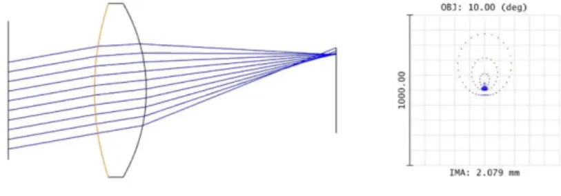
We made a lens system design in Zemax that will use same illumination system designed for Zemax and image central part of the retina. Fig. 4.11 shows 3D layout of lens system designed in Zemax. Note that aplanat here is not playing any role in
imaging. It is kept in design just to show that lenses are kept out of focus of aplanat hence even lens system can use same illumination system designed for aplanat. Fig. 4.12 shows FFT of point spread function of designed system. Image on right is 3D representation of PSF whereas image on left is graphical 2D representation of the same. Fig. 4.13 shows predicted output image of the normal lens system designed in Zemax. Output image is result of convolution of the input image with the point spread function of the system.
Figure 4.11: 3D layout of lens system designed in Zemax. Note that aplanat here is not playing any role in imaging. It is kept in design just to show that lenses are kept out of focus of aplanat hence even lens system can use same illumination system designed for aplanat.
Figure 4.12: graphical representation and actual PSF FFT result of the designed lens system in Zemax.
Figure 4.13: predicted output image of the normal lens system designed in Zemax. Output image is result of convolution of the input image with the point spread function of the system.
Chapter 5
Conclusion and Future work
This thesis proposes a totally different alternative optics for fundus imaging. This thesis covers literature survey of available fundus imaging including their add on features and limitations. And provides theoretical background for the new proposed aberration free optics called Aplanat.
5.1
Conclusion
Aplanat removes 3rd order aberrations significantly. the complexity involves only in reflector analysis which is solved already. Also, high numerical aperture with minimal design complexity and high radiation efficiency plays key role in making the imaging process Zemax tool can not be used to focus non-planer conjugate as it demands 3D plane for reconstruction. Hence the image Reconstruction analysis were performed on a tool developed by a colleague for illumination. Using tool, we were able to find conjugate plane of retina and map intensities back to retina surface in order to get 3D image plane.
A trade off involves in aplanat in terms of throat and field of View. Aplanat leaves a hole at the center symmetric around optical axis. Also, narrow throat aplanat of-fers limited field of view. Widening the throat gives large field of view cost of larger undetected area at the center. In order to overcome this trade off, two aplanats were used to cover wide field of view which still leaves a small hole at center. Hence we proposed 3 system solution to image wide area of retina without leaving any part undetected. Image the center by a normal lens system or conventional ophthalmo-scope or even mobile phone based cameras and use both the aplanat (wide field and narrow field) to reach peripheral area of aplanat. Normal lens system can image up to 300−400 whereas two aplanat together can cover upto 60−1000 in both the direction
stitching can be used to get the final complete image. A wide field of view of 2000
which accounts almost 87% of retina till Ora Serrata point. (Till Ora Serrata cover 230 degree of retina).
5.2
Future work
System offers complete image in three phases. So some stitching algorithm based on common area where order of image is known to be introduced in order to get final complete image. Present solution has conjugate plane of retina of a standard eye. Aplanat being a fixed device, change in eye lens of in eye will lead to shift conjugate plane to another location. So either sensors at new conjugate plane or post processing on captured image will be needed to counter the effect. Changing sensor for each patient can’t be practical solution. So post processing methods to overcome this problem must be introduced. If conjugate plane can be taken out of retina behind the illumination system point by introducing lens system, it will be easier for prototyping and variable power adjustment depending on patient.
References
[1] Abrmoff MD, Garvin MK, Sonka M. “Retinal Imaging and Image Analysis.” IEEE reviews in biomedical engineering. 2010;3:169-208. doi:10.1109/RBME.2010.2084567.
[2] California ultra-widefield retinal imaging. Available at
http://www.optomap.com/en-US/optomap-Retinal-Exam/ (last accessed June 12, 2018).
[3] https://en.wikipedia.org/wiki/Fundus photography [4] https://www.opsweb.org/page/fundusphotography?
[5] Jackman, W. T., and J. D. Webster. “On photographing the retina of the living human eye.” Philadelphia photographer 23.275 (1886): 275-276.
[6] World Health Organization. “Global data on visual impairments 2010.” Geneva: World Health Organization Organization (2012).
[7] http://www.who.int/blindness/Vision2020%20-report.pdf
[8] Donaldson, David D. “A new camera for stereoscopic fundus photography.” Trans-actions of the American Ophthalmological Society 62 (1964): 429.
[9] DeHoog, E., and J. Schwiegerling. “Optimal parameters for retinal illumination and imaging in fundus cameras.” Applied optics 47.36 (2008): 6769-6777.
[10] DeHoog Edward, and James Schwiegerling. “Fundus camera systems: a compar-ative analysis.” Applied optics 48.2 (2009): 221-228.
[11] Panwar, N., Huang, P., Lee, J., Keane, P. A., Chuan, T. S., Richhariya, A., , Teoh, S., Lim, T.H. and Agrawal, R. (2016). “Fundus photography in the 21st cen-turya review of recent technological advances and their implications for worldwide healthcare.” Telemedicine and e-Health, 22(3), 198-208.
[12] N. Shibata and M. Torii, “Fundus camera, U.S. patent 6,654,553 (25 November 2003)
[13] Terebizh, V. Yu. “Two-mirror Schwarzschild aplanats: Basic relations.” Astron-omy Letters 31.2 (2005): 129-139.
[14] Head, A. K. “The two-mirror aplanat.” Proceedings of the Physical Society Lon-don. Section B 70.10, 945-949(1957).
[15] Nakar, Doron, Daniel Feuermann, and Jeffrey M. Gordon. “Aplanatic near-field optics for efficient light transfer.” Optical Engineering 45.3 (2006): 030502. [16] Feuermann, Daniel, and Jeffrey M. Gordon. “High-irradiance reactors with
un-folded aplanatic optics.” Applied optics 47.31 (2008): 5722-5727.
[17] Bennett, A. G., and J. Francis. ”Retinoscopy and ophthalmoscopy.” The Eye: Visual Optics and the Optical Spatial Sense 4 (1962): 181-208.
[18] Patrick J. Saine and Marshall E. Tyler, “Ophthalmic Photography: Retinal Photography, Angiography, and Electronic Imaging,” 2nd Edition, Butterworth-Heinemann Medical; ISBN: 0750673729
[19] California ultra-widefield retinal imaging. Available at
https://www.optos.com/en/products/california-icg/ (last accessed June 12, 2018).
[20] http://customers.zemax.com/os/resources/learn/knowledgebase/zemax-models-of-the-human-eye
[21] Liou, Hwey-Lan, and Noel A. Brennan. ”Anatomically accurate, finite model eye for optical modeling.” JOSA A 14.8 (1997): 1684-1695.
![Figure 1.3: Flowchart depicting evolution and scope of retinal screening and fundus photography [11].](https://thumb-ap.123doks.com/thumbv2/123dok/2942607.2301563/14.918.171.742.138.482/figure-flowchart-depicting-evolution-retinal-screening-fundus-photography.webp)
![Figure 1.4: block diagram schematic of a fundus camera from a patent filed in 2003 [12]](https://thumb-ap.123doks.com/thumbv2/123dok/2942607.2301563/17.918.161.783.121.521/figure-block-diagram-schematic-fundus-camera-patent-filed.webp)