IMPLEMENTATION OF AN UNMANNED AERIAL VEHICLE SYSTEM FOR LARGE
SCALE MAPPING
S. B. Mah a, C. S. Cryderman a, *
a Underhill Geomatics Ltd., 210A, 3430 Brighton Ave., Burnaby BC, Canada V5A 3H4 – (bmah, ccryderman)@underhill.ca
KEY WORDS: UAV, Drones, DIY, Mapping, GNSS, Autopilot, Aerial Photography
ABSTRACT:
Unmanned Aerial Vehicles (UAVs), digital cameras, powerful personal computers, and software have made it possible for geomatics professionals to capture aerial photographs and generate digital terrain models and orthophotographs without using full scale aircraft or hiring mapping professionals. This has been made possible by the availability of miniaturized computers and sensors, and software which has been driven, in part, by the demand for this technology in consumer items such as smartphones. The other force that is in play is the increasing number of Do-It-Yourself (DIY) people who are building UAVs as a hobby or for professional use. Building a UAV system for mapping is an alternative to purchasing a turnkey system. This paper describes factors to be considered when building a UAV mapping system, the choices made, and the test results of a project using this completed system.
* Corresponding author
1. INTRODUCTION
Unmanned Aerial Vehicles (UAVs) are now a viable tool for taking aerial photographs for photogrammetric purposes. However, when acquired from commercial suppliers in a turn-key format, they are still quite expensive, costing many tens or hundreds of thousands of dollars. This limits the business case for purchasing a UAV by professionals. There is an alternative, and that is to build the UAV yourself. This is not a new concept (Karakis, 2011) but the increased availability of open source hardware and software has made it more practical (Mészáros, 2011). Not only do you save on capital costs, but you also gain the knowledge and experience which you will need to operate and maintain the UAV in the long term. The DIY approach to implementing a UAV system frees the user from dependence on a third party. The ability to DIY an affordable UAV system opens the practice of aerial photogrammetry to a variety of people in, and out, of the geomatics industry.
In the past, aerial photography could only be carried out using full scale aircraft and large format cameras. Such a system would cost several hundred thousand dollars. Now it is possible to purchase a UAV aerial photography system for one-tenth of that. Similarly, a DIY system is again an order of magnitude cheaper than a commercial UAV system.
A UAV system is the integration of several mature technologies. These include computers and software; digital radio communications; GPS, inertial, and other sensors; miniature aircraft; and high energy density batteries. The increasing miniaturization of electronic components combined with increased computing power and decreasing costs have made building your own UAV possible.
The other areas which are crucial to DIY are open source software/hardware and the World Wide Web (Web). The two are inter-related as the Web has enabled the open source
hardware and software movement. The Web is a source of information, knowledge and expertise, and it also provides forums for like-minded people to come together to pursue common interests. Experts can collaborate on projects and design/build hardware and software that is either not available commercially or is very expensive. The Web also serves as a huge test bed which can reveal faults and/or shortcomings, as well as providing ideas for continuing development and improvement.
The recent rise of the "Maker" movement (Morin, 2013), where people are applying technology to their DIY projects, is an indication of the extent that technology is the new hammer and wood focus of DIYers of the last generation. Now, with the proliferation of 3D printers and CNC machines, a person can make things only a large manufacturer could - merely a decade ago. This has implications for manufacturing companies. Companies that can mass-produce consumer items efficiently will not be affected. However, companies that produce specialty products for a small market will feel the effects of the upward pressure of the DIY, or Maker, revolution.
A good example of the DIY UAV movement on the Web is DIY Drones (diydrones.com). This website, started by Chris Anderson of 3D Robotics, is up to 64,000 members (Coyle, 2015). Members meet online to share ideas and help each other on all aspects of UAVs. Anderson, formerly of WIRED magazine, saw the growing DIY movement in UAVs (Sollenberger, 2014) and quit his job to start 3D Robotics (WIRED Staff, 2012), a company that sells complete UAVs as well as components to DIYers.
Specialty products with low consumer demand are expensive because the development and manufacturing costs are borne by a small market. In the technical fields, this is compounded by the increasingly short life of a product due to advancing technology. The UAV photogrammetry field fits into this category. Complete UAV photogrammetry systems have a The International Archives of the Photogrammetry, Remote Sensing and Spatial Information Sciences, Volume XL-1/W4, 2015
limited market and as a result are expensive. However, the individual components which make up a UAV photogrammetic system are quite common and are readily available at competitive prices. The components of a typical UAV system for photogrammetry are:
miniature aircraft - hobbyist grade model aircraft are available in many forms and sizes for very reasonable prices. An unassembled fixed wing aircraft kit with a wingspan of 1.5- 2.0 metres can be purchased for C$100 - C$150;
electric motor propulsion system with Lithium polymer batteries and charging system
radio control system - a complete radio control system complete with transmitter, receiver, and four or more servo actuators
autopilot system - Arduino based APM auto-pilot computer with free Ardupilot open source software and Mission Planner software for system configuration, flight planning, and post-flight analysis
radio telemetry system - 915 MHz radios
ground station - Android pad computer running free open source Droid Planner software
digital camera
data processing computer
photogrammetric software2. THE STUDY UAV SYSTEM FOR AERIAL PHOTOGRAMMETRY
2.1 The Payload
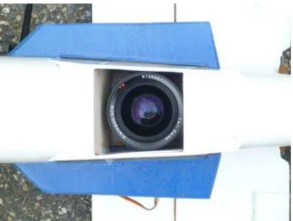
Based on our imaging requirements, the camera and lens combination that we chose weighs about 700 grams. In terms of commercially available UAV systems, this is a relative large camera, both in volume and weight. Most small off-the-shelf systems carry only smaller, sometimes lower resolution cameras.
The camera chosen was a Samsung NX1000 mirrorless camera with a Carl Zeiss 18 mm focal length lens. The Samsung NX1000 is a consumer grade camera with a 20 megapixel CMOS APS-C format sensor (23.5 mm x 15.7mm). It has a shutter capable of 1/4000 of a second and tests show that it can fire repeatedly approximately every 0.8 second.
The Zeiss Distagon 18mm, f4 lens was designed for 35mm film cameras (36 mm x 24 mm frame) and when used with the APS-C sensor, only the central portion of the image projected by the lens is used. This reduces vignetting as well as producing a sharper image. The lens is used at a fixed focus (chosen as the hyperfocal distance for maximum depth of field). The aperture was fixed at f5.6, which is more-or-less at the sweet spot for sharpness across the field of view. This further reduces vignetting without creating diffraction effects. Information about the performance of particular consumer camera/lens combinations can be found on the Web (http:/photozone.de).
Other means employed to make this consumer camera be more “metric-like” included: turning off piezoelectric sensor cleaning, and stabilizing the camera lens mount.
2.2 Fixed-wing or Rotary-wing?
There are a variety of aircraft configurations, from fixed-wing to rotary-wing, which can be used for aerial photography purposes. Factors to be considered when deciding on the best configuration are:
load carrying capacity - weight and volume
flight speed
flight stability
flight range - distance covered
operating environment - take-off and landing area
physical size
durability and maintainability
costThe size of the camera combined with the need to cover up to one, or more, square kilometres for mapping purposes limits our choice of airframes to a fixed-wing configuration. The advantages of a multi-copter, being able to take off and land vertically, and to hover, are negated by its limited range. The disadvantage of a fixed-wing aircraft is the space required for take-off and landing, but this is less of an issue when mapping larger areas, where generally, open spaces are available for take-off and landing. Take-offs are less of an issue, as a fixed-wing aircraft can be hand-launched from a small space.
Additionally, multi-copters are more complex in many ways. The propulsion system requires at least three motors and their associated electronics. They are difficult to fly manually without computer stabilization. A motor failure is often catastrophic because unlike a fixed-wing aircraft, a multi-copter cannot glide to a landing. The complexity translates to more maintenance and higher costs.
2.3 What Kind of Fixed-wing?
Once the UAV platform was narrowed to a fixed-wing aircraft, there was the choice of the fixed-wing configuration. The two main options are flying wing or regular configuration with a tail. There are advantages and disadvantages to each.
The flying wing is physically more compact and harder to damage. However, it is less stable (more sensitive to centre-of-gravity location), has a higher stall speed (must fly faster), is harder to configure to carry a bulky camera, and is less visible in the air due to its small profile.
Typically, a flying wing is harder to hand launch, requiring a catapult system. This is due to a number of reasons. First is the lack of a fuselage which provides for an easy location to grip the airframe. Second is the propeller, which typically is at the rear of the airframe, is in a good position to make contact with the launcher’s hand. Thirdly, the wing’s high stall speed makes it difficult to achieve minimum flying airspeed with a hand launch.
The wing’s high stall speed also makes landing difficult. The high landing speeds leaves the aircraft susceptible to damage The International Archives of the Photogrammetry, Remote Sensing and Spatial Information Sciences, Volume XL-1/W4, 2015
once it contacts the ground. The damage can be accepted as a cost of using a flying wing or a landing system, such as a parachute, may be implemented to avoid high speed landings (Brucas, 2013).
Installation of landing gear on a flying wing is also difficult. This exposes the downward facing camera to the risk of damage as every landing is a belly landing.
An aircraft, with a tail, is more stable than a flying wing. It is larger, so is more easily configured to carry a bulky camera. Also, landing gear can be easily added to protect the camera lens. However, the airframe is more susceptible to damage because of the added fuselage and tail. An important bonus of the larger shape, though, is increased visibility at a distance, which is important when aircraft is at the limits of eyesight.
The size (wing area and total weight) of an airplane is an important determinant of its flight characteristics. Generally, an airplane with a lighter wing loading (total weight / wing area) can fly slower (lower stall speed). Additionally, a larger airplane (more wing area) with the same wing loading as a smaller airplane will be easier to fly. This scale effect can be quantified by the Wing Cube Loading formula (WCL = Weight / Area1.5 where Weight is in ounces and Area is in square feet) (Reynolds, 1989).
An aircraft with a Wing Cube Loading of less than 10 would be desirable. Such an aircraft is suitablefor use as a sport model for radio-control pilots. It would also be suitable as an UAV because its relatively slow and stable flight characteristics.
2.4 The Study UAV
2.4.1 System Overview
BEVRC Skywalker 1.9 metre wingspan fixed wing aircraft of EPO foam
commercially available kit; requires building
single electric motor
ailerons, flaps, rudder, elevator, motor speed control
fuselage modified to carry camera payload (700 grams)
landing gear added to the aircraft to raise the fuselage and camera above the ground when landing
optional flaps were installed in the wing to slow down the landing speed. Also allows steeper descent into a tight landing zone
total flying weight of 2.7 kg (95 ounces); payload: camera weighing 700 grams; area = 45.2 dm2 (4.87 sq. ft.); WCL = 95 / 4.871.5 = 8.84
Ardupilot APM 2.6, GPS, 3D accelerometer, barometer, digital compass, magnetometer, airspeed sensor
full duplex telemetry radio system
Spektrum DX8 radio control system
lithium polymer batteries - 4S 4000mAH
20 minutes flight time, at 14 m/s, about 17 km rangeFigure 1. The Study UAV
This aircraft has low wing loading, good stability, low stall speed, good load carrying capacity, and is durable. It easy to hand launch, has a good power-to-weight ratio with a good rate of climb, and can land at a low airspeed in a short distance with flaps deployed. It cruises at 14 m/s and can land with full flaps at 10 m/s.
Flying this aircraft does require radio-control piloting skills and construction requires hands-on building, system integrating, and troubleshooting. However, these skills are also required in the long term operations of an UAV.
2.4.2 Airborne Components
The airborne components of the UAV system consist of the airframe, electric propulsion system, radio control electronics, autopilot, telemetry radios, and camera. These components work together to perform the function of taking photographs of the ground from pre-planned positions in space. The autopilot, an Ardupilot APM 2.6, is the part that pulls everything together. It controls the airplane and the camera when it is flying the lines over the ground to be photographed.
The autopilot's primary task is to fly the airplane along a preplanned flight path. It does this autonomously, without any human input. A prerequisite for this is an airplane that is trimmed to fly straight and level with minimal control input. An autopilot may be able to fly a badly trimmed airplane but its performance in flying a precision pattern is compromised.
The autopilot takes input from various sensors to control the flight. It flies the UAV to waypoints using GPS for navigation. The real-time control of the UAV is dependent on a three dimensional accelerometer, magnetometer, barometer, and air speed sensor for feedback.
The autopilot is controlled by the pilot on the ground through the radio control system. The autopilot has several modes including:
Manual - control is by the pilot through the radio control transmitter
Stabilize - pilot controls the airplane but the autopilot will recover to level flight if pilot releases the control sticks
Fly-by-Wire - pilot controls the airplane but the autopilot modifies the commands so the pilot "steers" The International Archives of the Photogrammetry, Remote Sensing and Spatial Information Sciences, Volume XL-1/W4, 2015the aircraft. For example, a constant aileron input will bank the aircraft to a fixed bank angle instead of increasing the bank angle while aileron input is present.
Loiter - circle at a position at a fixed height above ground
Auto - fly the preplanned mission
Return-To-Launch - return to the initial launch locationFigure 2. UAV autopilot, sensor, and radio packages
The pilot can switch to different autopilot modes using the radio control transmitter. The pilot can, at any time, switch to Manual mode and take control of the UAV. All missions are flown with the UAV in sight of the pilot on the ground so he is in control at all times.
2.4.3 System Integration
The components of the UAV system must be assembled, installed and configured before it is operational. The three main components are the UAV, the ground control system, and the data processing system.
UAV
The airframe was assembled with modifications made to accommodate the camera. The aircraft’s fuselage, in stock form, was not wide enough to house the camera. Structural modifications were required to mount the camera so it takes images in landscape format while in flight. This maximizes the distance possible between parallel flight lines.
Next, the electric propulsion, radio control, and autopilot systems were installed. At this point, the aircraft is capable of flight under manual control and flight tests were carried out. These tests require a pilot who is competent in flying radio control airplanes.
The flight tests were carried out so the aircraft can be properly trimmed for level, stable flight and to verify performance. A dummy load of 700 grams, to mimic the camera payload, was
mounted in the aircraft to test performance with the planned gross weight.
After the aircraft's performance was confirmed to be satisfactory, the autopilot tuning process began. There are two steps in this procedure. The first part is to configure to autopilot to fly the aircraft in a stable manner while maintaining a constant altitude. When this is achieved, the pilot can “steer” the aircraft in a horizontal plane without worrying about manipulating the throttle and elevator.
After the autopilot was tuned for stable flight, it was tuned to follow a flight plan. The flight characteristics of an aircraft vary with a number of factors including weight, balance, power, and airspeed. Performance in level flight is also different from performance in a banked turn. For a fixed-wing aircraft, making a turn without significant overshoot or undershoot while maintaining a constant altitude is the goal of the autopilot tuning. The aircraft's capabilities, such as its minimum turn radius, must be considered during the tuning process.
The camera shutter is controlled by the autopilot. The autopilot is programmed to capture an image at a set distance along a flight line. This ensures that the image overlap is maintained even when the ground speed varies as the aircraft is flying at a constant airspeed in varying wind conditions. The Samsung camera has a USB interface which allows remote triggering of its shutter and this is operated by the autopilot through an electronic relay via a custom USB cable. Information needed to interface this particular camera with the APM autopilot was gleaned from various Web sources.
Figure 3. UAV Payload – Samsung NX1000 with Carl Zeiss 18mm lens
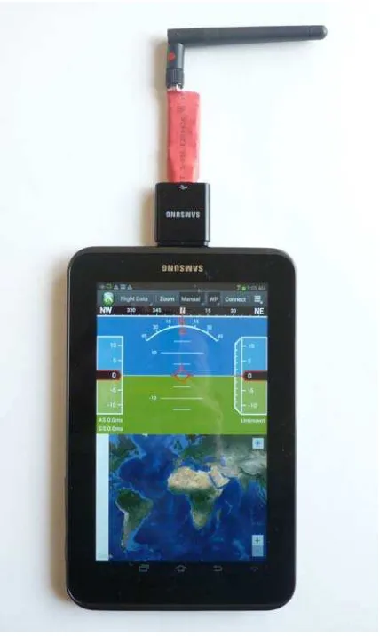
Ground Control System
The ground control system consists of an Android pad computer with a 3DR 915 Mhz telemetry radio running Droidplanner software. This ground control computer can be used to upload flight plans to the autopilot and also to monitor the aircraft remotely while it is in the air. The performance of the UAV is monitored in real-time on the pad computer, with parameters such as airspeed, elevation, roll, pitch, GPS status, and battery condition displayed. The flight plan is shown and the UAV’s current position is plotted relative to the flight plan. It can also The International Archives of the Photogrammetry, Remote Sensing and Spatial Information Sciences, Volume XL-1/W4, 2015
be used to issue commands to the autopilot, such as Return-To-Launch, while the aircraft is airborne.
Droidplanner software is free and open source (https://github.com/arthurbenemann/droidplanner/).
Figure 4. Ground Control System with 915MHz 3DR radio running Droidplanner
Flight Planning
Mission Planner software is used to plan the UAV flights. It is free software by Michael Oborne and it allows you to graphically design flight-lines and generate autopilot command files. This software can also be used to configure the APM autopilot. Mission Planner is available for free (http://planner.ardupilot.com/).
Figure 5. Mission Planner
Mission Planner software generates parallel flight-lines which are flown in order in a zig-zag pattern. This works well if the aircraft can turn 180o in the distance between adjacent flight-lines. If the aircraft’s minimum turning diameter is greater than the line spacing, its turns will be wider than the flight line spacing and the flight lines will not be flown accurately. This problem can be solved by extending the flight lines beyond the area of interest to allow the aircraft to get back on line, or the lines may be flown in an interleaved pattern with larger diameter turns.
Our aircraft can follow the zig-zag flight pattern if the separation between flight-lines is greater than 60 metres. Our typical missions require flight-line spacings in the range of 20 metres, so an interleaved pattern is used which consists of flying a series of oval circuits over the project area.
UGL has developed software to automate the calculation of the flight-line order so that the minimum distance is flown. The zig-zag flight line files, as generated by Mission Planner, is processed by the software and it reorders the flight lines so the required turning minimum turning diameter is achieved. The software will also try all possible combinations to minimize flying distance.
Two flight plans are generated for each photo mission with the flight-lines in one plan at 90⁰ to the flight-lines in the other plan. The actual plan used will be the one that places any prevailing wind perpendicular to the flight-lines. Tail winds are to be avoided as the aircraft’s increased ground speed requires a shorter camera exposure to avoid image blur, and the time between images decreases which may cause the camera to miss photos. The flight plan is loaded to the autopilot on site after the wind conditions are assessed.
Data Processing
Agisoft PhotoScan Professional software is used to process the aerial photographs. This software performs photogrammetric bundle adjustments and produces a Dense Surface Model (DSM). The process is largely automatic and requires minimal user intervention.
Figure 6. 3D perspective view of 60 million point DSM generated from 985 photos in Agisoft PhotoScan
The computer used for processing is equipped with a high performance graphics processor card. The specialized Graphics Processor Units (GPU) are required to process the large amount of data in reasonable times.
3. RESULTS
The UGL UAV system has been tested in the field and the photogrammetric results have been compared with results of ground based Global Navigation Satellite System (GNSS) survey. The test was a stockpile survey. Two independent flights were flown with 11 independent targeted control points for each flight. The control was created by conventional GNSS survey using Trimble R8's
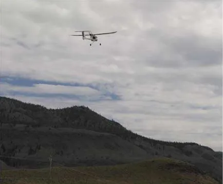
Figure 7. Study UAV during autonomous flight
Each flight resulted in over 250 photos covering an area 420 metres by 360 metres. The stock pile has a flat top, 120 metres above ground. Photographs were taken at a height of 90 metres above the top with 75% overlaps, forward and side. This worked out to 30 metre spacing between lines with 20 metres between photographs along the line. Each image pixel covered approximately 25 millimetres of the ground.
Dense Surface Models (DSM) were created from each flight. Photogrammetric bundle adjustments and Dense Surface Model (DSM) computations of the images were done in an automated manner using Agisoft PhotoScan Professional (version 1.0.4).
The 3D error at control points compared to GNSS was about one pixel and the mean distance between both DSM surfaces was 0.032±0.024 metres [Cryderman, 2014].
The Underhill UAV has been flown in test flights and actual photography missions and its capabilities have determined from actual experience. For photogrammetric results of ground pixel size of 25 millimetres, this UAV can cover an area of approximately 600 metres by 500 metres, with approximately 23 metres between flight-lines. This will take a flying time of approximately 20 minutes and approximately 18 kilometres in distance will be flown.
These are realistic maximum mission parameters and they are limited by the energy capacity of the Lithium polymer batteries powering the UAV and human line-of-sight range. In Canada, UAVs may not be flown beyond the pilot's line-of-sight with the unaided eye.
4. FURTHER DEVELOPMENTS
Real Time Kinematic (RTK) GPS is becoming a reality for UAVs. By having a RTK receiver onboard the UAV communicating with a base receiver on the ground, the position of the UAV as it is taking each photograph can be measured to an accuracy of several centimeters. This will provide real benefits for photogrammetry as it can greatly reduce the amount of ground targets required to control the photography (Lapine, 1996). In theory, ground control can be eliminated but it is prudent to have a minimal number of ground control points to guard against blunders and for quality control. As ground control is a large component of field costs, using RTK for control is a big step forward.
Figure 8. GNSS RTK rover for Study UAV. Dual frequency, GPS/GLONASS, synchronized camera event recording
The components required for a small UAV RTK system are now available. There are a number of Original Equipment Manufacturer (OEM) RTK GPS boards and antennae which are small and light enough to be carried by a small UAV.
UGL has built a prototype airborne RTK unit with a complete weight of about 170 grams. This includes the basic dual frequency GPS/GLONASS GNSS receiver module, antenna, radio for RTCM 3.0 corrections, autopilot interface (for shutter The International Archives of the Photogrammetry, Remote Sensing and Spatial Information Sciences, Volume XL-1/W4, 2015
trigger), Arduino based data logger, and battery. The basic receiver module is 85mm x 22mm x 53mm. The complete system is easily carried by UGL's UAV. This system is now in the test phase.
5. REGULATORY CONSIDERATIONS
UAV flights by non-commercial and non-military users have increased dramatically in the last few years and governments are scrambling to regulate UAV use. The regulations are aimed mainly at commercial users, and in Canada, the regulatory body, Transport Canada, has introduced regulations which govern the commercial use of UAVs. These regulations are aimed at keeping UAVs from endangering people and property both on the ground and in the air
(
Transport Canada, November 2014).In Canada, commercial UAVs must be operated within line-of-sight of the pilot. This limits the distance a small UAV may be flown from the pilot to 400 metres to 500 metres. The pilot must be in control of the UAV at all times. The pilot will be monitoring the flight when the autopilot is flying the UAV and be ready to take control. The pilot must also be knowledgeable about the applicable laws, full scale flight procedures, and flight systems. Additionally, the UAV must have $100,000 of liability insurance (Transport Canada, August 2014).
Transport Canada requires UAV operators obtain a Special Flight Operations Certificate (SFOC) for commercial flights. Operators apply for SFOCs by submitting a plan which describes all aspects of the flight operations and demonstrates that they have the ability and systems in place to conduct safe UAV operations. The company’s flight operations include training, maintenance, procedures, and documentation. Approval of the plan and issuance of a SFOC can take several weeks.
Under specific conditions, there are exemptions from this requirement (Transport Canada, November 27, 2014). In general, the exemptions apply to UAVs not heavier than 25 kg operating in uncontrolled airspace (Class G) more than 5 miles from any aerodrome or built up area. There are other conditions but the exemptions are aimed at UAV operations in airspace where the risk to people, property, and aircraft is low.
Transport Canada is still developing the UAV regulations and it has indicated that the current regulations for UAVs weighing 25 kg or less are a temporary measure and that changes are proposed for 2016 (Transport Canada, May 2015). These proposed changes will address aircraft registration, personnel training, and flight rules.
One regulatory area that the government may touch and would affect the UAV DIYer is certification. Full scale aircraft must be certified to be airworthy and have maintenance procedures to ensure its continuing airworthiness. As a DIYer, it is important that documentation for all components of the UAV is kept and logs for the flights and maintenance of the UAV are kept. It may be necessary to prove to a regulatory body that your UAV is airworthy and safe to fly. On the other hand, the DIYer should be knowledgeable about the aircraft and be capable of maintaining it.
6. CONCLUSIONS
Building your own UAV system for aerial photography/ photogrammetry offers many advantages over buying a turnkey solution. You can save a lot of money, gain detailed knowledge of your system so you can service it yourself or upgrade it in the future, and not be tied to a specific vendor. However, to reap these advantages, you must understand an array of technologies and be able to integrate them into a functioning system.
In the field of fixed-wing UAVs, there is the choice of flying wing or conventional airframe with fuselage and tail. We chose to implement a conventional airframe despite evidence that a flying wing configuration is more efficient (Brucas, 2013). Our experience has shown that the main disadvantage of a conventional airframe, aerodynamic efficiency and endurance, is not an issue due to regulatory limitations in Canada which limits flights to line-of-sight. The line-of-sight limitation negates the requirement for extreme endurance. Meanwhile, the big disadvantage of the flying wing, high stall speed, is avoided so launching and recovery do not require additional complex systems such as catapults and parachutes.
In the early part of the last century, land surveying utilized low-technology tools and required a high level of user involvement, both physically and mentally. That meant that surveyors out in the field were self-sufficient and could be away in the wilderness for months. By the end of the last century, the level of technology had risen substantially while the user effort required had dropped, but the two were still relatively in balance. Today, survey technology, in the form of UAVs and photogrammetry, has drastically upped the technology level while relieving the surveyor of physical and mental efforts.
The UAV mapping technology when viewed as a black-box solution has many problems aside from buy-in costs. The user is shielded from the technology and is told that it is easy to use. This is true if everything is working perfectly. The individual components – computers, camera, radios, and aircraft – are not leading edge, and in fact, they are quite common these days. However, because they must work together, the probability for a system failure becomes more significant.
This is particularly true when the weakest link in the chain, the UAV itself, does its work in the open air, subject to varying physical conditions. The UAV, while controlled by the autopilot, is operating at its highest risk level and is vulnerable to damage. The risk is controlled to acceptable levels when the flight is monitored by a competent pilot who is experienced in flying radio-controlled aircraft and is ready to take over flight control. If the pilot is merely monitoring and relying on programmed routines to fly the aircraft back to the launch point and auto-land, then the probability of aircraft damage increases significantly.
While the UAV mapping technology is being treated as a black-box solution that is fool-proof, it is evident that it is not without risk. When UAVs are used in its logical environment, mapping uninhabited areas away from urban areas, then reliability becomes an issue. Being able to trouble-shoot and fix system The International Archives of the Photogrammetry, Remote Sensing and Spatial Information Sciences, Volume XL-1/W4, 2015
problems in a timely manner with minimum access to service centres is necessary. This is where a DIY UAV system operated by its builders has a distinctive advantage over a turnkey system.
UAVs for aerial photography have been promoted as the new way to map large areas efficiently. Tests have shown that to be true. The cost of the technology is comparable to that of GNSS survey and the results are comparable with much greater resolution. This is a major leap forward.
However, there are risks in UAV technology that are not inherent in the GNSS technology. When these risks are factored in, the advantages of UAVs are not as great. This is particularly true with the turnkey UAV packages operated by people with minimal training.
Building your own UAV system reduces these risks considerably. Coupled with a pilot who is able to fly the UAV to a safe landing when the autopilot fails, an UAV system becomes very competitive. This approach differs greatly from the turnkey system approach where minimum system knowledge is required.
The increasing numbers of UAVs, both hobbyist and commercially operated, has governments scrambling to regulate their use. In Canada, Transport Canada is the regulatory body. Where UAV flights place people, property, or full scale aircraft at risk, the operator must receive from Transport Canada a Special Flight Operations Certificate (SFOC). In order to receive an SFOC, the operator must show that it can safely operate the UAV. Knowledge of flight operations and systems is required.
Using the UAV technology effectively for mapping requires special skills. The move towards “black boxes” for surveying has become the norm. UAVs may become “black boxes” in the future but it is not yet there. However, those who understand and build their own systems will be able to deploy them effectively and economically.
REFERENCES
Brucas, D., Suziedelyte-Visockiene, J., Ragauskas, U., Berteska, E., Rudinskas, D., 2013. Implementation and Testing of Low Cost UAV Platform for Orthophoto Imaging. International Archives of the Photogrammetry, Remote Sensing and Spatial Information Sciences, Vol. XL-1/W2, 2013 UAV-g2013
Coyle, Thomas, 2015. DIY Drones at 64,000 members! http://diydrones.com/profiles/blogs/diy-drones-at-64-000-members
Cryderman, C., Mah, B., Shufletoski, A., 2014. Evaluation of UAV Photogrammetric Accuracy for Mapping and Earthworks Computations. GEOMATICA, Vol. 68, No. 4, 2014, pp. 259-271
Karakis, S., Sefercik, U. G., Bayik, C., 2011. Data Acquisition Through the Model Aircraft for Mapping Services.
International Archives of the Photogrammetry, Remote Sensing and Spatial Information Sciences, Vol. XXXVIII-4/W19
Lapine, L.A., 1996. Airborne kinematic GPS positioning for photogrammetry: The determination of the camera exposure station.
http://www.ngs.noaa.gov/PUBS_LIB/AirborneKinematicGPSP ositioningforPhotogrammetry.pdf
Mészáros, J., 2011. Aerial Surveying UAV Based on Open-Source Hardware and Software. International Archives of the Photogrammetry, Remote Sensing and Spatial Information Sciences, Vol. XXXVII-1/C22
Morin, Brit, 2013. What Is the Maker Movement and Why Should You Care? http://www.huffingtonpost.com/brit-morin/what-is-the-maker-movemen_b_3201977.html
Reynolds, Francis, 1989. Model Design & Technical Stuff:
Wing Cube Loading (WCL) http://www.theampeer.org/CWL/reynolds.htm
Sollenberger, Roger, 2014. From The Economist, Chris Anderson on Drones: A Short History, Long Future http://3drobotics.com/2014/09/economist-chris-anderson-drones-short-history-long-future-long-tail/
Transport Canada, May 2015. Notice of Proposed Amendment (NPA): Unmanned Air Vehicles, CARAC ACTIVITY REPORTING NOTICE #2015-12
Transport Canada, November 27, 2014. AC 600-004 - Advisory Circular: Guidance Material for Operating Unmanned Air Vehicle System under an Exemption
Transport Canada, August 2014. TP 15263E - Knowledge Requirements for Pilots of Unmanned Air Vehicle Systems UAV 25 kg or less, Operating within Visual Line of Sight, First Edition
Transport Canada, November 2014. SI 623-001 - Staff Instruction – Review and Processing of an Application for a Special Flight Operations Certificate for the Operation of an Unmanned Air Vehicle (UAV) System
Wired Staff, 2012. Wired Editor-in-Chief Chris Anderson Steps Down to Run Robotics Startup
http://www.wired.com/2012/11/wired-editor-in-chief-chris-anderson-steps-down/