128 x 40 Mono OLED Column / Row
Driver with Controller
LD7032
1. REVISION HISTORY
Jun. 2008
-First version 1.0
Dec. 2008 -an addition : page7. or floating
- deleted "When IXS=H, CSB must be Low" in page7 - AC Table : VDD = 1.65 ~ 3.5V (page24,26,27)
2.0
DATE CONTENS
PART 1 CONTENTS
1. REVISON HISTORY ...2
2. FEATURES ...4
3. BLOCK DIAGRAM ...5
4. PIN DESCRIPTION ...6
5. FUNCTIONAL DESCRIPTION ...8
5.1. MPU Interface ... 5.2. Dot Memory Map ...…... 5.3. Correspondence Memory and Display ... 5.4. Output Arrange ... 5.5. Data Write / Read Sequence ... 5.6. Dot Matrix Output Wave Form ... 5.7. Pre-charge ... 5.8. Power Save... ... ... 5.9. Reset... 5.10. OSC ... . .. ... 5.11. Frame Sync Signal(F_SYNC) . .. .... ... .. ... ... .. ... ... 5.12. Interface Mode 6. Referential Set-up Flow ...20
6.1. Power ON-OFF ... 7. ELECTRICAL CHARACTERISTICS ...20
7.1. MAXIMUM RATINGS ...
7.2. DC CHARCTERISTICS ...
7.3. AC Characteristics ...
7.3.1.1(2) Parallel Interface ...
7.3.2.1(2) Serial Interface ...
7.3.3. I2C Interface ... .. ...
7.3.4. Driver OUTPUT .... ... ... ...
2. FEATURES
Power Supply
VDD : 1.65 ~ 3.5V
VCC_C : 8.0 ~ 16.0V for Column VCC_R : 8.0 ~ 16.0V for Row
Display Area
Max 128 x 40 Line
Graphics RAM
Dot matrix : 128 x 1 Bit x 40 = 5,120 Bit
Column Driver Max 128 Outputs Mono
Maximum Output Current = 255 uA (1 uA Step) Next Pin to Pin Current Deviation ±2.0 (Iout = 50uA) Current Deviation at 1Chip Max-Min ±4.0 % (Iout = 50uA)
Average Current Deviation against absolute level ±6.0% (Iout = 50uA) 5 Times Peak boot Current Driving
Row Driver
Max 40 Outputs
Variable duty ratio (1 to 40) ON resistance typical 25ohm
CPU Interface
8080 or 6800 series parallel interface
Serial Peripheral Interface
I2C Serial Interface
Screen Saver
Screen Saver Function.
Oscillator
On-chip RC oscillator
Frame Rate
Variable Frame Rate (60,75,90,105,120,135)Hz
Crosstalk
Crosstalk enhancement function
Internal regulator for row driver
3. BLOCK DIAGRAM
er R0-R39
VDD VCC_C
4. PIN DESCRIPTION
4. 1. Power Supply Pins
4.2. System Interface Control Pins
OELD Dot Matrix Power Supply for Column Driver
VCC_C
Power
Ground pin.
VSS
(AVSS/AVSS)
Analog and digital voltage supply.
VDD
OELD Dot Matrix Power Supply for Row Driver
If Internal Regulator for Row Scan is active, this pin is the power output pin of internal row power regulator. A 4.7uF capacitor is recommended to connect between VCC_R and VSS. If internal row power regulator is disabled, it must be connected to the external high voltage source or VCC_C.
VCC_R
Function TYPE
Signal
H: Parallel L: Serial I
PS
H : I2C is selected, L : I2C is not selected I
IXS
H: 68CPU L: 80CPU I
C80
Function TYPE
Signal
1 0
Serial I2C
0 0
Serial SPI
X 1
Parallel
IXS PS
4.3. MPU Interface Pins
OELD Dot Matrix Column Output O
C0 to C127
OELD Dot Matrix Row Output O
R0 to R39
Function TYPE
Signal 4.4. OLED Driver Pins
Frame Sync Signal O
F_SYNC
Pre-Charge Voltage O
PRE
These pins configure I2C interface address. Using these
pins, I2C Address can be selected.
I ID2~ID0
This pin is the dot output current reference pin. IDOT is derived from Iref. A resister should be connected between this pin and VSS .
( Current Setting. Typ Resistance = 39 kΩ) ( Current adjustable range ±30%) O
IREF
Test Pin.
This pin should be tied VDD or VSS in normal operation. I
EXT_CLK
These are 8-bit bi-directional data bus to be connected to t he microprocessor’s data bus.
When I2C interface mode is selected, D1 will be the I2C d ata input (SDA) and D0 will be the I2C bus clock input (S CL), and D2 ~ D7 should be tied VDD or VSS.
When serial interface mode is selected, D1 will be the seria l data input (SDIN), D0 will be the serial clock input (SCL K), and D2 ~ D7 should be tied VDD or VSS or floating. I/O
D7~D0
Address ( L: command, H: Parameter) I
A0
Reset (Active Low) I
RSTB
Write ( Active Low, 80 Interface) H:Read L:Write (68 Interface) I
WRB/RW
Read ( Active Low, 80 Interface) Enable (68 Interface)
I RDB/E
Chip Select ( Active Low) I
CSB
Function TYPE
5. FUNCTIONAL DESCRIPTION
5.1 MPU Interface
5.1.1. 80 Series Interface
Parameter or Data H
H L
Read Parameter or Data
Parameter or Data H
H L
Write Parameter or Data
Command L
H L
Write Command
D[7:0] A0
RDB WRB
CSB Function
Command 1’st Parameter/Data 2’nd Parameter/Data
CSB A0
WRB/RDB
D[7:0]
※NOTE :
↑stands for rising edge of signal. L stands for low in signal.
5.1.2. 68Series Interface
Parameter or Data H
↓
H L
Read Parameter/Data
Parameter or Data H
↓
L L
Write Parameter/Data
Command L
↓
L L
Write Command
D[7:0] A0
E RW
CSB Function
Command 1’st Parameter/Data 2’nd Parameter/Data
CSB A0
E
D[7:0] RW
D[1] H
D[0] L
Write Parameter/Data
D[1] L
D[0] L
Write Command
DATA A0
CLOCK CSB
Function
CSB
A0
Command
SID(D1)
Parameter/Data
D4 D3 D2 D1 D7 D6 D2 D1
D7 D6 D5 D4 D3 D0 D7 D6 D5 D0
SCLK(D0)
Data Latch Data Latch
※Notice
- All command inputs have a priority over previous commands. - To select Parallel/Serial Interface use PS Input. (H: Parallel L: Serial) - Serial clock (SCLK) works in the unit of 8 clocks.
5.1.4. I2C Interface
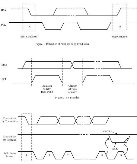
The bidirectional I2C bus consists of the serial clock (SCL) and serial data (SDA) lines. Both lines must be connected to a positive supply through a pull-up resistor when connected to the output stages of a device. Data transfer may be initiated only when the bus is not busy.
I2C communication with this device is initiated by a master sending a Start condition, a high-to-low transition on the SDA input/output while the SCL input is high (see Figure 1). After the Start
condition, the device address byte is sent, most significant bit (MSB) first, including the data direction bit (R/W).
After receiving the valid address byte, this device responds with an acknowledge (ACK), a low on the SDA input/output during the high of the ACK-related clock pulse.
On the I2C bus, only one data bit is transferred during each clock pulse. The data on the SDA line must remain stable during the high pulse of the clock period, as changes in the data line at this time are interpreted as control commands (Start or Stop) (see Figure 2).
A Stop condition, a low-to-high transition on the SDA input/output while the SCL input is high, is sent by the master (see Figure 1).
Any number of data bytes can be transferred from the transmitter to receiver between the Start and the Stop conditions. Each byte of eight bits is followed by one ACK bit. The transmitter must release the SDA line before the receiver can send an ACK bit. The device that acknowledges must pull down the SDA line during the ACK clock pulse so that the SDA line is stable low during the high pulse of the ACK-related clock period (see Figure 3). When a slave receiver is addressed, it must generate an ACK after each byte is received. Similarly,
the master must generate an ACK after each byte that it receives from the slave transmitter. Setup and hold times must be met to ensure proper operation.
SDA
SCL
S P
Start Condition Stop Condition
Figure 1. Definition of Start and Stop Conditions
SDA
SCL
Data Line Stable; Data Valid
Figure 2. Bit Transfer Change of Data Allowed
Data output by Transmitter
Figure 3. Acknowledgement on I2C Bus Data output
by Receiver
SCL From
Master 1 2 8 9
NACK
ACK
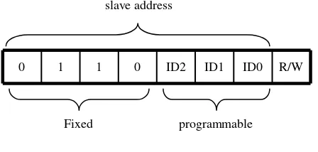
- I2C Device ID Address
Following a START condition, the bus master must output the address of the slave it is accessing. The address is shown in Figure 4. To conserve power, no internal pull-up resistors are incorporated on the hardware selectable address pins and they must be pulled HIGH or LOW.
0 1 1 0 ID2 ID1 ID0 R/W
slave address
Fixed programmable
The last bit of the address byte defines the operation to be performed. When set to logic 1 a read is selected, while a logic 0 selects a write operation.
MSB bit is first transfered.
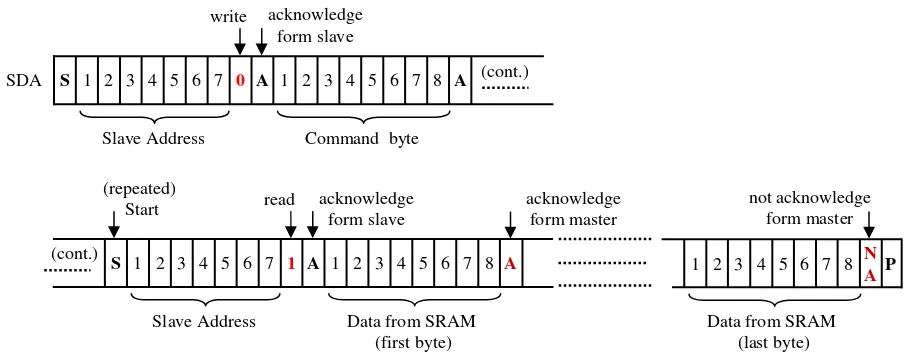
- I2C Bus Transactions
Figure 4. Device ID Address
SDA S 1 2 3 4 5 6 7 0 A 1 2 3 4 5 6 7 8 A 1 2 3 4 5 6 7 8 A P SCL
Slave Address Command byte Data to Parameter register acknowledge
form slave
acknowledge form slave
Figure 5. Write Single Parameter Command write
Stop or Repeat Start
SDA S 1 2 3 4 5 6 7 0 A 1 2 3 4 5 6 7 8 A 1 2 3 4 5 6 7 8 A 1 2 3 4 5 6 7 8 A P SCL
Slave Address Command byte parameter to register (first byte)
parameter to register (last byte) acknowledge
form slave
acknowledge form slave
Figure 6. Write Multi Parameter Command write
Figure 7. Read From SRAM A
8 7 6 5 4 3 2 1 A
0
7 6 5 3 4 2 1 S
Slave Address Command byte acknowledge
form slave write
8 6 4
2 N
A
7 5 3 1
not acknowledge form master
P
SDA (cont.)
A
8 7 6 5 4 3 2 1 A
1
7 6 5 3 4 2 1 S
Slave Address Data from SRAM (first byte) acknowledge
form slave read
(cont.)
(repeated)
Start acknowledge
form master
5.2 Dot Memory Map
Memory Size = 16 x 8Bitx40 = 5,120 Bit (00,00) (01,00) (00,01) (01,01)
(02,00) (02,01)
(0E,00) (0E,01)
(0F,00) (0F,01)
(00,26) (01,26) (00,27) (01,27)
(02,26) (02,27)
(0E,26) (0E,27)
(0F,26) (0F,27)
00h 01h 02h 0Eh 0Fh
00h 01h
26h 27h
Column Memory X Address
R
o
w
M
e
m
o
ry
Y
A
d
d
re
5.3. Correspondence Memory and Display
- “DispStart” command fix the relation of memory and display coordinates. Memory
Reading Start Address
- In scroll mode, display all memory area regardless display size.
Scroll Area
- “DispSize” command indicate active outputs. - The column outputs out of active area always
pre-charge level.
- The row outputs out of active area always VCC_R excluding display off.
- Scan is repeated within active area. - Rows out of active row are VCC_R.
- “DispSize” command don’t use during panel display. Display
Size
- “DispDirection” command indicate Row scan direction.
- Row R0⇔Rmax Display
Direction
- “Data Writing Box” command indicate memory writing area.
- “Writing direction” command indicate writing direction (auto address increment or decrement) Memory
Data Write
(XS,YS)
(XE,YE)
Memory
Display
S
ca
n
D
ir
ec
tio
n
Display
Size
Active Column
A
ct
iv
e
R
o
w
ABCDEFG
Active Column Ac
ti ve R ow
CDEFGAB
Ac ti ve R ow
Left Scroll
A B C D
C D A B
Momory
Start Point
R1 R0
R3 R2
R38
R39
Bumps Face Up
INTERFACE
C0•••••••••••••••••••••••••••••••••••••••••••••••C127 128
Display Face
2020
5.5. Data Write / Read Sequence
DataWrite
WRITE Parameter
END
Dot Data Write
DataRead
READ Parameter
END Dummy Read
Dot Data Read
Serial Interface is impossible to Data Read 5.4. Output Arrange
5.6. Dot Matrix Output Wave Form
Related Command Pre-Charge
Level Column Port Voltage Level
1 Row Period
Pre-Charge
Period Peak Boot
Period
Data Display Period Peak Delay
Period
Pre-Charge Period
Peak Delay Period
Peak Boot Period
Data Display Period 1 Row Period
Row(N)
Column Port Output Waveform
Row(N+1)
1 CLK
1 CLK
(0,0) (0,1) (1,0) (1,1)
Row Overlap
5.7. Pre-charge
5. 8. Power Save
・Register Clear
・Display-OFF
・Stand-by-ON
・Display-OFF
・OSCA Start/Stop
・Display ON/Off Function
SOFTRES STBON/OFF
DISPON/OFF Command
Dot Matrix
Soft Reset Stand-by
Display ON/OFF Function
5. 9. Reset
When RSTB Input becomes ‘L’, All Register is set Default. When SOFTRES command is inputted, All Register is set Default
5. 10. OSC
!" # $ %
Frame frequency is adjusted by “DFRAME”command
Clock System
OSCADot Matrix Controller
Dot Matrix Memory
Dot Driver
5. 11. Frame Sync Signal ( F_SYNC )
Row(last)
Row(first)
5. 12. Interface Mode (Data Write Only)
Dot matrix display data write mode
(00,00) (01,00) (00,01) (01,01)
(02,00) (02,01)
(0E,00) (0E,01)
(0F,00) (0F,01)
(00,26) (01,26) (00,27) (01,27)
(02,26) (02,27)
(0E,26) (0E,27)
(0F,26) (0F,27)
00h 01h 02h 0Eh 0Fh
00h 01h
26h 27h
Column Memory X Address
R
o
w
M
e
m
o
ry
Y
A
d
d
re
ss
7 6 5 4 3 2 1 0
MSB LSB
1 Address = 8 Pixels
1 1 0 0 1 0 1 0
Memory Display
WriteDirection = 00h, XDispStart = 00h, YDispStart = 00h
1 1 0 0 1 0 1 0
COUT7 COUT0
7 6 5 4 3 2 1 0
MSB LSB
1 Address = 8 Pixels
0 1 0 1 0 0 1 1
Memory Display
WriteDirection =08h, XDispStart = 00h, YDispStart = 00h
1 1 0 0 1 0 1 0
COUT7 COUT0
6. Referential Set-up Flow
6.1 Power ON-OFF
7. ELECTRICAL CHARACTERISTICS
7.1 MAXIMUM RATINGS
(Ta = -40~85℃)
-0.3∼∼∼∼+18.0 VCC_C
℃ -
- -
-50~~~~+125 Storage temperature Range
TSTG
℃ -
-- -40~~~~+85 Operating Temperature Range
TOPR
- --
-0.3~~~~VDD+0.3 Output Voltage Range
VOUT
- --
-0.3~~~~VDD+0.3 Input Voltage Range
VIN
-0.3∼∼∼∼+18.0 VCC_R
V
−−−−0.3~~~~+3.63
Supply Voltage VDD
Unit Value
Parameter content
VDD
VCC_C
VCC_R
OFF
OFF ON
ON Min 0.1ms
Min 0.1ms
0V
0V
VDD
VCC_C VCC_R
RSTB
ON Min 0.1ms
0V
VDD
7.2. DC CHARACTERISTICS
Output Current Evenness *2) Calp1
VCC_R = 0.8*VCC_C
IVCC_R=5mA
VCC_R Power Regulator Output Voltage IRVCC
Operating Voltage for Column VCC_C
Logic Power 1 VDD
ON Resistance Rrg ON Resistance Rr Ioutpeak = 250uA
Peak boot Absolute Correctness *3) Ioutpeak = 250uA
Peak boot Evenness *2) Calp3 Ioutpeak = 250uA
Peak boot
Pin to Pin Evenness *1)
Output Current Absolute Correctness *3) Cchip1
Output Current Pin to Pin Even ness *1) Oscillator Frequency
For Dot Matrix FOSC1
uA +1.0
-1.0 Input Leakage Current
IIL Iout=100uA
Low Logic Output Level VOL Iout=-100uA
High Logic Output Level VOH
Low Logic Input Level VIL
High Logic Input Level VIH
NOTICE:
*4) Iout =10μA, All Data on, Frame Frequency 120Hz, VCC_C=VCC_R=15V, VDD=2.8V, Output( DOT ) all Open, Display Size full, Others Default
UNIT Normal Operation
IVCC_C2
Stand-by Current IVDD1
All Pin Short Each Pin
ILOAD=3mA Pre-Charge SW
ON Resistance Rp Output Level (open-drain) at 3mA sink current
at SDA, SCL ( I2C)
VDD > 2V 0.0 - 0.4 V
VDD< 2V 0.0 - 0.2*VDD
IOL
7. 3. AC Characteristics
7. 3. 1.1 Parallel Interface1 (Write/Read Timing)
Read
Read data hold time ( Data output disable time )
200 Tdsr
Read data setup time ( Data Output Access Time )
10 Tdhw
Write data hold time
20
D0 – D7 Tdsw
Write data setup time
80 Tchr
Read control high pulse time
60 RDB
Tclr Read control low pulse time
40 Tchw
Write control high pulse width
40 WRB
Tclw Write control low pulse width
500 RDB
Tcycr System cycle time
10 A0
Tah Address hold time
20 A0
Tas Address setup time
MAX
MIN Units
Specification Condition
Symbol Parameter
VALID VALID
VALID
Tas Tah
Tcsh
Tdsw Tdhw
Tcsh
Tdsr Tdhr Tah
7. 3. 1.2 Parallel Interface2 (Write/Read Timing)
Read Write
30 CSB
Tcsh
ns 300
WRB Tcycw
CSB – WRB , RDB time
10 Tdhr
Read data hold time ( Data output disable time )
200 Tdsr
Read data setup time ( Data Output Access Time )
30 Tdhw
Write data hold time
60
D0 – D7 Tdsw
Write data setup time
80 Tchr
Read control high pulse time
60 RDB
Tclr Read control low pulse time
120 Tchw
Write control high pulse width
120 WRB
Tclw Write control low pulse width
500 RDB
Tcycr System cycle time
30 A0
Tah Address hold time
60 A0
Tas Address setup time
MAX
MIN Units
Specification Condition
Symbol Parameter
7. 3. 2.1 Serial Interface1
A0 setup time A0 hold time tASS
SCL, CSB CSB
SDI SCL Related Pins
-Conditions
15 SCL to Chip select
tSCC
20 50 50 Chip select setup time
Chip select hold time Chip select high pulse width tCSS
tCSH
tCSW
20 20 Data setup time
Data hold time tDSS
tDHS
66 20 20 Serial clock cycle
High pulse Width Low pulse width tCYS
Input Signal Slope Output Signal Slope
VIH
NOTE : The input signal rise time and fall time (tr, tf) is specified at 15 ns or less. 8 th SCL
7. 3. 2.2 Serial Interface2
ns
-50 60 A0
A0 setup time A0 hold time tASS
tAHS
-MAX
ns ns ns ns Unit
-TYP
SCL, CSB CSB
SDI SCL Related Pins
-Conditions
40 SCL to Chip select
tSCC
60 100 100 Chip select setup time
Chip select hold time Chip select high pulse width tCSS
tCSH
tCSW
60 60 Data setup time
Data hold time tDSS
tDHS
150 60 60 Serial clock cycle
High pulse Width Low pulse width tCYS
tPWH
tPWL
MIN Parameter
Symbol
7. 3. 3 I2C Interface
(VSS = 0V, VDD= 1.65V~3.5V, Ta = 25℃)
Symbol Parameter Standard mode Fast mode Unit
MIN MAX MIN MAX
fscl SCL clock frequency 0 100 0 400 kHz
tBUF bus free time between a STOP and
START condition 4.7 - 1.3 - us
tHD;STA hold time (repeated) START condition 4.0 - 0.6 - us
tSU;STA
set-up time form a repeated START
condition 4.7 - 0.6 - us
tSU;STO set-up time for STOP condition 4.0 - 0.6 - us tSU;DAT data set-up time 250 - 100 - ns
tHD;DTA data hold time 0 - 0 - ns
tVD;ACK data valid acknowledge time 0.3 3.45 0.1 0.9 us
tVD;DAT data valid time 300 - 50 - ns
tLOW LOW period of the SCL clock 4.7 - 1.3 - us
tHIGH HIGH period of the SCL clock 4.0 - 0.6 - us
tf fall time of both SDA and SCL signals - 300 - 300 ns
tr rise time of both SDA and SCL signals - 1000 - 300 ns
tSP pulse width of spikes that must be
suppressed by the input filter 0 50 0 50 ns
tSU;STA tLOW tHIGH 1/fSCL
tf
tr
tBUF
tHD;STA tSU;DAT tHD;DAT tVD;DAT tVD;ACK tSU;STO
SCL
7.3.4. Driver OUTPUT
TRF TRR
0.2 0.8
“RowOverlap” command changes Row falling timing`
ns
Column Peak Falling Delay Time
ns
Column Peak Delay Time
ns Column Drive Start Delay Time
ns Column Falling Time until Row Falling
ns Row Rising Time
ns Row Falling Time
Unit Normal Current
IREF x 5 *1) 0uA Peak Boot Current
1h 0h Gray Scale
7.3.5. Reset
128 x 40 Mono OLED Column / Row Driver with Controller
PART 2 CONTENTS
1. Display System Command ...31 1.1. Software Reset ... 1.2. Dot Matrix Display ON/OFF ... 1.3. Dot Matrix Display Stand-by ON/OFF ... 1.4. Dot Matrix Frame Rate ... 1.5. Graphics Memory Writing Direction ... 1.6. Display Direction ... 1.7. Display Size ... 1.8. Display Start ... 2. Read/Write command ...37 2.1. Data Reading/Writing Box ... 2.2. Dot Matrix Display Data Read/Write ... 2.3. Register Read ... 3. Driver Setting Command ...39
3.1. Peak Pulse Width Set ... 3.2. Peak Pulse Delay Set ... 3.3. Dot Matrix Current Level Set ... 3.4. Pre-Charge Width Set ... 3.5. Pre-Charge Mode Select ... 3.6. Row overlap set ... 3.7. Row SCAN ... 3.8. Row Scan Sequence Setting ... 3.9. Data Reverse ... 4. Others ...43
5. Optional Command ...44 5.1. IC Test Co mmand ... 5.2. Set Internal Regulator for Row Scan ... 5.3. Aging Mode Set ...
5.4. Set XTALK Enable ... ... ... .. ... .. ... ... 5.5. Set VDD Selection ... ... ...
INSTRUCTION DESCRIPTION
1. Display System Command1.1 Software Reset
- Software reset command
- All registers are cleared default. *1) - Dot matrix is OFF.
- OSCA is stopped
*1) Don’t clear Graphics memory
1.2. Dot Matrix Display ON/OFF
- When D0=”0” :
Turns the dot matrix Display OFF (Default). Display OFF means
All Column Output become Pre-charge level. All Row Output become VSS.
Stop Data transfer from memory to Dot Matrix Driver.
- When D0=”1” :
Turns the dot matrix Display ON.
1.3. Dot Matrix Display Stand-by ON/OFF
D=0 : Stand-by OFF D=1 : Stand-by ON
- When D0=“0”
OSCA Start. (Don’t turn the dot matrix display on)
- When D0=”1”
Execute DDISPOFF command OSCA Stop. (Default).
*NOTE 1 : Don’t clear Graphics memory and Register.
*NOTE 2 : After software and hardware Reset, stay “DSTBYON” Mode. *NOTE 3 : Column Driver latched datas are reset.
INSTRUCTION Command
WR A0 D[7:0]
Parameter
WR A0 D7 D6 D5 D4 D3 D2 D1 D0
Parameter Definition Default
DDISPON/OFF W L 02h W H - - - D0 D=0 Dot Matrix Display OFF
D=1 Dot Matrix Display ON 00h SOFTRES
INSTRUCTION Command
WR A0 D[7:0]
Parameter
WR A0 D7 D6 D5 D4 D3 D2 D1 D0
Parameter Definition Default
W L 01h - - - Software Reset
-INSTRUCTION Command
WR A0 D[7:0]
Parameter
WR A0 D7 D6 D5 D4 D3 D2 D1 D0
Parameter Definition Default
1.4. Dot Matrix Frame Rate
Dot Matrix frame rate control command.
Parameter Definition
135Hz Frame Frequency *1)
260
INSTRUCTION Command
WR A0 D[7:0]
Parameter
WR A0 D7 D6 D5 D4 D3 D2 D1 D0
Parameter Definition Default
DFRAME W L 1Ah W H - - FO M1 M0 F2 F1 F0 Frame Frequency 60-120Hz 02h
OSCA mode selection
M[1:0] = 00 Internal RC Oscillation mode = 10 External Clock mode ( Test Mode ) *1) FO = ‘0’
Frame frequency is difference value by [Display Y Size].
*1) FO = ‘1’
In this cases [ Display Y Size = 16 ], [ Display Y Size = 32 ] frame frequency is same value.
1.5. Graphics Memory Writing Direction
D1:D0=0 Right, Down D1:D0=1 Left, Down D1:D0=2 Right, Up D1:D0=3 Left, Up VH=0 Horizontal Direction VH=1 Vertical Direction
00h
INSTRUCTION Command
WR A0 D[7:0]
Parameter
WR A0 D7 D6 D5 D4 D3 D2 D1 D0 Parameter Definition Default
D3=0 : Memory Data [ D7=Pixel1, D6=Pixel2, D5=Pixel3, D4=Pixel4, D3=Pixel5, D2=Pixel6, D1=Pixel7, D0=Pixel8 ]
D3=1 : Memory Data [ D7=Pixel8, D6=Pixel7, D5=Pixel6, D4=Pixel5, D3=Pixel4, D2=Pixel3, D1=Pixel2, D0=Pixel1 ]
7 6 5 4 3 2 1 0
MSB LSB
1 Address = 8 Pixels
1 1 0 0 1 0 1 0
Memory Display
WriteDirection = 00h, XDispStart = 00h, YDispStart = 00h
1 1 0 0 1 0 1 0
COUT7 COUT0
7 6 5 4 3 2 1 0
MSB LSB
1 Address = 8 Pixels
0 1 0 1 0 0 1 1
Memory Display
WriteDirection =08h, XDispStart = 00h, YDispStart = 00h
1.6. Display Direction
- Display Direction Set command.
- This command change scan direction of Row.
Max Y ⇒Min Y INSTRUCTION Command
WR A0 D[7:0]
Parameter
WR A0 D7 D6 D5 D4 D3 D2 D1 D0
Parameter Definition Default
DispDirection W L 09h W H - - - D1 D0 00h
Display
F
- In “D1=1”, display all memory area regardless display size.
0
- Display Y size is 40.(Max.)
- Display Y size is 32.
D1=1 & YDispStart=8 Display
D1=0 & YDispStart=0 Display
D1=1 & YDispStart=0 Display
D1=0 & YDispStart=0 Display
D1=1 & YDispStart=0 D1=0 & YDispStart=0
Not display Y Display
Area
1.8. Display Start
- This command sets the memory reading start address.
- DX6-DX0 : X axis Reading Start address (Range: 00h ~ 7Fh) - DY5-DY0 : Y axis Reading Start address(Range : 00h ~ 27h)
Column Display Start Address INSTRUCTION Command
WR A0 D[7:0]
Parameter
WR A0 D7 D6 D5 D4 D3 D2 D1 D0
Parameter Definition Default
XDispStart W L 38h W H - DX6DX5DX4DX3DX2DX1DX0 00h
YDispStart W L 39h W H - - DY5DY4DY3DY2DY1DY0 Row Display Start Address 00h
1.7. Display Size
- Setting Row and Column Outputs Range.
XS6-XS0 : The Start of Column Outputs (Range : 00h-7Fh) (Default 00h) Setting Value = Pixel number –1
XE6-XE0 : The End of Column Outputs (Range : 00h-7Fh) (Default 7Fh) Setting Value = Pixel number –1
”XE < XS” is inhibited.
YS5-YS0 : The Start of Row Outputs (Range : 00h-27h) (Default 00h) Setting Value = Pixel number –1
YE5-YE0 : The End of Row Outputs (Range : 00h-27h) (Default 27h) Setting Value = Pixel number –1
”YE < YS” is inhibited
* Notice1: The outputs out of setting range, set Pre-charge level(Column ) and VCC_R (Row). * Notice2: Screen Saver Area is moved in all memory Size.
INSTRUCTION Command
WR A0 D[7:0]
Parameter
WR A0 D7 D6 D5 D4 D3 D2 D1 D0
Parameter Definition Default
DispSizeX W L 30h
Column Start Output 00h W H - XS6 XS5 XS4 XS3 XS2 XS1 XS0
W H - XE6 XE5 XE4 XE3 XE2 XE1 XE0 Column End Output 7Fh
DispSizeY W L 32h
Row Start Output 00h W H - - YS5 YS4 YS3 YS2 YS1 YS0
W H - - YE5 YE4 YE3 YE2 YE1 YE0 Row End Output 27h
Display Size
Driver Active Range
against Display Size0 0
39 127
Ro
w
D
riv
er
Column Driver
S
CA
N
Ra
n
g
e
VCC_R
Active Range
Active Range
Non Active Range
Pre-Charge Level
Pre-Charge Level
127
2. Read / Write command 2.1. Data Reading/Writing Box
- XS3-XS0 : X axis Reading/Writing Start Point (Range: 00h ~ 0Fh) - XE3-XE0 : X axis Reading/Writing End Point (Range : 00h ~ 0Fh) - ”XE < XS” is inhibited.
- YS5-YS0 : Y axis Reading/Writing Start Point (Range: 00h ~ 27h) - YE5-YE0 : Y axis Reading/Writing End Point (Range : 00h ~ 27h) - ”YE < YS” is inhibited.
- After this command executes, writing address is set like under table.
YE XE
11
YE XS
10
YS XE
01
YS XS
00
Y address X address
Writing Direction Mode
*NOTE : See Writing Direction Set Command.
Data Writing BOX
0 0
39 15 XS
YS
XE
YE INSTRUCTION Command
WR A0 D[7:0]
Parameter
WR A0 D7 D6 D5 D4 D3 D2 D1 D0
Parameter Definition Default
XBoxAdrrSTART W L 34h W H - - - - XS3 XS2 XS1 XS0 Read/Write Box Column Start Address 00h
XBoxAdrrEND W L 35h W H - - - - XE3 XE2 XE1 XE0 Read/Write Box Column End Address 0Fh
YBoxAdrrSTART W L 36h W H - - YS5 YS4 YS3 YS2 YS1 YS0 Read/Write Box Row Start Address 00h
YBoxAdrrEnd W L 37h W H - - YE5 YE4 YE3 YE2 YE1 YE0 Read/Write Box Row End Address 27h
15
2.2. Dot matrix Display Data Read / Write
- In the area out of reading / writing-box , this command can’t write data. - Address auto increment acceding to WriteDirection setting direction.
- When memory address increment/decrement is reached at the end of reading / writing-box memory write finish.
- If you read/write again, re-inter “DataRW”command and address is returned start point.
Data Write Sequence
Write nth Parameter H
W N+1
: H
W :
Write 2ndParameter
H W
3.
Write 1st Parameter
H W
2.
RataRW(08h) L
W 1.
DATA BUS A0
RW Seq
Data Read Sequence
Dummy Read H
R 2.
: H
R :
Read nth Parameter H
R N+2
Read 2ndParameter
H R
4.
Read 1stParameter
H R
3.
RataRW(08h) L
W 1.
DATA BUS A0
RW Seq
INSTRUCTION Command
WR A0 D[7:0]
Parameter
WR A0 D7 D6 D5 D4 D3 D2 D1 D0 Parameter Definition Default
DataRW(Write) W L 08h
W H D7 D6 D5 D4 D3 D2 D1 D0 1 Parameter
-: : : : : : : : : : :
-W H D7 D6 D5 D4 D3 D2 D1 D0 n Parameter
-DataRW(Read) W L 08h
R H D7 D6 D5 D4 D3 D2 D1 D0 1 Parameter
-: : : : : : : : : : :
-2.3. Register Read
Read out all register
S_Start/Stop 9
SleepStart 8
ScanMode 7
DispSize YE 6
DispSize YS 5
DispSize XE 4
DispSize XS 3
DSTBY_ON/OFF 2
DDISP_ON/OFF 1
Register Order
3. Driver Setting command
3.1. Peak Pulse Width Set
Parameter Definition (DCLK Unit)
31 SCLK 1Fh
30 SCLK 1Eh
: :
1 SCLK 1
0 SCLK 0
Peak Pulse Width (Default 5SCLK) *1) D[4:0]
INSTRUCTION Command
WR A0 D[7:0]
Parameter
WR A0 D7 D6 D5 D4 D3 D2 D1 D0
Parameter Definition Default
R H D7 D6 D5 D4 D3 D2 D1 D0 1st parameter : : : : : : : : : : :
READREG
R H D7 D6 D5 D4 D3 D2 D1 D0 Nst parameter
W L 20h
-INSTRUCTION Command
WR A0 D[7:0]
Parameter
WR A0 D7 D6 D5 D4 D3 D2 D1 D0
Parameter Definition Default
PaekWidth W L 10h W H - - - D4 D3 D2 D1 D0 Peak Pulse Width Set
D=Width (0-31 SCLK) 05h
*1) If conditions is
[( 0 < Display Y Size ≤16 ) & ( DFRAME(FO) = 1)] SCLK Frequency : 0.5MHz
else
SCLK Frequency : 1.0MHz.
3.2. Peak Pulse Delay Set
- Parameter Definition (DCLK Unit)
15 SCLK Fh
14 SCLK Eh
: :
1 SCLK 1h
0 SCLK 0h
Peak Pulse Delay (Default 0SCLK) *1) D[3:0]
3.3. Dot Matrix Current Level Set
- Parameter Definition (1 uA Step)
255 uA FFh
254 uA FEh
: :
1 uA 01h
0 uA 00h
Output Current (Default 0uA) I[7:0]
D=Delay(0-7SCLK) INSTRUCTION Command
WR A0 D[7:0]
Parameter
WR A0 D7 D6 D5 D4 D3 D2 D1 D0
Parameter Definition Default
PeakDelay W L 16h W H - - - - D3 D2 D1 D0 00h
0 – 255µA, 1uA step INSTRUCTION Command
WR A0 D[7:0]
Parameter
WR A0 D7 D6 D5 D4 D3 D2 D1 D0 Parameter Definition Default
DotCurrent W L 12h W H I7 I6 I5 I4 I3 I2 I1 I0 00h
*1) If conditions is
[( 0 < Display Y Size ≤16 ) & ( DFRAME(FO) = 1)] SCLK Frequency : 0.5MHz
else
SCLK Frequency : 1.0MHz.
3.4. Pre-Charge Width Set
31 SCLK 1Fh
30 SCLK 1Eh
: :
1 SCLK 1h
0 SCLK 0h
Pre-Charge Pulse Width (Default 8 SCLK) *1) T[4:0]
3.5. Pre-Charge Mode Select
- D1 and D0 used for Pre-Charge and Peak boot Selection Mode.
D1 D0 Pre-Charge Peak Boot
D=0 : 0-31DCLK INSTRUCTION Command
WR A0 D[7:0]
Parameter
WR A0 D7 D6 D5 D4 D3 D2 D1 D0
Parameter Definition Default
PreC_Width W L 18h W H - - - T4 T3 T2 T1 T0 08h
INSTRUCTION Command
WR A0 D[7:0]
Parameter
WR A0 D7 D6 D5 D4 D3 D2 D1 D0
Parameter Definition Default
PreC_Select W L 44h W H - - - D1 D0 - 02h
1 0 Every Time (Default) Every Time (Default) - Parameter Definition (DCLK Unit)
*1) If conditions is
[( 0 < Display Y Size ≤16 ) & ( DFRAME(FO) = 1)] SCLK Frequency : 0.5MHz
else
SCLK Frequency : 1.0MHz.
- Row VCC_R timing setting Table.
All Row VCC_R Time RO0
RO1
None (Default) 0
0
Pre-Charge Timing 1
0
Pre-Charge + Peak Delay Timing 0
1
Pre-Charge + Peak Delay + Peak boot Timing 1
1
3.7. Row SCAN
- Parameter Definition D=”0” normal Scan. D=”1” All Row are in VSS.
3.8. Row Scan Sequence Setting
Mode 3 : simultaneous scan mode.(half period) 2
Mode 2 : sequential scan mode. 1
SCAN Mode 0
SCAN Mode D[1:0]
R39,R38,R37,…,R2,R1,R0,R39,R38,R37, …. 2
R0,R1,R2,…. ,R37,R38,R39,R0,R1,R2, …. 0
0
DispDirection D[1:0]
NOTE: DispDirection is 1.6
- In Mode 3, maximum Row number is 20 line at Display Size setting.
Conditions : [{ 0 ≤DispSizeY(YS) < 20} and {0 ≤DispSizeY(YE) < 20} ] or [{ 20 ≤DispSizeY(YS) < 40} ] and {20 ≤DispSizeY(YE) < 40} ] INSTRUCTION Command
WR A0 D[7:0]
Parameter
WR A0 D7 D6 D5 D4 D3 D2 D1 D0
Parameter Definition Default
RowScan W L 17h W H - - - D0 00h
INSTRUCTION Command
WR A0 D[7:0]
Parameter
WR A0 D7 D6 D5 D4 D3 D2 D1 D0
Parameter Definition Default
Row_Overlap W L 48h W H - - - R01 R00 Row overlap Timing 0h
0:Row Scan 1: VSS
INSTRUCTION Command
WR A0 D[7:0]
Parameter
WR A0 D7 D6 D5 D4 D3 D2 D1 D0
Parameter Definition Default
ScanMode W L 13h W H - - - D1 D0 Row Scan Mode 0h
3.6. Row Overlap Set
VCC_R VSS VCC_R VSS
VSS Pre-Charge Period Peak Boot Period
Peak Delay Period Row Overlap Period Row n
Row n+1
4. Others
4.1. IC Test
This command is only used IC test. Don’t use this command
1st parameter INSTRUCTION Command
WR A0 D[7:0]
Parameter
WR A0 D7 D6 D5 D4 D3 D2 D1 D0
Parameter Definition Default
TESTCNT1 W L F0h-FFh
W H D7 D6 D5 D4 D3 D2 D1 D0
: : : : : : : : : :
-W H D7 D6 D5 D4 D3 D2 D1 D0 -:
Nst parameter D=0h
When RV =”1” : (Data EXOR“FFh”) When RV =”0” : Memory Data ⇒Output Data D=1h : All Output Data are “L”.
D=2h : All Output Data are “H”. INSTRUCTION Command
WR A0 D[7:0]
Parameter
WR A0 D7 D6 D5 D4 D3 D2 D1 D0
Parameter Definition Default
Data_Reverse W L 1Ch W H - - - RV D1 D0 Data Reverse 0h
5.1. IC Test Command
◇ ◇ ◇
◇This command is only used IC test. Don’t use this command.
E 3
L W
TESTCNT0
Default D0
D1 D2 D3 D4 D5 D6 D7 A0 W/R Instruction
5. Optional Command
5.2. Set Internal Regulator for Row Scan (0x3Fh)
* VCC_R pin must be connected to the external voltage source or VCC_C.
D[0] VCC_R
0 VCC_C ×0.8 1 VCC_C ×0.7
00h D0
EN H
W Parameter
F 3
L W VCC_R_SEL
Default D0
5.3. AGING Mode Set (3Ch)
-If P0 = 0, then AGING Mode is disable.
-If P0 = 1, then AGING Mode is enable.
INSTRUCTION WR A0
AGING-EN W L
D7
3
D6 D5 D4 D3
C
D2 D1 D0 Default
Parameer W H - - - P0 00h
-This command is used only for aging test mode.
-If P0 = 1, then column state is always forced to the data drive period regardless of the driving conditions.
Driving Condition Set
Normal Display State
Display ON Command
Aging Test Mode
Aging Mode Enable
Normal Display State
Aging Mode Disable
-5.4. Set XTALK Enable (0x3Ah)
5.5. Dot X-talk Ref. Setting (0x3Bh) -If EN = 0, then X-talk function is disable.
-If EN = 1, then X-talk function is enable.
5.5. Set VDD Selection (0x3Dh)
00h D0
H W Parameter
D 3
L W VDD_SEL
Default D0
D1 D2 D3 D4 D5 D6 D7 A0 W/R Instruction
-If VDD = 2.8V, D0 = 0
6. Screen Saver Command
◇ ◇ ◇
◇This command stop screen saver and display off after setting time will gone. P0 = “0” : Sleep Stop.(Default)
P0 = “1” : Sleep Start.
◇ ◇ ◇
◇S_SleepStart is execute the follows after setting time will gone. S_SaverStop (SS = 0h)
S_SleepStart (P0 = 0h) DDIPS_OFF (P0 = 0h)
6.3. S_StepTimer
T6 T5 T4 T3 T2 T1 T0 00h
◇S_StepTimer setting Time period 0-255sec. *1)
- - - - - - P0 00h
◇Screen Saver event timer setting T[7:0]:0~255
◇Parameter Definition
Conditions : [ 1.4. Dot Matrix Frame Rate. FO=“0” ] or [ Display_Y_Size>16 ] S=0 : Timer Stop (Default)
S=1 : 1ms Unit S=2 : 0.1s Unit 6.1. S_SleepTimer
6.2. S_SleepStart
6.4. S_StepUnit
*1) Conditions : [ 1.4. Dot Matrix Frame Rate. FO=“1” ] and [ Display_Y_Size≤16 ]
S_StepTimer setting Time period 0-510sec. ( Step Unit : 2sec )
◇ ◇ ◇
◇Parameter Definition
Conditions : [ 1.4. Dot Matrix Frame Rate. FO=“1” ] and [ Display_Y_Size≤16 ] S=0 : Timer Stop (Default)
6.5. S_Condition
6.6. S_Saver Start/Stop
- - - - - R L 00h
SS=”0”: Screen Saver Stop (Default) SS=”1”: Screen Saver Start
◇
6.8. S_MultiScroll
◇ ◇◇
◇Up Down Right Left Scroll.
No relation No relation
1 pixel fixed Moving by
One pixel
LO Box
Move Step Time Step
Left Scroll 1
0
Right Scroll 0
1
Meaning L
I/O INTERFACE PIN MAP (TBD)
## $$%$ & ' (%#)*$
+# '+,%$
-$ &#
. / . / . / . / . / . / . / . / 0 $#1
1 2 1 #,1 ##
'( $$%$ $$%
* Command Register
Address Register Name Bit7 Bit6 Bit5 Bit4 Bit3 Bit2 Bit1 Bit0 Default
* Command Register
Address Register Name Bit7 Bit6 Bit5 Bit4 Bit3 Bit2 Bit1 Bit0 Default