Boosting Campus Network Design Using Cisco
Packet Tracer
Isa Shemsi
CSE Department, SIT, Symbiosis International University, Pune, India [email protected] /[email protected]
Abstract:-Campus Network (CN) is a set of Virtual Local Area network (VLAN), which covers the entire university. It provide difference service such as connect user to internet, data sharing among user, accessing different web service for different functionalities. As Campus Network (CN) provides students, teachers, and different university member for different application, to sustain different activities in the university, so it need to design in advance. To sophisticate the campus network service, this paper proposed Smart Campus Network Design(SCND) by integrating internet of thing device with classically network device in campus network and each smart device for different application must be registered to IOE server and controlled by legitimate user. To design the proposed campus network design, I used cisco packet tracer simulator software.
Keyword:-Campus Network (CN), Smart Device, Virtual Local Rea Network (VLAN), Internet of Things.
I. INTRODUCTION
Local area network (LAN) is a network that is controlled by single authority (e.g. CN). Campus network (CN) is set of virtual local area networks (VLAN), which are virtual divided for increasing the performance of network and increases campus network management with security.
While the term “Internet of Things” (IoT) was
first announced, the primary question might be
what is considered as “Things”. Till current years, groups of scholars and organizations tried to make clear the definition of IoT. Haller et al. [1]
proposed a definition of IoT with “A world where
physical objects are seamlessly integrated into the information network, and where the physical objects can become active participants in business
process.” To spread the coverage of IoT definition, Sarma et al. [2] defines the “Things”
from physical objects to virtual objects which represents as the identities with Internet connectivity. Although IEEE IoT Initiative is proceeding to draft a white paper [3] for the formal definition of IoT there are still no common agreements for the definition of IoT.
In this paper, I define a “Smart Thing” on Internet of Things that indicates a physical object that registered on IOT server or Home Gatewayand controlled through web from remote/local network by legitimate user [4].
Cisco packet tracer is simulation software used to design, configure, troubleshoot different cisco device [6] [7] and currently included IOT device in Cisco packet tracer version 7.
II. MOTIVATION
Cisco currently release new version of cisco packet tracer that include IOE device with classically networking device.
III. METHODOLOGY
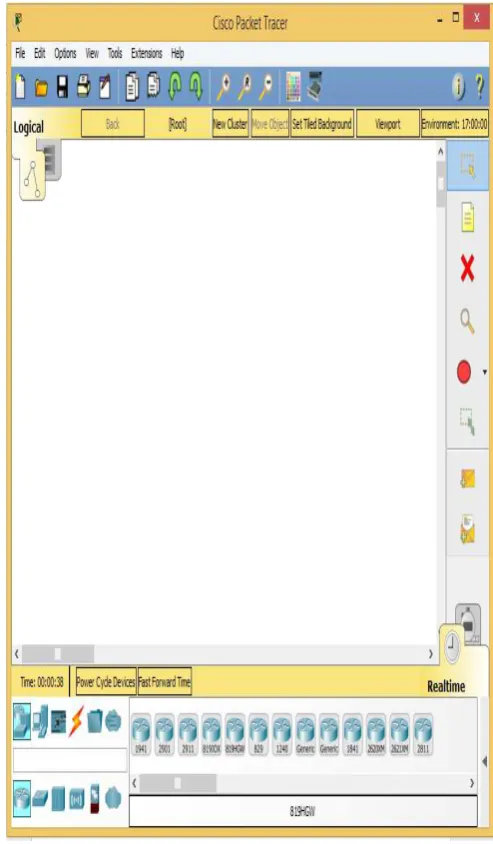
In order to design campus network I used cisco packet tracer .Cisco Packet Tracer is a networking simulator used for teaching and learning program by offering a unique combination of realistic[7][8].
Benefits of Packet Tracer are:
•
Offers a realistic simulation and visualization•
Permits users to design, build, configure, and troubleshoot complex networks• Allows students to explore concepts, conduct experiments,
Currently released cisco packet tracer included new feature like new device, sensor, and
Programming Languages with classically
networking device, those device stated below [4].
Things and Components available in Packet Tracer 7.0
• Smart Things are smart object attached to the Registration Server or Home Gateway through a network interface. They are divided into 4 subcategories: Smart City, Home, Industrial, and Power Grid.
• Components are smart objects that link to microcontroller (MCU-PT) or single boarded computers (SBC-PT). Not have a network interface and rely on the MCU-PT or SBC-PT for network access. This smart object can communicate through analog or digital slots.
A. New Future of Cisco Packet Tracer 7.0
• Registration server for IoT devices
• IOE devices and sensors in a new IoE devices category: solar panel, power meter, car, wireless home gateway, power meter, motion detector, temperature sensor, conveyor sensor,
• Programming languages for IoE. • Single board Computer (SBC) • Microcontroller Unit (MCU • Wireless IOE RFID sensor. • Wireless IOE RFID items.
Fig. 2: Four Categories of Smart Thing
Each category has their own smart thing that is applicable in categories. Example: in home categories different smart things are there such as smart door, co detector, co2 detector, humidifier, home speaker, motion detector, humidity monitor, smoke detector, siren, webcam and smart window.
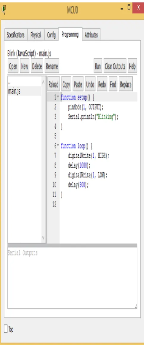
Fig. 3: MCU and SBC Microcontroller
This microcontroller provide programming environment (fig. 3) in order to control the smart things connected to this two boards.
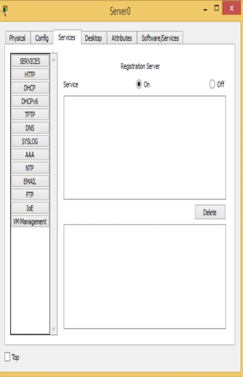
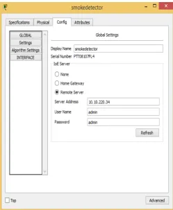
Fig. 5: IOE Registration Server
Smart things can directly register to IOE Serverora Home Gateway configured with the IoE service. Home Gateway have 4 Ethernet ports in addition to a wireless access point configured with the "Home Gateway" SSID.To secure wireless connection WEP / WPA-PSK / WPA2 enterprise can be configured on home gateway. The figure below shows four internet of Things device connected to a Home Gateway by using Ethernet cable and wireless. To connect the Home Gateway to the Internet its Internet WAN Ethernet port available on home getaway.
Fig. 6: Home Gateway with Four Smart Things Connected To Home Gateway
IV. IMPLEMENTATION
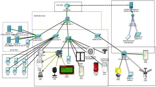
Fig. 7: Proposed Architecture
A. Device Used for Design
No Device Function
1 Router(1941) Used to connect campus network to the internet 2 layer two
switch (2960)
Used to distribute access to the lower layer
3 Layer three switch(3560)
Used to perform intra VLAN routing
4 Server To control smart thing registered on it and provide difference server functionalities
5 Central office server
Used to connect cellular system to the router
6 MCU Used to interconnect different smart thing 7 Pc Connect to access layer 8 Fan Used to ventilate the
campus based on some condition
9 Webcam Control the campus
10 Siren Provide sound for some event in the campus
11 Light Provide light 12 Motion
detector
Connect to home getaway and provide
Detection of motion
13 Smart door Connect to home getaway and provide
Function based event
14
Cell tower Provide cellular system coverage for different user
15 Tablet Used to control the campus from outside
16 Old car To detect smoke
17 LCD To display text
18 Motion sensor
To sense motion by mouse movement
B. Device Configuration
To implement the campus network design on cisco packer tracer , I used class A IP address that is 10.10.220.0/24 subnet and this subnet divided
corerouter(config-if)#ip address 10.10.220.1 255.255.255.224
corerouter(config-if)#no shutdown
corerouter(config)#int g0/1
corerouter(config-if)#ip add 209.165.20.225
255.255.255.224
corerouter(config-if)#no sh
corerouter(config)#ipdhcp excluded-address 209.165.20.225 209.165.20.229
corerouter(config)#ipdhcp pool tell
corerouter(dhcp-config)#network 209.165.20.224 255.255.255.224
corerouter(dhcp-config)#default-router 209.165.20.225
corerouter(dhcp-config)#dns-server 10.10.220.40
Command for checking running configuration
corerouter#show running-config Building configuration...
Current configuration : 1072 bytes !
version 15.1
no service timestamps log datetimemsec no service timestamps debug datetimemsec service password-encryption
!
hostname corerouter !
enable secret 5
$1$mERr$Me19uJMtOy6/CjrWm.7sd1 !
ipdhcp excluded-address 209.165.20.225 209.165.20.229
!
ipdhcp pool tell
network 209.165.20.224 255.255.255.224
default-router 209.165.20.225
license udipid CISCO1941/K9 sn FTX1524UANM
!
spanning-tree mode pvst !
interface GigabitEthernet0/0
ip address 10.10.220.1 255.255.255.224 duplex auto
speed auto !
interface GigabitEthernet0/1
ip address 209.165.20.225 255.255.255.224 duplex auto
ip route 10.10.220.0 255.255.255.0 10.10.220.2 ip route 10.10.220.0 255.255.255.224 10.10.220.2 !
ip flow-export version 9 !
no cdp run !
!
line con 0
password 7 08224D43190C16 !
line aux 0 !
line vty 0 4
password 7 08224D43190C16 login
line vty 5 15
password 7 08224D43190C16 login
• Distribution Layer Device address 10.10.220.96 10.10.220.99
multlayerswitch3(config)#ipdhcp pool address 10.10.220.128 10.10.220.130 multlayerswitch3(config)#ipdhcp pool
Current configuration : 2742 bytes !
version 12.2
no service timestamps log datetimemsec no service timestamps debug datetimemsec no service password-encryption
!
hostname multlayerswitch !
ipdhcp excluded-address 10.10.220.64 10.10.220.68
ipdhcp excluded-address 10.10.220.96 10.10.220.100
ipdhcp excluded-address 10.10.220.128 10.10.220.130
ipdhcp excluded-address 10.10.220.33 10.10.220.35
!
ipdhcp pool serverroom
network 10.10.220.32 255.255.255.224 default-router 10.10.220.33
dns-server 10.10.220.35 ipdhcp pool admin
network 10.10.220.64 255.255.255.224 default-router 10.10.220.65
dns-server 10.10.220.35 ipdhcp pool mcusmartthing
network 10.10.220.96 255.255.255.224 default-router 10.10.220.97
dns-server 10.10.220.35 ipdhcp pool getwaysmartthing
network 10.10.220.128 255.255.255.224 default-router 10.10.220.129
spanning-tree mode pvst
interface FastEthernet0/1 switchport access vlan 10 switchport mode access !
!
interface FastEthernet0/3 switchport access vlan 30 switchport mode access !
interface FastEthernet0/4 switchport access vlan 20 switchport mode access !
ip address 10.10.220.33 255.255.255.224 !
mac-address 00e0.f9c0.0002
ip address 10.10.220.65 255.255.255.224 !
interface Vlan30
mac-address 00e0.f9c0.0003
ip address 10.10.220.97 255.255.255.224 !
interface Vlan40
mac-address 00e0.f9c0.0004
ip address 10.10.220.129 255.255.255.224 !
ip classless
ip route 209.165.20.224 255.255.255.224 10.10.220.1
!
ip flow-export version 9 !
no cdp run !
line con 0 !
line aux 0 !
line vty 0 4 login ! ! ! end
C. Device Setup
After configuration is done the device get IP address dynamically and IOE device registered to IOE server or home getaway.
Fig. 8: Pc Gets IP Address Dynamically
Fig. 9: IOE Device Get IP Address Dynamically
The above Fig shows Registering IOE device to IOE server to control IOE device form remote or local by legitimate person that have username and password.
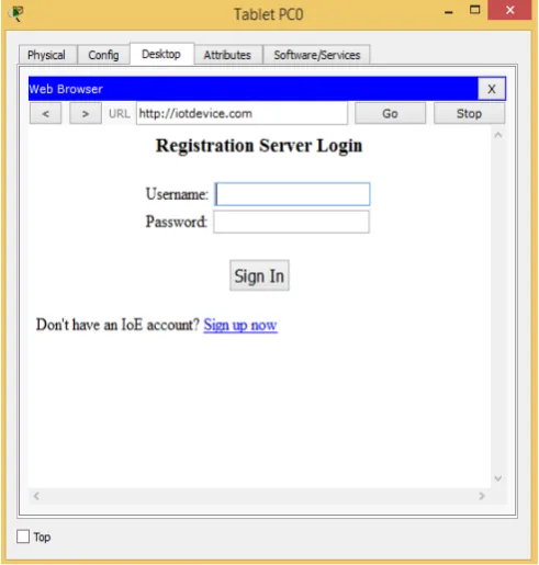
Fig. 11: Login page for IOT Register Server
Legitimate user can log the system from remote or local to control smart thing registered on the system.
Fig. 12: Controlling Smart Thing Form Local
Above fig shows Controlling ceiling fan by making off/low/high and also control light by making on/dim/off.
Fig.13: Controlling Smart Thing Form Remote Network
Fig. 14: Condition Making For Smart Thing on Server
Fig.15: Shows Fire Sprinkler and Siren Are on
The above fig shows Fire sprinkler and siren are on when smoke level above 10 to ventilate the place and alarm the surrounding. To detect smoke old car was used. As old car has a lot of problem.
Microcontroller unit (MCU) is a board used to inter connect smart thing and sensor for controlling and provide programming environment to manage the things connected to it. The following python program are written on MCU to control and safe resource used by difference smart things.
from gpio import * from time import *
def main():
pinMode(0, OUT) pinMode(1, OUT) pinMode(2, OUT) pinMode(3, IN)
pinMode(4, OUT) print("BLINKING") while True:
customWrite(1, "wel come"); digitalWrite(2, LOW); customWrite(0, 0); customWrite(4, 0); if (digitalRead(3)):
customWrite(3, 0); customWrite(0, 1); customWrite(1, "Warning");
digitalWrite(2, HIGH); customWrite(4, 1); print("ALERT")
delay(1000)
Fig.16: Shows MCU Control the Smart Thing and Sensor Connected To It.
The above Fig shows if motion is detected in case of security the siren, alarm, webcam are on and LCD display warning text. To control this events the above python program implemented on central MCU.
V. CONCLUSION
To improve the campus network service, this paper proposed Smart Campus NetworkDesign (SCND) by assimilating internet of thing device with classically network device.Each smart device registered to IOT server or home getaway and controlled by legitimate user.This design also include Hierarchical Network Design as a hierarchical design is used to group devices into multiple layers. This paper also present about Microcontroller unit (MCU) that used to interconnect different IOE device and control them by coding.To design the proposed campus network design I used cisco packet tracer simulator software.
REFERENCE
[1].S. Haller S. Karnouskos and C. Schroth "The Internet of Things in an Enterprise Context " in Future Internet-FIS 2008 Lecture Notes in Computer Science Vol. 5468 2009 pp 14-28. [2].A. C. Sarma and J. Girão "Identities in the
Future Internet of Things” in Wireless Personal Communications 49.3 2009 pp. 353-363.
[3].Roberto Minerva AbiyBiru "Towards a Definition of the Internet of Things” IEEE IoT Initiative white paper.
[4]. http://www.packettracernetwork.com/internet-of-things/pt7-iot-devices-configuration.html.
[5].Current, John R., Charles S. ReVelle, and
Jared L. Cohon. "The hierarchical network
design problem." European Journal of
Operational Research 27.1 (1986): 57-66.
[6].Qin, X. U. E. "Simulation Experimental
Packet Tracer [J]." Research and Exploration
in Laboratory 2 (2010): 57-59.
[7].Sun, L., Wu, J., Zhang, Y., & Yin, H. (2013, April). Comparison between physical devices and simulator software for Cisco network technology teaching. In Computer Science & Education (ICCSE), 2013 8th International Conference on (pp. 1357-1360). IEEE.
[8].Qin, X. U. E. "Simulation Experimental