MODEL SIMULATION OF GEOMETRY AND STRESS-STRAIN
VARIATION OF BATAN FUEL PIN PROTOTYPE DURING
IRRADIATION TEST IN RSG-GAS REACTOR*)
Suwardi1), W. Dewayatna1), Sungkono1), Ridwan1), M. Rifai2) 1)Center for Nuclear Fuel Technology – BATAN
2)Center for Advanced Material - BATAN
Kawasan Puspiptek, Serpong, Tangerang Selatan, 15314 e-mail: [email protected]
(Naskah diterima : 8-12-2014, Naskah direvisi: 22-01-2015, Naskah disetujui: 23-01-2015)
ABSTRACT
MODEL SIMULATION OF GEOMETRY AND STRESS-STRAIN VARIATION OF BATAN FUEL PIN PROTOTYPE DURING IRRADIATION TEST IN RSG-GAS REACTOR*). The first short fuel pin containing natural UO2 pellet in Zry4 cladding has been prepared at the CNFT (Center for Nuclear Fuel Technology) then a ramp test will be performed. The present work is part of designing first irradiation experiments in the PRTF (Power Ramp Test Facility) of RSG-GAS 30 MW reactor. The thermal mechanic of the pin during irradiation has simulated. The geometry variation of pellet and cladding is modeled by taking into account different phenomena such as thermal expansion, densification, swelling by fission product, thermal creep and radiation growth. The cladding variation is modeled by thermal expansion, thermal and irradiation creeps. The material properties are modeled by MATPRO and standard numerical parameter of TRANSURANUS code. Results of irradiation simulation with 9 kW/m LHR indicates that pellet-clad contacts onset from 0.090 mm initial gaps after 806 d, when pellet radius expansion attain 0.015 mm while inner cladding creep-down 0.075 mm. A newer computation data show that the maximum measured LHR of n-UO2 pin in the PRTF 12.4 kW/m. The next simulation will be done with a higher LHR, up to ~ 25 kW/m.
Kata kunci: irradiation, fuel pin, natural UO2, geometry, stress-strain.
ABSTRAK
MODEL SIMULASI VARIASI GEOMETRI DAN STRESS-STRAIN DARI PROTOTIP BAHAN BAKAR PIN BATAN SELAMA UJI IRADIASI DI REAKTOR RSG-GAS. Pusat Teknologi Bahan Bakar Nuklir (PTBBN) telah menyiapkan tangkai (pin) bahan bakar pendek perdana yang berisi pelet UO2 alam dalam kelongsong paduan zircaloy untuk dilakukan uji iradiasi daya naik. Penelitian
ini merupakan bagian dari perancangan percobaan iradiasi pertama di PRTF (Power Ramp Test
Fasility) yang terpasang di reaktor serbaguna RSG-GAS berdaya 30 MW. Telah dilakukan pemodelan dan simulasi kinerja termal mekanikal pin selama iradiasi. Variasi geometri pelet dan kelongsong selama pengujian dimodelkan dengan memperhatikan fenomena ekspansi termal, densifikasi, bengkak oleh produk fisi, creep termal dan pertumbuhan iradiatif. Variasi sifat kelongsong dimodelkan oleh ekspansi termal, termal dan creep iradiatif. Sifat material dimodelkan dengan MATPRO serta parameter numerik standar kode TRANSURANUS. Hasil iradiasi simulasi dengan laju daya 9 kW/m, 75% data daya aksimal, menunjukkan bahwa awal kontak fisik pelet dengan kelongsong dari celah awal 0,09 mm terjadi setelah 806 hari, ketika ekspansi jejari pelet mencapai 0,015 mm sementara jejari kelongsong menyusut 0,075 mm. Data terbaru menunjukkan bahwa perhitungan maksimal dan pengukuran laju daya linear tangkai bahan bakar berisi UO2 alam
Keywords:
iradiasi, pin bahan bakar, UO
2alam, geometri, tegangan-regangan.
*) The paper has been presented in The 23rd International Conference on Nuclear Engineering, May 17-21, 2015, Chiba, Japan with paper ID is ICONE23-1946
INTRODUCTION
During the early decades of the 80,
The “Gamma” Research Center of Batan in Yogyakarta started doing R & D in production of heavy water as coolant and moderator with D2O pilot plant facilities. There was also started a purification process and the manufacture of UO2 from yellowcake. Preliminary design of the yellowcake plant as a by-product phosphoric acid plant and
fertilizer Chemical Petrolium “Gresik” PT PKG has been done by the author and supervised by Supranto in 1983 at Gadjah Mada University of Chemical Engineering Department [1]. A few years later, PT PKG has founded the factory and operate a pilot plant yellow-cake as a byproduct of phosphoric acid units. Examples of the results of the pilot plant yellowcake had been sent to BATAN (National Nuclear Energy Agency) Facility at Serpong (PPTA-S). PPTA-S consist of research facility for the nuclear industry, including nuclear fuel technology, including installation of the Experimental Fuel Elements Installation (EFEI) equipped with a PCP (Pilot plant conversion) yellowcake into UO2. The experimental fuel technology is based on HWR fuel bundle type CIRENE (CISE Reator a Nebule - mist-cooled Reactor) developed by CISE (Suwardi, 2013). The Fuel Element Production Installation (FEPI). The RSG-GAS 30 MW multipurpose reactor functionality is for irradiation testing of developed fuel, and the Radio-Metallurgy Installation (RMI) for performing an examination of irradiated nuclear fuel and material. Lastly the Radioactive Waste Installation (RWI) serves for managing different kind of radioactive waste.
The purpose of this study analyzes the performance gain when tested in prototype pin PRTF as a support document
for permission to perform the irradiation experiment. The minimum time of irradiation up onset PCMI is a minimum to be determined.
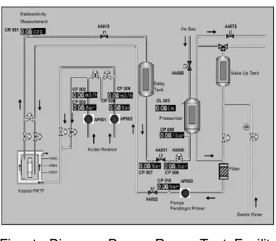
Fig. 1. Diagram Power Ramp Test Facility installed in RSG-GAS 30 MW multi purpose reactor (H.Sudirdjo, 2008)
It is related to fission gas released into the gap and the plenum, and effective stress strain transversal indicator probability that a failed cladding by SCC enhanced phenomenon (Van-Uffelen, 2011 and Schubert, 2011).
Fig. 2. Shop drawing of PRTF capsule. (Sudirdjo, 2008)
METODOLOGI
geometry test fuel pins presented in Table 1 allows the calculation of pin parameters. Volume fraction and absolute volume, volume gap pellets - at initial state.
Table 1. Principal data on fuel pin prototype prepared in EFEI (Sulistyono, 2014)
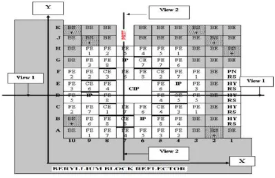
Fuel Pin Parameter Value Unit Pellet: and J7 located at the core periphery of RSG-GAS, as presented in the layout of Fig.3.The notation of the figure is FE: fuel element, CE:
control element, BE: Be reflector element, BS+: Be reflector element with plug, IP:
irradiation position, CIP: central irradiation position, PNRS: pneumatic rabbit system, HYRS: hydraulic rabbit system)
The studied irradiation test consists of flat linear heat rate followed by decreasing up to the end of burn up about 6000 MWd/kg. Fig. 4 shows the history of generated heat, neutron flux and obtained fuel burn up.
Fig. 3. Layout of RSG-GAS core where the PRTF located at core periphery. (Hong, 2010)
The calculation of the parameters for a pin during simulation has been done with modeling component properties and phenomena and taken into account the changes in the pellet such as temperature, thermal expansion, cracked pellet densification, restructuring, swelling by solid fission products and gas, gas dynamics, and three-dimensional stress strain of pellets and mechanical behavior of cladding such as thermal expansion, thermal creep, irradiation induced growth and relaxation. The boundary condition of calculattion was PRTF data and irradiation scenario. These phenomena has been simulated by an axial symmetry calculation method using the Transuranus code originated by Lasman (Schubert, 2008). The code has been verified for the phenomenon in many papers and partly collected in Handbook of Transuranus (Anonym, 2011).
As schematically shown in Fig.1 and 2, the fuel pin is located in side high temperature and pressure of PRTF which is in turn cooled by forcing turbulent flowing coolant within vertical annulus at 1200 l/hour at water pool temperature and pressure pumped by AP001 and/or AP002. The typical cooling water / moderator of pool RSG-GAS is at atmospheric and temperature ~35°C. The simulated temperature and pressure of test fuel inside the PRTF capsule has been 250oC and 150 atm.
calculation method using the Transuranus code originated by Lassman (Schubert, 2008). The code has been verified for the phenomenon in many papers and partly collected in Handbook of Transuranus (Anonym, 2011).
Fig. 4. Irradiation history of average burn-up during irradiation of fuel pin
The PRTF position in the reactor core is at periphery as shown in Fig. 3. The mining of figure notations is FE: fuel element, CE:
control element, BE: Be reflector element, BS+: Be reflector element with plug, IP:
irradiation position, CIP: central irradiation position, PNRS: pneumatic rabbit system, HYRS: hydraulic rabbit system.
For material properties, in case no measured material property for input the simulation, the standard properties from MATPRO and other property standard of Transuranus version M1v1J12 have been applied.
The most important input and output calculation according to the onset time for PCMI presented for discussion: the average linear heat rate history, the radial distribution of temperature at various irradiation times, the accumulated average burn up pellet radial burn up distribution and gas fission produced and released, the history of the movement and changes the geometry of pin: pellets, cladding and the size of the gap. Some of pertinent obtained data is presented for discussion.
RESULT AND DISCUSSION
In fuel performance modeling codes, the conductivity model is applied locally along
the radial burn up profile. Effect of fuel
thermal conductivity degradation on centerline temperature is manifested in the constant centerline temperature increase with burn up as illustrated in Figure 4. One may note that the centerline temperature increase (the difference between “fresh” and
irradiated fuel) is more than 30 oC even though highly non-uniform of power profile.
Fission gas. Fig. 6 shows the corresponding distribution of fission gas produced and released of the 4th curve of Fig.4.
Nuclide production of fission products in the solid phase and gas phase volatile cause swelling pellets. Fission gas is the most important for pellet swelling due to gas bubbles grain settles as intra- and inter-after saturation of the solid solution. When the pellet temperature exceeds some threshold for fission gas release regardless > 1% for open pores, crevices, and plenum.
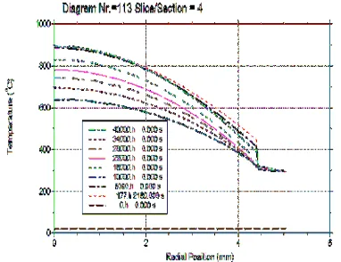
Fig. 5. Radial distribution of pin temperature at different irradiation time.
increased significantly, although at pellet surface the temperature decreased, which is corresponding to further closure of the fuel-pellet gap.
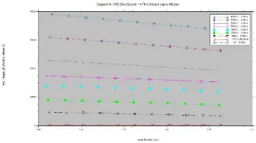
Fig.6. Radial distribution of produced and released fission gas along position at 20000 hour
Because the temperature of the release pellets below the threshold, the gases released are very small compared to the total generated, as shown in Figure 4. If the cladding stress is sufficiently large, and the pellet temperature high enough to release corrosive fission products, internal cracks can be initiated into the inner bore with stress corrosion cracking (SCC) that grows under the influence of hoop stress is maintained so that the cladding fails. However, even on the outside of the pellet highest fission gas production, regarding to the highest local burn up, but the total fission gas irrespective below 1%, not a potential cause SCC-Enhanced.
Fig. 7. Evolution of gap size for different slice of fuel pin.
Pellet-cladding gap. In Fig.7, the gap or distance between the surface and the surface of the pellet cladding in shrink, eventually closed (onset PCMI, Interaction Mechanical Pellet - Cladding). Before closing
the gap, the cladding is under stress by water coolant system pressure. Once the gap is closed and the cladding and pellet fragments are in contact, circular voltage gradually decreases as the pellet fragments reject cladding diameter reduction. The cladding hoop stress becomes eventually positive when all the internal free space exhaustion and pellet fragments are in intimate contact.
The increase in power that occurred during PCMI conditions, i.e., after the irradiation time, even though the base load to reach the onset , increases the failure probability caused by pellet cladding mechanical and chemical interaction, which has not evaluated.
Fig. 8. Diameter change of clad and pellet of slice-3 during irradiation
At temperatures of 250oC cladding down by creep into (creep-down) voltage negative circular hoop. caused by the difference between the refrigerant pressure and the internal pressure of the fuel rods.
Fig. 9. (a) Radial distributions of cladding effective strees at different irradiation time.
cladding presented at Fig.8. Bottom curve is pellet radius, rose slowly due to swelling by solid fission products and gas. Relatively low temperatures does not produce a high swelling.
Fig.10. Radial distributions of different radial, tangential, axial and equivalent stress state of cladding at 20 000 h of irradiation.
The evolution of pin diameter is shown in Fig.8 where the red curve in middle position is the internal radius of cladding, and the black top curve is the outer radius of cladding and the blue of lowest curve is pellet radius. It is shown that the outer radius so its diameter of cladding is consistently going down, also the inner radius of cladding, but began stopping at about 17000 hours when it met the outer surface of the pellet. Shrinkage of cladding associated external pressure much higher than inside the fuel cladding. The cladding diameter declines slowly up to pellet cladding mechanical contact. The strength of pellet is much higher than cladding and further mechanical contact may produce upward creep of cladding.
Fig.11. Evolution of average cladding strain of slice-4 during irradiation test.
Stress-strain cladding irradiation state before PCI tests and related to the dependent and independent parameters of given fuel data pins is presented in Fig.9 to Fig.11. The predictions will be used as a guide for PIE sampling and examination. Base on computation results, that the radial and tangential stresses to the cladding are limited, the ramp test will give no potential to cladding failure. Firstly the stress strain caused by pellet swelling is very limited, secondly there is no (~ zero) released fission gas, no corrosive gas enter to pellet-gap nor inner surface of cladding. The absence of two dominant parameter of phenomenon stress corrosion cracking, resulted no potential of failure caused by power ramp. Recent numerical studies can be used to design optimization and design of both experimental fuel rods. A good PIE data can be used as benchmarking for obtained modeling simulation.
Fig.12. Axial distribution of calculated heat flux along pin fuel inside PRTF capsule (Susilo, 2015)
A new axial distribution of neutron flux and a corresponding thermal for fresh natural UO2 fuel pin of K-7 and J-7 position has been obtained (Susilo, 2015). It was calculated when Reactor power is 15 MW. The average neutron flux at K-7 and J-7 published earlier was 0.4E+10 thermal n/cm2/s (Arbi, 1987) is the same order to
Susilo’s value [11].
cited earlier. The average data from fluence measurement is about 200 times to the calculated one (1.2E+14) thermal n/cm/s at 30 MW reactor power (Taryo, 2014). This ratio of neutron flux at PRTF location is about the value of the ratio of reactor power. Table 2. PRTF neutrons flux, different fuels.
(Taryo, 2014). twice greater than observed in operational test of PRTF. The recent data are corresponding to full power (30 MW) of RSG-GAS design (Taryo, 2014). The authors assume that the obtained measurement data has been done when the reactor was operated at the half of designed power.
The base of these higher measured and computed data of thermal neutron flux, a heat rating of 70 kW/m can be performed for enriched Uranium fuel, and for load follow for natural uranium fuel. Replacement of pin light water bath with heavy water need to be studied for probability to power ramp test of surrogated PWR pin containing natural UO2.
CONCLUSION
CNFT has prepared a short pin as fuel pin prototype based on natural UO2 pellet, as a surrogate of PWR fuel, then will perform irradiation tests in the PRTF. A simulation of the irradiation test has been performed for predicting diameter change both pellet and cladding and to determine eventually the onset of pellet-cladding contact.
The simulation has been based on input information from fuel manufacturer, material properties measured or modeled.
The initial pellets - for clad gap of 0.1 mm with a model of material properties, parameter choice and irradiation test scenarios, for efficiency of experimentation.
In connection with the power to test fuel pins and the scenarios analyzed by the chosen model, it was found that PCMI occurred at about 17000 hours or 708.333 days. It is about the end of the commercial irradiated PHWR fuel with only natural uranium. This is considered as the minimum irradiation time needed to evaluate power and including ramp energy.
The calculated thermal flux in the first way is significantly lower than published
work. The author’s preference for further experiment should be includes re-evaluation of PRTF device.
ACKNOWLEDGMENTS
The authors want to thank to Mr. Basak the Coordinator of IAEA CRP-1127 who made the author realize their research plan and also to their partners of Institute of Transuranium Element - Joint Research Centre of European Commission for licensing of the TransUranus code used in this work. The authors would address acknowledgment to Mr. J. Susilo Mr. J. Iman and Mr, W. Dewayatna from BATAN for supporting neutronic data.
REFERENCES
[1] Suwardi, 2013, Parametric Study on irradiation test of CNFT fuel prototype, Proc. WWER Fuel Performance Modeling and Experiment Support, Sandanski Bulgaria, 2013
[2] Anonym, 1983, Manufacturing CIRENE fuel by ENEA, Comb. IEEC, Nuclear Fuel Manufacturing Division, ITALY. [3] H.Sudirdjo et al. 2005, Revitalization of
[4] Anonym, 2011, Transuranus Handbook, European Commission, Joint Research Centre-JRC, ITU 2011.
[5] P. VAN UFFELEN and M. SUZUKI, 2011, Chapter 71 "Fuel Performance Modeling and Simulations: Oxide Fuel Performance Modeling and Simulation" in Comprehensive Nuclear Materials, edited by R. Konings, accepted for publication in J. Nucl. Mat., 2011. [6] A. SCHUBERT, P. VAN UFFELEN, J. van
de LAAR, C. T. WALKER, W. HAECK, 2008, Journal of Nuclear Materials,Vol. 376 (2008) 1-10.
[7] P. VAN UFFELEN, Cs. GYÖRI, A. SCHUBERT, J. van de LAAR, Z. HÓZER, G. SPYKMAN, 2008, Journal of Nuclear Materials, Vol. 383 (2008) 137-143.
[8] T.Taryo and T.M. Sembiring, 2014, Analysis of Neutron Flux Distribution in RSG-GAS Reactor with U-Mo Fuels, Center for Development of Research Reactor Technology- BATAN, Tangerang, Indonesia, 2014.
[9] B.Arbie, 1987, Bakri ARBIE and Sutaryo SUPADI, Status Report on the Indonesian Multipurpose Reactor RSG-GAS, BATAN, Indonesia, 1987.
[10] J. Iman, 2015, privat communication, RSG-GAS, Serpong, Indonesia.
[11] J. Susilo, 2015, privat communication, Center for Nuclear Technology and Reactor Safety Serpong, Indonesia. [12] L.P. Hong and T.M. Sembiring, Nuclear
Engineering and Design 240 (2010)1433-1442.