Wireless Networking in
the Developing World
Second Edition
Wireless Networking in the Developing World
For more information about this project, visit us online at http://wndw.net/First edition, January 2006 Second edition, December 2007
Many designations used by manufacturers and vendors to distinguish their products are claimed as trademarks. Where those designations appear in this book, and the authors were aware of a trademark claim, the designations have been printed in all caps or initial caps. All other trademarks are property of their respective owners.
The authors and publisher have taken due care in preparation of this book, but make no expressed or implied warranty of any kind and assume no responsibility for errors or omissions. No liability is assumed for incidental or consequential damages in connection with or arising out of the use of the information contained herein.
© 2007 Hacker Friendly LLC, http://hackerfriendly.com/
Contents
Where to Begin
1
...
Purpose of this book 2
...
Fitting wireless into your existing network 3
...
Wireless networking protocols 3
...
Question & Answer 5
A Practical Introduction to Radio Physics
9
...
Behavior of radio waves 15
...
Line of sight 22
... Power 24
...
Physics in the real world 26
Network Design
27
...
Designing the physical network 51
...
802.11 wireless networks 54
...
Mesh networking with OLSR 56
...
Estimating capacity 65
...
Traffic optimization 79
...
Internet link optimization 89
...
More information 93
Antennas & Transmission Lines
95
...
Antennas & radiation patterns 102
Networking Hardware
135
Commercial vs. DIY solutions 139
...
Building an access point from a PC 143
Security & Monitoring
157
...
Physical security 158
...
Threats to the network 160
...
The power charge regulator 229
... Converters 231
...
Equipment or load 232
...
How to size your photovoltaic system 238
...
Cost of a solar installation 246
Building an Outdoor Node
249
...
Aligning antennas on a long distance link 258
...
Surge and lightning protection 263
...
Create a Mission Statement 282
...
Evaluate the Demand for Potential Offerings 283
...
Establish Appropriate Incentives 284
... Research the Regulatory Environment for Wireless 286
...
Analyze the Competition 286
... Determine Initial and Recurring Costs and Pricing 287
...
Secure the Financing 291
... Evaluate the Strengths and Weaknesses of the Internal Situation 293
...
Putting it All Together 294
... Case study: Crossing the divide with a simple bridge in Timbuktu 302
...
Case study: Finding solid ground in Gao 305
... Case Study: Fantsuam Foundation's Community Wireless Network 308
... Case study: The quest for affordable Internet in rural Mali 319
... Case study: Commercial deployments in East Africa 325
... Case study: Dharamsala Community Wireless Mesh Network 332
...
Case study: Networking Mérida State 334
...
Case study: Chilesincables.org 345
...
Case study: Long Distance 802.11 355
Appendix A: Resources
371
Appendix B: Channel Allocations
379
Appendix C: Path Loss
381
Appendix D: Cable Sizes
382
About This Book
This book is part of a set of related materials about the same topic: Wireless Networking in the Developing World. The WNDW project includes:
• Printed books, available on demand
• Several translations, including French, Spanish, Portuguese, Italian, Arabic, and others
• A DRM-free PDF and HTML version of the book
• An archived mailing list for discussion of the concepts and techniques described in the book
• Additional case studies, training course material, and related information
For all of this material and more, see our website at http://wndw.net/
The book and PDF file are published under a Creative Commons Attribution-ShareAlike 3.0 license. This allows anyone to make copies, and even sell them for a profit, as long as proper attribution is given to the authors and any deriva-tive works are made available under the same terms. Any copies or derivaderiva-tive works must include a prominent link to our website, http://wndw.net/.
Seehttp://creativecommons.org/licenses/by-sa/3.0/ for more information about these terms. Printed copies may be ordered from Lulu.com, a print-on-demand service. Consult the website (http://wndw.net/) for details on ordering a printed copy. The PDF will be updated periodically, and ordering from the print-on-demand service ensures that you will always receive the latest revision.
The website will include additional case studies, currently available equip-ment, and more external website references. Volunteers and ideas are wel-come. Please join the mailing list and send ideas.
The training course material was written for courses given by the Associa-tion for Progressive CommunicaAssocia-tions and the Abdus Salam InternaAssocia-tional Center for Theoretical Physics. See http://www.apc.org/wireless/ and
This book was started as the BookSprint project at the 2005 session of WSFII, in London, England (http://www.wsfii.org/). A core team of seven people built the initial outline over the course of the event, presented the results at the conference, and wrote the book over the course of a few months. Throughout the project, the core group has actively solicited con-tributions and feedback from the wireless networking community. Add your own feedback and updates to the WNDW wiki at http://wiki.wndw.net/. • Rob Flickenger was the lead author and editor of this book. Rob has written
and edited several books about wireless networking and Linux, including
Wireless Hacks (OReilly Media) and How To Accelerate Your Internet
(http://bwmo.net/). He is proud to be a hacker, amateur mad scientist, and proponent of free networks everywhere.
• Corinna “Elektra” Aichele. Elektras main interests include autonomous power systems and wireless communication (antennas, wireless long shots, mesh networking). She made a small linux distro based on slack-ware geared to wireless mesh networking. This information is of course redundant if one reads the book... http://www.scii.nl/~elektra
• Sebastian Büttrich (http://wire.less.dk/) is a generalist in technology with a background in scientific programming and physics. Originally from
Ber-lin, Germany, he worked with IconMedialab in Copenhagen from 1997 until 2002. He holds a Ph.D. in quantum physics from the Technical University of Berlin. His physics background includes fields like RF and microwave
spectroscopy, photovoltaic systems, and advanced maths.
He is also a performing and recording musician.
• Laura M. Drewett is a Co-Founder of Adapted Consulting Inc., a social en-terprise that specializes in adapting technology and business solutions for the developing world. Since Laura first lived in Mali in the 1990s and wrote her thesis on girls education programs, she has strived to find sustainable solutions for development. An expert in sustainability for ICT projects in de-veloping world environments, she has designed and managed projects for a diversity of clients in Africa, the Middle East and Eastern Europe. Laura holds a Bachelors of Arts with Distinction in Foreign Affairs and French from the University of Virginia and a Masters Certificate in Project Management from the George Washington University School of Business.
countries and released over 600 pages of documentation under Creative Commons License. More information can be found at http://www.it46.se/
• Carlo Fonda is a member of the Radio Communications Unit at the Abdus Salam International Center for Theoretical Physics in Trieste, Italy.
• Jim Forster has spent his career in software development, mostly work-ing on operatwork-ing systems and networkwork-ing in product companies. He has experience with several failed startup companies in Silicon Valley, and one successful one, Cisco Systems. After a lot of product development work there, his more recent activities involve projects and policies for im-proving Internet access in developing countries. He can be reached at
• Ian Howard. After flying around the world for seven years as a paratrooper in the Canadian military, Ian Howard decided to trade his gun for a computer.
After finishing a degree in environmental sciences at the University of
Wa-terloo he wrote in a proposal, "Wireless technology has the opportunity to bridge the digital divide. Poor nations, who do not have the infrastructure for interconnectivity as we do, will now be able to create a wireless infra-structure." As a reward, Geekcorps sent him to Mali as the Geekcorps Mali Program Manager, where he led a team equipping radio stations with wire-less interconnections and designed content sharing systems.
He is now a consultant on various Geekcorps programs.
• Kyle Johnston, http://www.schoolnet.na/
• Tomas Krag spends his days working with wire.less.dk, a registered non-profit, based in Copenhagen, which he founded with his friend and
col-league Sebastian Büttrich in early 2002. wire.less.dk specialises in com-munity wireless networking solutions, and has a special focus on low-cost wireless networks for the developing world.
Tomas is also an associate of the Tactical Technology Collective
http://www.tacticaltech.org/, an Amsterdam-based non-profit “to
strengthen social technology movements and networks in developing and transition countries, as well as promote civil societys effective, conscious and creative use of new technologies.” Currently most of his energy goes into the Wireless Roadshow (http://www.thewirelessroadshow.org/), a pro-ject that supports civil society partners in the developing world in planning, building and sustaining connectivity solutions based on license-exempt spectrum, open technology and open knowledge.
wireless data services in Tanzania, Messer worked for 11 years in eastern and southern Africa in voice and data communications for startups and multinational cellular carriers. He now resides in Amman, Jordan.
• Juergen Neumann (http://www.ergomedia.de/) started working with in-formation technology in 1984 and since then has been looking for ways to deploy ICT in useful ways for organizations and society. As a consultant for ICT strategy and implementation, he has worked for major German and international companies and many non-profit projects. In 2002 he
co-founded www.freifunk.net, a campaign for spreading knowledge and social networking about free and open networks. Freifunk is globally regarded as one of the most successful community-projects in this field.
• Ermanno Pietrosemoli has been involved in planning and building com-puter networks for the last twenty years. As president of the Latin American Networking School, Escuela Latinoamericana de Redes “EsLaRed”,
www.eslared.org.ve, he has been teaching wireless data communications in several countries while keeping his base at Mérida, Venezuela.
• Frédéric Renet is a co-founder of Technical Solutions at Adapted Consulting, Inc. Frédéric has been involved in ICT for more than 10 years and has worked with computers since his childhood. He began his ICT career in the early 1990s with a bulletin board system (BBS) on an analog modem and has since continued to create systems that enhance communication. Most recently, Frédéric spent more than a year at IESC/Geekcorps Mali as a consultant. In this capacity, he designed many innovative solutions for FM radio broadcast-ing, school computer labs and lighting systems for rural communities.
• Marco Zennaro, aka marcusgennaroz, is an electronic engineer working at the ICTP in Trieste, Italy. He has been using BBSes and ham radios since he was a teenager, and he is happy to have merged the two together work-ing in the field of wireless networking. He still carries his Apple Newton.
Support
• Lisa Chan (http://www.cowinanorange.com/) was the lead copy editor. • Casey Halverson (http://seattlewireless.net/~casey/) provided technical
review and suggestions.
• Jessie Heaven Lotz (http://jessieheavenlotz.com/) provided several updated illustrations for this edition.
• Richard Lotz (http://greenbits.net/~rlotz/) provided technical review and suggestions. He works on SeattleWireless projects and would like to take his node (and his house) off the grid.
• Lara Sobel designed the cover for WNDW 2nd Edition. She is an artist currently living in Seattle, WA.
• Matt Westervelt (http://seattlewireless.net/~mattw/) provided technical re-view and copy edit support. Matt is the founder of SeattleWireless (http://seattlewireless.net/) and is an evangelist for FreeNetworks worldwide.
About the solar power guide
The source material for the Solar Power chapter was translated and developed by Alberto Escudero-Pascual. In 1998, the organization Engineering without Borders (Spanish Federation) published the first version
of a handbook titled "Manual de Energía Solar Fotovoltaica y Cooperación al Desarrollo". The handbook was written and published by members of the NGO and experts of the Institute of Energy Solar of the Polytechnical University of Madrid. By curiosities of life, none of the members of the editorial team kept the document in electronic format and more editions were never made. They have passed almost ten years from that very first edition
and this document is an effort to rescue and to extend the handbook.
As part of this rescue operation Alberto would like to thank the coordinators of the first original edition and his mentors in his years at University: Miguel
Ángel Eguido Aguilera, Mercedes Montero Bartolomé y Julio Amador. This new work is licensed under Creative Commons Attribution-ShareAlike 3.0. We hope that this material becomes a new departure point for new editions including new contributions by the community.
This second and extended edition of the solar power guide has received valuable input from Frédéric Renet and Louise Berthilson.
Special thanks
The core team would like to thank the organizers of WSFII for providing the space, support, and occasional bandwidth that served as the incubator for this project. We would especially like to thank community networkers everywhere, who devote so much of their time and energy towards fulfilling the promise of the global Internet. Without you, community networks could not exist.
1
Where to Begin
This book was created by a team of individuals who each, in their own field,
are actively participating in the ever-expanding Internet by pushing its reach farther than ever before. The massive popularity of wireless networking has caused equipment costs to continually plummet, while equipment capabilities continue to sharply increase. We believe that by taking advantage of this state of affairs, people can finally begin to have a stake in building their own
communications infrastructure. We hope to not only convince you that this is possible, but also show how we have done it, and to give you the information and tools you need to start a network project in your local community.
Wireless infrastructure can be built for very little cost compared to traditional wired alternatives. But building wireless networks is only partly about saving money. By providing people in your local community with cheaper and easier access to information, they will directly benefit from what the Internet has to
offer. The time and effort saved by having access to the global network of information translates into wealth on a local scale, as more work can be done in less time and with less effort.
Likewise, the network becomes all the more valuable as more people are connected to it. Communities connected to the Internet at high speed have a voice in a global marketplace, where transactions happen around the world at the speed of light. People all over the world are finding that Internet
ac-cess gives them a voice to discuss their problems, politics, and whatever else is important to their lives, in a way that the telephone and television sim-ply cannot compete with. What has until recently sounded like science fiction
is now becoming a reality, and that reality is being built on wireless networks.
But even without access to the Internet, wireless community networks have tremendous value. They allow people to collaborate on projects across wide distances. Voice communications, email, and other data can be exchanged for very little cost. By getting local people involved in the construction of the network, knowledge and trust are spread throughout the community, and people begin to understand the importance of having a share in their com-munications infrastructure. Ultimately, they realize that communication net-works are built to allow people to connect with each other.
In this book we will focus on wireless data networking technologies in the 802.11 family. While such a network can carry data, voice, and video (as well as traditional web and Internet traffic), the networks described in this
book are data networks. We specifically do not cover GSM, CDMA, or other
wireless voice technologies, since the cost of deploying these technologies is well beyond the reach of most community projects.
Purpose of this book
The overall goal of this book is to help you build affordable communication technology in your local community by making best use of whatever re-sources are available. Using inexpensive off-the-shelf equipment, you can build high speed data networks that connect remote areas together, provide broadband network access in areas that even dialup does not exist, and ulti-mately connect you and your neighbors to the global Internet. By using local sources for materials and fabricating parts yourself, you can build reliable network links with very little budget. And by working with your local commu-nity, you can build a telecommunications infrastructure that benefits everyone
who participates in it.
This book is not a guide to configuring a radio card in your laptop or choosing
consumer grade gear for your home network. The emphasis is on building infrastructure links intended to be used as the backbone for wide area wire-less networks. With that goal in mind, information is presented from many points of view, including technical, social, and financial factors. The
exten-sive collection of case studies present various groups attempts at building these networks, the resources that were committed to them, and the ultimate results of these attempts.
Since the first spark gap experiments at the turn of the last century, wireless has been a rapidly evolving area of communications technology. While we provide specific examples of how to build working high speed data links, the techniques described in this book are not intended to replace existing wired infrastructure (such as telephone systems or fiber optic backbone). Rather, these
tech-niques are intended to augment existing systems, and provide connectivity in areas where running fiber or other physical cable would be impractical.
We hope you find this book useful for solving your communication challenges.
Fitting wireless into your existing network
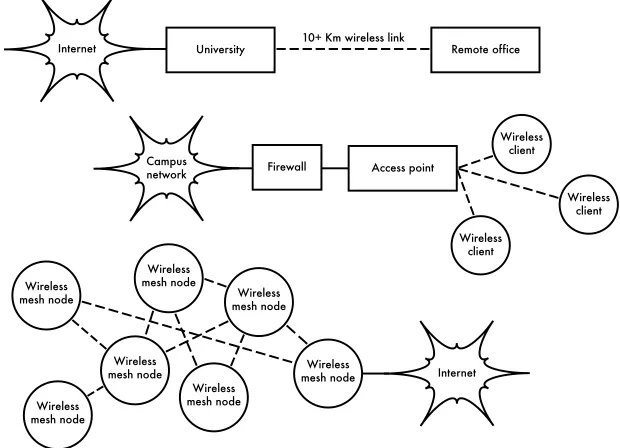
If you are a network administrator, you may wonder how wireless might fitinto your existing network infrastructure. Wireless can serve in many capaci-ties, from a simple extension (like a several kilometer Ethernet cable) to a distribution point (like a large hub). Here just a few examples of how your network can benefit from wireless technology.
Internet University Remote office
Figure 1.1: Some wireless networking examples.
Wireless networking protocols
The primary technology used for building low-cost wireless networks is cur-rently the 802.11 family of protocols, also known in many circles as Wi-Fi. The 802.11 family of radio protocols (802.11a, 802.11b, and 802.11g) have enjoyed an incredible popularity in the United States and Europe. By imple-menting a common set of protocols, manufacturers world wide have built highly interoperable equipment. This decision has proven to be a significant
own proprietary protocols, it is unlikely that wireless networking would be as inexpensive and ubiquitous as it is today.
While new protocols such as 802.16 (also known as WiMax) will likely solve some difficult problems currently observed with 802.11, they have a long way
to go to match the popularity and price point of 802.11 equipment. As equipment that supports WiMax is just becoming available at the time of this writing, we will focus primarily on the 802.11 family.
There are many protocols in the 802.11 family, and not all are directly related to the radio protocol itself. The three wireless standards currently imple-mented in most readily available gear are:
• 802.11b. Ratified by the IEEE on September 16, 1999, 802.11b is
proba-bly the most popular wireless networking protocol in use today. Millions of devices supporting it have shipped since 1999. It uses a modulation called Direct Sequence Spread Spectrum (DSSS) in a portion of the ISM band from 2.400 to 2.495GHz. It has a maximum rate of 11 Mbps, with actual usable data speeds up to about 5 Mbps.
• 802.11g. As it wasnt finalized until June 2003, 802.11g is a relative
late-comer to the wireless marketplace. Despite the late start, 802.11g is now the de facto standard wireless networking protocol as it now ships as a standard feature on virtually all laptops and most handheld devices. 802.11g uses the same ISM range as 802.11b, but uses a modulation scheme called Orthogonal Frequency Division Multiplexing (OFDM). It has a maximum data rate of 54 Mbps (with usable throughput of about 22Mbps), and can fall back to 11Mbps DSSS or slower for backwards compatibility with the hugely popular 802.11b.
• 802.11a. Also ratified by the IEEE on September 16, 1999, 802.11a uses
OFDM. It has a maximum data rate of 54Mbps, with actual throughput of up to 27Mbps. 802.11a operates in the ISM band between 5.745 and 5.805 GHz, and in a portion of the UNII band between 5.150 and 5.320GHz. This makes it incompatible with 802.11b or 802.11g, and the higher frequency means shorter range compared to 802.11b/g at the same power. While this portion of the spectrum is relatively unused compared to 2.4GHz, it is unfortunately only legal for use in a few parts of the world. Check with your local authorities before using 802.11a equipment, particu-larly in outdoor applications. 802.11a equipment is still quite inexpensive, but is not nearly as popular as 802.11b/g.
In addition to the above standards, there are a number of vendor-specific exten-sions to equipment, touting higher speeds, stronger encryption, and increased range. Unfortunately these extensions will not operate between equipment from different manufacturers, and purchasing them will effectively lock you into that vendor for every part of your network. New equipment and standards (such as
802.11y, 802.11n, 802.16, MIMO and WiMAX) promise significant increases
in speed and reliability, but this equipment is just starting to ship at the time of this writing, and availability and vendor interoperability is still uncertain.
Due to the ubiquity of equipment and unlicensed nature of the 2.4GHz ISM band, this book will concentrate on building networks using 802.11b and 802.11g.
Question & Answer
If you are new to wireless networking, you likely have a number of questions about what the technology can do and what it will cost. Here are some com-monly asked questions, with answers and suggestions on the listed page.
Power
• How can I supply power to my radio equipment, if there is no grid power available?Page 211
• Do I need to run a power cable all the way up the tower? Page 250
• How can I use solar panel to power my wireless node while keeping it on-line overnight? Page 217
• How long will my access point run on a battery? Page 238
• Can I use a wind generator to power my equipment at night? Page 212
Management
• How much bandwidth will I need to purchase for my users? Page 65
• How can I monitor and manage remote access points from my office?
Page 174
• What do I do when the network breaks? Page 174, 267
• What are the most common problems encountered on wireless networks, and how do I fix them? Page 267
Distance
• How good is the range of my access point? Page 67
• Is there any formula I can use to know how far I can go with a given access point? Page 67
• How can I know if a remote place can be connected to Internet using a wireless link? Page 67
• The manufacturer says my access point has a range of 300 meters. Is that true? Page 67
• How can I provide wireless connectivity to many remote clients, spread all around the city? Page 53
• Is it true that I can reach a much greater distance adding a tin can or alu-minum foil to my AP's antenna? Page 116
• Can I use wireless to connect to a remote site and share a single central Internet connection? Page 51
• My wireless link looks like it will be too long to work well. Can I use a repeater in the middle to make it better? Page 77
• Should I use an amplifier instead? Page 115
Installation
• How can I install my indoor AP on the top of a mast on my roof? Page 249
• Is it really useful to add a lightning protector and proper grounding to my antenna mast, or can I go without them? Page 263
• Can I build an antenna mast by myself? How high can I go? Page 251
• Why does my antenna work much better when I mount it “sideways”? Page 13
• Which channel should I use? Page 15
• Will radio waves travel through buildings and trees? What about people? Page 16
• Will radio waves travel through a hill that is in the way? Page 17 • How do I build a mesh network? Page 56
• What kind of antenna is the best one for my network? Page 102
• Can I build an access point using a recycled PC? Page 143 • How can I install Linux on my AP? Why should I do so? Page 152
Money
• How can I know if a wireless link is achievable with a limited amount of money?Page 281
• Which is the best AP with the lowest price? Page 137
• How can I track and bill customers for using my wireless network? Page165, 190
Partners and Customers
• If I am supplying connectivity, do I still need service from an ISP? Why? Page 27
• How many customers do I need to cover my costs? Page 287
• How many customers will my wireless network support? Page 65
• How do I make my wireless network go faster? Page 79
• Is my Internet connection as fast as it can be? Page 90
Security
• How can I protect my wireless network from unauthorized access? Page157 • Is it true that a wireless network is always insecure and open to attacks by
hackers?Page 160
• Is it true that the use of open source software makes my network less se-cure?Page 167
• How can I see what is happening on my network? Page 174
Information and Licensing
• What other books should I read to improve my wireless networking skills? Page 355
• Where can I find more information online? Page 349, http://wndw.net/
2
A Practical Introduction to
Radio Physics
Wireless communications make use of electromagnetic waves to send sig-nals across long distances. From a users perspective, wireless connections are not particularly different from any other network connection: your web browser, email, and other applications all work as you would expect. But radio waves have some unexpected properties compared to Ethernet cable. For example, its very easy to see the path that an Ethernet cable takes: lo-cate the plug sticking out of your computer, follow the cable to the other end, and youve found it! You can also be confident that running many Ethernet
cables alongside each other wont cause problems, since the cables effec-tively keep their signals contained within the wire itself.
But how do you know where the waves emanating from your wireless card are going? What happens when these waves bounce off of objects in the room or other buildings in an outdoor link? How can several wireless cards be used in the same area without interfering with each other?
In order to build stable high-speed wireless links, it is important to understand how radio waves behave in the real world.
What is a wave?
We are all familiar with vibrations or oscillations in various forms: a pendu-lum, a tree swaying in the wind, the string of a guitar - these are all examples of oscillations.
What they have in common is that something, some medium or object, is swinging in a periodic manner, with a certain number of cycles per unit of time. This kind of wave is sometimes called a mechanical wave, since it is defined by the motion of an object or its propagating medium.
When such oscillations travel (that is, when the swinging does not stay bound to one place) then we speak of waves propagating in space. For ex-ample, a singer singing creates periodic oscillations in his or her vocal cords. These oscillations periodically compress and decompress the air, and this periodic change of air pressure then leaves the singers mouth and travels, at the speed of sound. A stone plunging into a lake causes a disturbance, which then travels across the lake as a wave.
A wave has a certain speed, frequency, and wavelength. These are con-nected by a simple relation:
Speed = Frequency * Wavelength
The wavelength (sometimes referred to as lambda,) is the distance meas-ured from a point on one wave to the equivalent part of the next, for example from the top of one peak to the next. The frequency is the number of whole waves that pass a fixed point in a period of time. Speed is measured in
meters/second, frequency is measured in cycles per second (or Hertz, ab-breviatedHz), and wavelength is measured in meters.
For example, if a wave on water travels at one meter per second, and it oscil-lates five times per second, then each wave will be twenty centimeters long:
1 meter/second = 5 cycles/second * W W = 1 / 5 meters
W = 0.2 meters = 20 cm
Waves also have a property called amplitude. This is the distance from the center of the wave to the extreme of one of its peaks, and can be thought of as the “height” of a water wave. The relationship between frequency, wave-length, and amplitude are shown in Figure 2.1.
Waves in water are easy to visualize. Simply drop a stone into the lake and you can see the waves as they move across the water over time. In the case of electromagnetic waves, the part that might be hardest to understand is: “What is it that is oscillating?”
In order to understand that, you need to understand electromagnetic forces.
amplitude
amplitude wavelength ( )
wavelength ( )
time: 1 second
Figure 2.1: Wavelength, amplitude, and frequency. For this wave, the frequency is 2 cycles per second, or 2 Hz.
Electromagnetic forces
Electromagnetic forces are the forces between electrical charges and cur-rents. Our most direct access to those is when our hand touches a door handle after walking on synthetic carpet, or brushing up against an electrical fence. A more powerful example of electromagnetic forces is the lightning we see during thunderstorms. The electrical force is the force between electri-cal charges. The magnetic force is the force between electrielectri-cal currents.
Electrons are particles that carry a negative electrical charge. There are other particles too, but electrons are responsible for most of what we need to know about how radio behaves.
Let us look at what is happening in a piece of straight wire, in which we push the electrons from one and to the other and back, periodically. At one mo-ment, the top of the wire is negatively charged - all the negative electrons are gathered there. This creates an electric field from plus to minus along the
wire. The next moment, the electrons have all been driven to the other side, and the electric field points the other way. As this happens again and again,
the electric field vectors (arrows from plus to minus) are leaving the wire, so
to speak, and are radiated out into the space around the wire.
What we have just described is known as a dipole (because of the two poles, plus and minus), or more commonly adipole antenna. This is the simplest form of omnidirectional antenna. The motion of the electric field is commonly
referred to as an electromagnetic wave.
Let us come back to the relation:
In the case of electromagnetic waves, the speed is c, the speed of light.
c = 300,000 km/s = 300,000,000 m/s = 3*108 m/s
c = f *
Electromagnetic waves differ from mechanical waves in that they require no medium in which to propagate. Electromagnetic waves will even propagate through the vacuum of space.
Powers of ten
In physics, math, and engineering, we often express numbers by powers of ten. We will meet these terms again, e.g. in Giga-Hertz (GHz), Centi-meters (cm), Micro-seconds (s), and so on.
Powers of Ten
Nano- 10-9 1/1000000000 n
Micro- 10-6 1/1000000 μ
Milli- 10-3 1/1000 m
Centi- 10-2 1/100 c
Kilo- 103 1 000 k
Mega- 106 1 000 000 M
Giga- 109 1 000 000 000 G
Knowing the speed of light, we can calculate the wavelength for a given fre-quency. Let us take the example of the frequency of 802.11b wireless net-working, which is
f = 2.4 GHz
= 2,400,000,000 cycles / second wavelength lambda () = c / f
= 3*108 / 2.4*109
= 1.25*10-1 m
= 12.5 cm
Frequency and wavelength determine most of an electromagnetic waves be-havior, from antennas that we build to objects that are in the way of the networks we intend to run. They are responsible for many of the differences between
ferent standards we might be choosing. Therefore, an understanding of the basic ideas of frequency and wavelength helps a lot in practical wireless work.
Polarization
Another important quality of electromagnetic waves is polarization. Polari-zation describes the direction of the electrical field vector.
If you imagine a vertically aligned dipole antenna (the straight piece of wire), electrons only move up and down, not sideways (because there is no room to move) and thus electrical fields only ever point up or down, vertically. The field leaving the wire and traveling as a wave has a strict linear (and in this
case, vertical) polarization. If we put the antenna flat on the ground, we
would find horizontal linear polarization.
direction of propagation
magnetic field
electric field
Figure 2.2: Electric field and complementary magnetic field components of an
elec-tromagnetic wave. Polarization describes the orientation of the electric field.
Linear polarization is just one special case, and is never quite so perfect: in gen-eral, we will always have some component of the field pointing other directions too. The most general case is elliptic polarization, with the extremes of linear (only one direction) and circular polarizations (both directions at equal strength).
As one can imagine, polarization becomes important when aligning anten-nas. If you ignore polarization, you might have very little signal even though you have the strongest antennas. We call this polarization mismatch.
The electromagnetic spectrum
Electromagnetic waves span a wide range of frequencies (and, accordingly, wavelengths). This range of frequencies and wavelengths is called the elec-tromagnetic spectrum. The part of the spectrum most familiar to humans is probably light, the visible portion of the electromagnetic spectrum. Light lies roughly between the frequencies of 7.5*1014 Hz and 3.8*1014 Hz,
We are also regularly exposed to other regions of the electromagnetic spec-trum, including Alternating Current (AC) or grid electricity at 50/60 Hz, Ul-traviolet (on the higher frequencies side of visible light), Infrared (on the lower frequencies side of visible light), X-Rays / Roentgen radiation, and many oth-ers. Radio is the term used for the portion of the electromagnetic spectrum in which waves can be generated by applying alternating current to an an-tenna. This is true for the range from 3 Hz to 300 GHz, but in the more nar-row sense of the term, the upper frequency limit would be 1 GHz.
When talking about radio, many people think of FM radio, which uses a fre-quency around 100 MHz. In between radio and infrared we find the region of
microwaves - with frequencies from about 1 GHz to 300 GHz, and wave-lengths from 30 cm to 1 mm.
The most popular use of microwaves might be the microwave oven, which in fact works in exactly the same region as the wireless standards we are deal-ing with. These regions lie within the bands that are bedeal-ing kept open for gen-eral unlicensed use. This region is called the ISM band, which stands for Industrial, Scientific, and Medical. Most other parts of the electromagnetic
spectrum are tightly controlled by licensing legislation, with license values being a huge economic factor. This goes especially for those parts of the spectrum that are suitable for broadcast (TV, radio) as well as voice and data communication. In most countries, the ISM bands have been reserved for unlicensed use.
The frequencies most interesting to us are 2.400 - 2.495 GHz, which is used by the 802.11b and 802.11g radio standards (corresponding to wavelengths of about 12.5 cm). Other commonly available equipment uses the 802.11a standard, which operates at 5.150 - 5.850 GHz (corresponding to wave-lengths of about 5 to 6 cm).
Bandwidth
A term you will meet often in radio physics is bandwidth. Bandwidth is sim-ply a measure of frequency range. If a range of 2.40 GHz to 2.48 GHz is used by a device, then the bandwidth would be 0.08 GHz (or more commonly stated as 80MHz).
It is easy to see that the bandwidth we define here is closely related to the
amount of data you can transmit within it - the more room in frequency space, the more data you can fit in at a given moment. The term bandwidth is
often used for something we should rather call a data rate, as in “my Internet connection has 1 Mbps of bandwidth”, meaning it can transmit data at 1 megabit per second.
Frequencies and channels
Let us look a bit closer at how the 2.4GHz band is used in 802.11b. The spectrum is divided into evenly sized pieces distributed over the band as in-dividual channels. Note that channels are 22MHz wide, but are only sepa-rated by 5MHz. This means that adjacent channels overlap, and can inter-fere with each other. This is represented visually in Figure 2.4.
1
Figure 2.4: Channels and center frequencies for 802.11b. Note that channels 1, 6, and 11 do not overlap.
For a complete list of channels and their center frequencies for 802.11b/g and 802.11a, see Appendix B.
Behavior of radio waves
There are a few simple rules of thumb that can prove extremely useful when making first plans for a wireless network:
• The longer the wavelength, the further it goes
• The longer the wavelength, the better it travels through and around things
All of these rules, simplified as they may be, are rather easy to understand by
example.
Longer waves travel further
Assuming equal power levels, waves with longer wavelengths tend to travel further than waves with shorter wavelengths. This effect is often seen in FM radio, when comparing the range of an FM transmitter at 88MHz to the range at 108MHz. Lower frequency transmitters tend to reach much greater dis-tances than high frequency transmitters at the same power.
Longer waves pass around obstacles
A wave on water which is 5 meters long will not be stopped by a 5 mm piece of wood sticking out of the water. If instead the piece of wood were 50 me-ters big (e.g. a ship), it would be well in the way of the wave. The distance a wave can travel depends on the relationship between the wavelength of the wave and the size of obstacles in its path of propagation.
It is harder to visualize waves moving “through” solid objects, but this is the case with electromagnetic waves. Longer wavelength (and therefore lower frequency) waves tend to penetrate objects better than shorter wavelength (and therefore higher frequency) waves. For example, FM radio (88-108MHz) can travel through buildings and other obstacles easily, while shorter waves (such as GSM phones operating at 900MHz or 1800MHz) have a harder time penetrating buildings. This effect is partly due to the dif-ference in power levels used for FM radio and GSM, but is also partly due to the shorter wavelength of GSM signals.
Shorter waves can carry more data
The faster the wave swings or beats, the more information it can carry - every beat or cycle could for example be used to transport a digital bit, a '0' or a '1', a 'yes' or a 'no'.
There is another principle that can be applied to all kinds of waves, and which is extremely useful for understanding radio wave propagation. This principle is known as the Huygens Principle, named after Christiaan Huy-gens, Dutch mathematician, physicist and astronomer 1629 - 1695.
Imagine you are taking a little stick and dipping it vertically into a still lake's surface, causing the water to swing and dance. Waves will leave the center of the stick - the place where you dip in - in circles. Now, wherever water par-ticles are swinging and dancing, they will cause their neighbor parpar-ticles to do
the same: from every point of disturbance, a new circular wave will start. This is, in simple form, the Huygens principle. In the words of wikipedia.org:
“The Huygens' principle is a method of analysis applied to problems of wave propagation in the far field limit. It recognizes that each point of an advancing wave front is in fact the center of a fresh disturbance and the source of a new train of waves; and that the advancing wave as a whole may be regarded as the sum of all the secondary waves arising from points in the medium already traversed. This view of wave propagation helps better understand a variety of wave phenomena, such as diffrac-tion.”
This principle holds true for radio waves as well as waves on water, for sound as well as light - only for light the wavelength is far too short for human be-ings to actually see the effects directly.
This principle will help us to understand diffraction as well as Fresnel zones, the need for line of sight as well as the fact that sometimes we seem to be able to go around corners, with no line of sight.
Let us now look into what happens to electromagnetic waves as they travel.
Absorption
When electromagnetic waves go through 'something' (some material), they generally get weakened or dampened. How much they lose in power will de-pend on their frequency and of course the material. Clear window glass is obviously transparent for light, while the glass used in sunglasses filter out
quite a share of the light intensity and also the ultraviolet radiation.
Often, an absorption coefficient is used to describe a materials impact on
radiation. For microwaves, the two main absorbent materials are:
• Metal. Electrons can move freely in metals, and are readily able to swing and thus absorb the energy of a passing wave.
• Water. Microwaves cause water molecules to jostle around, thus taking away some of the waves energy1.
For the purpose of practical wireless networking, we may well consider metal and water perfect absorbers: we will not be able to go through them
though thin layers of water will let some power pass). They are to microwave what a brick wall is to light. When talking about water, we have to remember that it comes in different forms: rain, fog and mist, low clouds and so forth all will be in the way of radio links. They have a strong influence, and in many
circumstances a change in weather can bring a radio link down.
There are other materials that have a more complex effect on radio absorp-tion. For trees and wood, the amount of absorption depends on how much water they contain. Old dead dry wood is more or less transparent, wet fresh wood will absorb a lot.
Plastics and similar materials generally do not absorb a lot of radio energy- but this varies depending on the frequency and type of material. Before you build a component from plastic (e.g. weather protection for a radio device and its antennas), it is always a good idea to measure and verify that the ma-terial does not absorb radio energy around 2.4GHz. One simple method of measuring the absorption of plastic at 2.4GHz is to put a sample in a micro-wave oven for a couple of minutes. If the plastic heats up, then it absorbs radio energy and should not be used for weatherproofing.
Lastly, let us talk about ourselves: humans (as well as other animals) are largely made out of water. As far as radio networking is concerned, we may well be described as big bags of water, with the same strong absorption. Ori-enting an office access point in such a way that its signal must pass through
many people is a key mistake when building office networks. The same goes
for hotspots, cafe installations, libraries, and outdoor installations.
Reflection
Just like visible light, radio waves are reflected when they come in contact
with materials that are suited for that: for radio waves, the main sources of reflection are metal and water surfaces. The rules for reflection are quite
simple: the angle at which a wave hits a surface is the same angle at which it gets deflected. Note that in the eyes of a radio wave, a dense grid of bars
acts just the same as a solid surface, as long as the distance between bars is small compared to the wavelength. At 2.4GHz, a one cm metal grid will act much the same as a metal plate.
Although the rules of reflection are quite simple, things can become very
complicated when you imagine an office interior with many many small metal
objects of various complicated shapes. The same goes for urban situations: look around you in city environment and try to spot all of the metal objects. This explains why multipath effects (i.e. signal reaching their target along different paths, and therefore at different times) play such an important role in wireless networking. Water surfaces, with waves and ripples changing all the
time, effectively make for a very complicated reflection object which is more
or less impossible to calculate and predict precisely.
i r
i = r
Figure 2.5: Reflection of radio waves. The angle of incidence is always equal to the angle of reflection. A parabolic uses this effect to concentrate radio waves spread
out over its surface in a common direction.
We should also add that polarization has an impact: waves of different po-larization in general will be reflected differently.
We use reflection to our advantage in antenna building: e.g. we put huge
pa-rabolas behind our radio transmitter/receiver to collect and bundle the radio signal into a fine point.
Diffraction
Diffraction is the apparent bending of waves when hitting an object. It is the effect of “waves going around corners”.
Straight wave front Diffraction
Figure 2.6: Diffraction through a narrow slit.
The Huygens Principle provides one model for understanding this behavior. Imagine that at any given instant, every point on a wavefront can be consid-ered the starting point for a spherical “wavelet”. This idea was later extended by Fresnel, and whether it adequately describes the phenomenon is still a matter of debate. But for our purposes, the Huygens model describes the effect quite well.
Potential spherical wavelets Diffraction
Figure 2.7: The Huygens Principle.
Through means of the effect of diffraction, waves will “bend” around corners or through an opening in a barrier. The wavelengths of visible light are far too small for humans to observe this effect directly. Microwaves, with a wave-length of several centimeters, will show the effects of diffraction when waves hit walls, mountain peaks, and other obstacles. It seems as if the obstruction causes the wave to change its direction and go around corners.
Figure 2.8: Diffraction over a mountain top.
Note that diffraction comes at the cost of power: the energy of the diffracted wave is significantly less than that of the wavefront that caused it. But in
some very specific applications, you can take advantage of the diffraction
effect to circumvent obstacles.
Interference
When working with waves, one plus one does not necessarily equal two. It can also result in zero.
+
+
=
=
Figure 2.9: Constructive and destructive interference.
This is easy to understand when you draw two sine waves and add up the amplitudes. When peak hits peak, you will have maximum results (1 + 1 = 2). This is called constructive interference. When peak hits valley, you will have complete annihilation ((1 + (-)1 = 0) - destructive interference.
In order for whole trains of waves to add up or cancel each other out per-fectly, they would have to have the exact same wavelength and a fixed phase
relation, this means fixed positions from the peaks of the one wave to the
other's.
In wireless technology, the word Interference is typically used in a wider sense, for disturbance through other RF sources, e.g. neighboring channels. So, when wireless networkers talk about interference they typically talk about all kinds of disturbance by other networks, and other sources of microwave. Interference is one of the main sources of difficulty in building wireless links,
especially in urban environments or closed spaces (such as a conference space) where many networks may compete for use of the spectrum.
Whenever waves of equal amplitude and opposite phase cross paths, the wave is annihilated and no signal can be received. The much more common case is that waves will combine to form a completely garbled waveform that cannot be effectively used for communication. The modulation techniques and use of multiple channels help to deal with the problem of interference, but does not completely eliminate it.
Line of sight
The term line of sight, often abbreviated as LOS, is quite easy to under-stand when talking about visible light: if we can see a point B from point A where we are, we have line of sight. Simply draw a line from A to B, and if nothing is in the way, we have line of sight.
Things get a bit more complicated when we are dealing with microwaves. Remember that most propagation characteristics of electromagnetic waves scale with their wavelength. This is also the case for the widening of waves as they travel. Light has a wavelength of about 0.5 micrometers, microwaves as used in wireless networking have a wavelength of a few centimeters. Consequently, their beams are a lot wider - they need more space, so to speak.
Note that visible light beams widen just the same, and if you let them travel long enough, you can see the results despite of their short wavelength. When pointing a well focussed laser at the moon, its beam will widen to well over 100 meters in radius by the time it reaches the surface. You can see this effect for yourself using an inexpensive laser pointer and a pair of binoculars on a clear night. Rather than pointing at the moon, point at a distant moun-tain or unoccupied structure (such as a water tower). The radius of your beam will increase as the distance increases.
The line of sight that we need in order to have an optimal wireless connection from A to B is more than just a thin line - its shape is more like that of a cigar, an ellipse. Its width can be described by the concept of Fresnel zones.
Understanding the Fresnel zone
The exact theory of Fresnel (pronounced “Fray-nell”) zones is quite compli-cated. However, the concept is quite easy to understand: we know from the Huygens principle that at each point of a wavefront new circular waves start, We know that microwave beams widen as they leave the antenna. We know that waves of one frequency can interfere with each other. Fresnel zone the-ory simply looks at a line from A to B, and then at the space around that line that contributes to what is arriving at point B. Some waves travel directly from A to B, while others travel on paths off axis. Consequently, their path is longer, introducing a phase shift between the direct and indirect beam. Whenever the phase shift is one full wavelength, you get constructive inter-ference: the signals add up optimally. Taking this approach and calculating accordingly, you find there are ring zones around the direct line A to B which
contribute to the signal arriving at point B.
Fresnel radius
Partial obstruction Line of sight
Figure 2.10: The Fresnel zone is partially blocked on this link, although the visual line of sight appears clear.
Note that there are many possible Fresnel zones, but we are chiefly
con-cerned with zone 1. If this area were partially blocked by an obstruction, e.g. a tree or a building, the signal arriving at the far end would be diminished. When building wireless links, we therefore need to be sure that these zones be kept free of obstructions. Of course, nothing is ever perfect, so usually in wireless networking we check that about 60 percent of the radius of the first
Fresnel zone should be kept free.
Here is one formula for calculating the first Fresnel zone:
r = 17.31 * sqrt((d1*d2)/(f*d))
of the zone, not the height above ground. To calculate the height above ground, you need to subtract the result from a line drawn directly between the tops of the two towers.
For example, lets calculate the size of the first Fresnel zone in the middle of
a 2km link, transmitting at 2.437GHz (802.11b channel 6):
r = 17.31 sqrt((1000 * 1000) / (2437 * 2000)) r = 17.31 sqrt(1000000 / 4874000)
r = 7.84 meters
Assuming both of our towers were ten meters tall, the first Fresnel zone
would pass just 2.16 meters above ground level in the middle of the link. But how tall could a structure at that point be to clear 60% of the first zone?
r = 0.6 * 17.31 sqrt((1000 * 1000) / (2437 * 2000)) r = 0.6 * 17.31 sqrt(600000 / 4874000)
r = 4.70 meters
Subtracting the result from 10 meters, we can see that a structure 5.3 meters tall at the center of the link would block up to 40% of the first Fresnel zone.
This is normally acceptable, but to improve the situation we would need to position our antennas higher up, or change the direction of the link to avoid the obstacle.
Power
Any electromagnetic wave carries energy - we can feel that when we enjoy (or suffer from) the warmth of the sun. The amount of energy received in a certain amount of time is called power. The power P is of key importance for making wireless links work: you need a certain minimum power in order for a receiver to make sense of the signal.
We will come back to details of transmission power, losses, gains and radio sensitivity in Chapter 3. Here we will briefly discuss how the power P is de-fined and measured.
The electric field is measured in V/m (potential difference per meter), the
power contained within it is proportional to the square of the electric field
P ~ E2
Practically, we measure the power by means of some form of receiver, e.g. an antenna and a voltmeter, power meter, oscilloscope, or even a radio card and laptop. Looking at the signals power directly means looking at the square of the signal in Volts.
Calculating with dB
By far the most important technique when calculating power is calculating with decibels (dB). There is no new physics hidden in this - it is just a con-venient method which makes calculations a lot simpler.
The decibel is a dimensionless unit2, that is, it defines a relationship between
two measurements of power. It is defined by:
dB = 10 * Log (P1 / P0)
where P1 and P0 can be whatever two values you want to compare. Typi-cally, in our case, this will be some amount of power.
Why are decibels so handy to use? Many phenomena in nature happen to behave in a way we call exponential. For example, the human ear senses a sound to be twice as loud as another one if it has ten times the physical signal.
Another example, quite close to our field of interest, is absorption. Suppose
a wall is in the path of our wireless link, and each meter of wall takes away half of the available signal. The result would be:
0 meters = 1 (full signal) 1 meter = 1/2
2 meters = 1/4 3 meters = 1/8 4 meters = 1/16
n meters = 1/2n = 2-n
This is exponential behavior.
But once we have used the trick of applying the logarithm (log), things be-come a lot easier: instead of taking a value to the n-th power, we just multiply by n. Instead of multiplying values, we just add.
Here are some commonly used values that are important to remember:
+3 dB = double power -3 dB = half the power
+10 dB = order of magnitude (10 times power) -10 dB = one tenth power
In addition to dimensionless dB, there are a number of relative definitions
that are based on a certain base value P0. The most relevant ones for us are:
dBm relative to P0 = 1 mW
dBi relative to an ideal isotropic antenna
An isotropic antennais a hypothetical antenna that evenly distributes power in all directions. It is approximated by a dipole, but a perfect isotropic an-tenna cannot be built in reality. The isotropic model is useful for describing the relative power gain of a real world antenna.
Another common (although less convenient) convention for expressing power is in milliwatts. Here are equivalent power levels expressed in milli-watts and dBm:
1 mW = 0 dBm 2 mW = 3 dBm 100 mW = 20 dBm 1 W = 30 dBm
Physics in the real world
Dont worry if the concepts in this chapter seem challenging. Understanding how radio waves propagate and interact with the environment is a complex
field of study in itself. Most people find it difficult to understand phenomenon
that they cant even see with their own eyes. By now you should understand that radio waves dont travel in a straight, predictable path. To make reliable communication networks, you will need to be able to calculate how much power is needed to cross a given distance, and predict how the waves will travel along the way.
There is much more to learn about radio physics than we have room for here. For more information about this evolving field, see the resources list in
Ap-pendix A.
3
Network Design
Before purchasing equipment or deciding on a hardware platform, you should have a clear idea of the nature of your communications problem. Most likely, you are reading this book because you need to connect computer networks together in order to share resources and ultimately reach the larger global Internet. The network design you choose to implement should fit the
commu-nications problem you are trying to solve. Do you need to connect a remote site to an Internet connection in the center of your campus? Will your network likely grow to include several remote sites? Will most of your network com-ponents be installed in fixed locations, or will your network expand to include
hundreds of roaming laptops and other devices?
In this chapter, we will begin with a review of the networking concepts that define TCP/IP, the primary family of networking protocols currently used on
the Internet. We will then see examples of how other people have built wire-less networks to solve their communication problems, including diagrams of the essential network structure. Finally, we will present several common methods for getting your information to flow efficiently through your network
and on to the rest of the world.
Networking 101
TCP/IP refers to the suite of protocols that allow conversations to happen on the global Internet. By understanding TCP/IP, you can build networks that will scale to virtually any size, and will ultimately become part of the global Internet.
If you are already comfortable with the essentials of TCP/IP networking (in-cluding addressing, routing, switches, firewalls, and routers), you may want
to skip ahead to Designing the Physical Network on Page 51. We will now review the basics of Internet networking.
Introduction
Venice, Italy is a fantastic city to get lost in. The roads are mere foot paths that cross water in hundreds of places, and never go in a simple straight line. Postal carriers in Venice are some of the most highly trained in the world, specializing in delivery to only one or two of the six sestieri (districts) of Ven-ice. This is necessary due to the intricate layout of that ancient city. Many people find that knowing the location of the water and the sun is far more
useful than trying to find a street name on a map.
Figure 3.1: Another kind of network mask.
Imagine a tourist who happens to find papier-mâché mask as a souvenir, and
wants to have it shipped from the studio in S. Polo, Venezia to an office in
Seattle, USA. This may sound like an ordinary (or even trivial) task, but let's look at what actually happens.
The artist first packs the mask into a shipping box and addresses it to the
office in Seattle, USA. They then hand this off to a postal employee, who
at-taches some official forms and sends it to a central package processing hub
for international destinations. After several days, the package clears Italian customs and finds its way onto a transatlantic flight, arriving at a central
im-port processing location in the U.S. Once it clears through U.S. customs, the package is sent to the regional distribution point for the northwest U.S., then on to the Seattle postal processing center. The package eventually makes its way onto a delivery van which has a route that brings it to the proper ad-dress, on the proper street, in the proper neighborhood. A clerk at the office
accepts the package and puts it in the proper incoming mail box. Once it ar-rives, the package is retrieved and the mask itself is finally received.
The clerk at the office in Seattle neither knows nor cares about how to get to
the sestiere of S. Polo, Venezia. His job is simply to accept packages as they arrive, and deliver them to the proper person. Similarly, the postal carrier in Venice has no need to worry about how to get to the correct neighborhood in Seattle. His job is to pick up packages from his local neighborhood and for-ward them to the next closest hub in the delivery chain.
Internet
Router Router
Computer Server
Image.jpg Part 10 of 10 Image.jpg
Part 1 of 10
Figure 3.2: Internet networking. Packets are forwarded between routers until they reach their ultimate destination.
This is very similar to how Internet routing works. A message is split up into many individual packets, and are labeled with their source and destination. The computer then sends these packets to a router, which decides where to send them next. The router needs only to keep track of a handful of routes (for example, how to get to the local network, the best route to a few other local networks, and one route to a gateway to the rest of the Internet). This list of possible routes is called the routing table. As packets arrive at the router, the destination address is examined and compared against its internal routing table. If the router has no explicit route to the destination in question, it sends the packet to the closest match it can find, which is often its own
Internet gateway (via the default route). And the next router does the same, and so forth, until the packet eventually arrives at its destination.
street address, city, country, and postal code). Without this information, pack-ages are either returned to the sender or are lost in the system.
Packets can only flow through the global Internet because we have agreed
on a common addressing scheme and protocol for forwarding packets. These standard communication protocols make it possible to exchange in-formation on a global scale.
Cooperative communications
Communication is only possible when the participants speak a common lan-guage. But once the communication becomes more complex than a simple conversation between two people, protocol becomes just as important as language. All of the people in an auditorium may speak English, but without a set of rules in place to establish who has the right to use the microphone, the communication of an individuals ideas to the entire room is nearly impossi-ble. Now imagine an auditorium as big as the world, full of all of the comput-ers that exist. Without a common set of communication protocols to regulate when and how each computer can speak, the Internet would be a chaotic mess where every machine tries to speak at once.
People have developed a number of communications frameworks to address this problem. The most well-known of these is the OSI model.
The OSI model
The international standard for Open Systems Interconnection (OSI) is
de-fined by the document ISO/IEC 7498-1, as outlined by the International
Standards Organization and the International Electrotechnical Commission. The full standard is available as publication "ISO/IEC 7498-1:1994," available fromhttp://standards.iso.org/ittf/PubliclyAvailableStandards/.
The OSI model divides network traffic into a number of layers. Each layer is
independent of the layers around it, and each builds on the services provided by the layer below while providing new services to the layer above. The ab-straction between layers makes it easy to design elaborate and highly reli-able protocol stacks, such as the ubiquitous TCP/IP stack. A protocol stack is an actual implementation of a layered communications framework. The OSI model doesn't define the protocols to be used in a particular network, but
simply delegates each communications "job" to a single layer within a well-defined hierarchy.
While the ISO/IEC 7498-1 specification details how layers should interact
with each other, it leaves the actual implementation details up to the manu-facturer. Each layer can be implemented in hardware (more common for lower layers) or software. As long as the interface between layers adheres to