Enterprise Java™
with UML™
CT Arlington
Wiley Computer Publishing
To my beautiful wife Anne, you were sooo worth the wait! Always and forever,
To Bethany Carleen, our precious daughter, and my personal trainer.
To Anne Burzawa, my best friend from cradle to grave.
Publisher: Robert Ipsen Editor: Theresa Hudson
Developmental Editor: Kathryn A. Malm Managing Editor: Angela Smith
Text Design & Composition: Publishers' Design and Production Services, Inc.
Designations used by companies to distinguish their products are often claimed as trademarks. In all instances where John Wiley & Sons, Inc., is aware of a claim, the product names appear in initial capital or ALL CAPITAL LETTERS. Readers, however, should contact the appropriate companies for more complete information regarding trademarks and registration.
This book is printed on acidfree paper. ©
Copyright © 2001 by CT Arrington. All rights reserved.
Published by John Wiley & Sons, Inc.
Published simultaneously in Canada.
No part of this publication may be reproduced, stored in a retrieval system or transmitted in any form or by any means, electronic, mechanical, photocopying, recording, scanning or otherwise, except as permitted under Sections 107 or 108 of the 1976 United States Copyright Act, without either the prior written permission of the Publisher, or authorization through payment of the appropriate percopy fee to the Copyright Clearance Center, 222 Rosewood Drive, Danvers, MA 01923, (978) 7508400, fax (978) 7504744. Requests to the Publisher for permission should be addressed to the Permissions Department, John Wiley & Sons, Inc., 605 Third Avenue, New York, NY 101580012, (212) 8506011, fax (212) 8506008, EMail: PERMREQ @ WILEY.COM.
This publication is designed to provide accurate and authoritative information in regard to the subject matter covered. It is sold with the understanding that the publisher is not engaged in professional services. If professional advice or other expert assistance is required, the services of a competent professional person should be sought
Library of Congress Cataloging-in-Publication Data: ISBN: 0471386804
Printed in the United States of America.
Contents
OMG Press Advisory Board xvii OMG Press Books in Print xix About the OMG xxi
Chapter 1 Introduction to Modeling Java with the UML 1 What Is Modeling? 2 Simplification 3 Varying Perspectives 3 Common Notation 4 UML 4 The Basics 4 Modeling Software Systems with the UML 13 The Customer's Perspective 13 The Developer's Perspective 14 Modeling Process 14 Requirements Gathering 15 Analysis 15 Technology Selection 15 Architecture 15 Design and Implementation 16 The Next Step 16
Chapter 2 Gathering Requirements with UML 17 Are You Ready? 18 What Are Good Requirements? 18 Find the Right People 19 Listen to the Stakeholders 20 Develop Accessible Requirements 21 Describe Detailed and Complete Requirements 24
iv Contents
Refactor the Use Case Model 27
Guidelines for Gathering Requirements 34 Focus on the Problem 34 Don't Give Up 35 Don't Go Too Far 35 Believe in the Process 36 How to Detect Poor Requirements 37 Path 1: Excessive Schedule Pressure 38 Path 2: No Clear Vision 39 Path 3: Premature Architecture and Design 40 The Next Step 40
Chapter 3 Gathering Requirements for the Timecard Application 41 Listen to the Stakeholders 42 Build a Use Case Diagram 44 Find the Actors 44 Find the Use Cases 45 Determine the ActortoUseCase Relationships 47 Describe the Details 48 Guidelines for Describing the Details 48
Gathering More Requirements 58 Revising the Use Case Model 61 Revise the Use Case Diagram 61 Revising the Use Case Documentation 63
The Next Step 75
Chapter 4 A Brief Introduction to ObjectOriented Analysis with the UML 77 Are You Ready? 78 Solid Requirements 78 Prioritizing Use Cases 78 What Is ObjectOriented Analysis? 80 The Analysis Model 80 Relationship to Use Case Model SO Steps for ObjectOriented Analysis 81
Contents v
A Process for Describing Behavior 92 Describe the Classes 95 Guidelines for Describing Classes 95 Process for Describing Classes 97 The Next Step 101
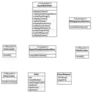
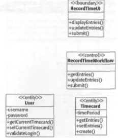
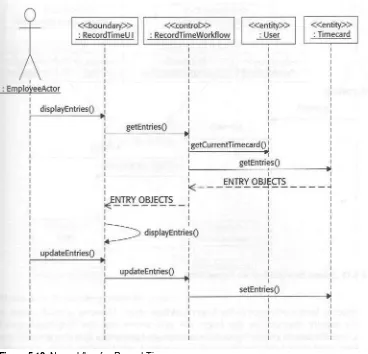
Chapter 5 Analysis Model for the Timecard Application 103 Prioritizing the Use Cases 103 The Ranking System 104 Evaluation of the Export Time Entries Use Case 107 Eva uation of the Create Charge Code Use Case 108 Eva uation of the Change Password Use Case 109 Eva uation of the Login Use Case 109 Eva uation of the Record Time Use Case 110 Eva uation of the Create Employee Use Case 111 Select Use Cases for the First Iteration 112 Discover Candidate Objects 112 Discover Entity Objects 113 Discover Boundary Objects 116 Discover Control Classes 118 Discover Lifecycle Classes 118 Describe Object Interactions 118 Add Tentative Behavior for Login 119 Build Sequence Diagrams for Login 119 Validate Sequences for Login 122 Sequence Diagrams and Class Diagrams for the
Remaining Use Cases 124 Describe Classes 126 Find Relationships for Login 127 Find Relationships for Export Time Entries 128 Find Relationships for Record Time 129 The Next Step 131
vi Contents
Deployment Constraints for User Interfaces 138 Number and Type of Users 140 Available Bandwidth 141 Types of System Interfaces 142 Performance and Scalability 143
Technology Requirements for the Timecard Application 144 Find Groups of Analysis Classes 144 User Interface Complexity 144 Deployment Constraints for User Interfaces 146 Number and Type of Users 147 Available Bandwidth 148 Types of System Interfaces 148 Performance and Scalability 148 The Next Step 152
Chapter 7 Evaluating Candidate Technologies for Boundary Classes 153 Technology Template 153 Swing 154 Gory Details 155 Strengths 165 Weaknesses 165 Compatible Technologies 165 Cost of Adoption 166 Suitability 167 Java Servlets 168
Gory Details 170 Strengths 172 Weaknesses 172 Compatible Technologies 172 Cost of Adoption 172 Suitability 173
XML 175
Contents vii
Technology Selections for the Timecard System 180 User Interface Classes 180 Conclusion 181 The Next Step 182
Chapter 8 Evaluating Candidate Technologies for Control and Entity Classes 183
RMI 183
Gory Details 184 Common Uses of RMI 188 Strengths 192 Weaknesses 192 Compatible Technologies 192 Cost of Adoption 192 JDBC 193 Gory Details 193 Strengths 196 Weaknesses 197 Compatible Technologies 198 Cost of Adoption 198 Suitability of RMI and JDBC 198
ETB 1.1 199
Gory Details 202 Strengths 205 Weaknesses 206 Compatible Technologies 206 Cost of Adoption 206 Suitability 207 Sampie Technology Selection 208 Technology Requirements 208 The Next Step 210
viii Contents
Reliability 214 Scalability 214 UML and Architecture 214 Packages 214 Package Dependency 217 Subsystems 219
Guidelines for Software Architecture 221 Cohesion 222 Coupling 222 Creating a Software Architecture 222 The Architect 222 A Process 223 Sample Architecture for the Timecard System 225 Set Goals 225 Group and Evaluate Classes 226 Show Technologies 233 Extract Subsystems 233 Evaluate against Guidelines and Goals 233 The Next Step 237
Chapter 10 Introduction to Design 239 What Is Design? 239 Are You Ready? 240
The Need for Design 240 Productivity and Morale 240 A Malleable Medium 241 Scheduling and Delegation 241 Design Patterns 241 Benefits 242
Use 243
Planning for Design 243 Establish Goals for the Entire Design 244 Establish Design Guidelines 245 Find Independent Design Efforts 246
Designing Packages or Subsystems 246 Design Efforts for the Timecard Application 247
The Next Step 248
Chapter 11 Design for the TimecardDomain and
Contents IX
Establish Goals for the Effort 250 Performance and Reliability 250 Reuse 250 Extensibility 250 Review Prior Steps 251 Review of the Analysis Model 251 Review Architectural Constraints 257 Design for Goals 258 Apply Design for Each Use Case 262 Design for the Login Use Case 262 Design for the Record Time Use Case 266 Design for the Export Time Entries Use Case 271 Evaluate the Design 273 Implementation 277 User Entity Bean 277 Timecard Entity Bean 283 LoginWorkflow Stateless Session Bean 292 RecordTimeWorkflow Stateful Session Bean 296 Supporting Classes 301 ChargeCodeHome 308 ChargeCodeWrapper.java 319 Node.java 320 The Next Step 321
Chapter 12 Design for HTML Production 323 Design Goals 324 Goal 1: Support Modular Construction of Views 324 Goal 2: Keep HTML Production Simple 324 Goal 3: Support Preferences 326 Goal 4: Extensibility and Encapsulation 326 Design to Goals 327
Design for Goal 1: Support Modular Construction of Views 327 Design for Goal 2: Keep HTML Production Simple 330 Design for Goal 3: Support Preferences 335 Design for Goal 4: Extensibility and Encapsulation 338 Filling in the Details 339 Implementation 346
X Contents
FormProducer.java 348 PageProducer.java 350 SubmitButtonProducer 351 TableProducer.java 352 TabularlnputFormProducer.java 354 TextFieldProducer.java 356 TextProducer.java 358 IConcreteProducer.java 359 ProducerFactory.java 360 FormProducerGeneric.java 364 PageProducerGeneric.java 366 TableProducerGeneric.java 368 TabularTnputFormProducerGeneric.java 369 The Next Step 371
Chapter 13 Design for the TimecardUl Package 373 Establish Design Goals 373 Extensibility 373 Testability 374 Review Prior Steps 374 Review Architectural Constraints 374 Review Analysis Model 375 Design to Goals 379 Design for Each Use Case 381 Create Design for the Login Use Case 381 Create Design for the Record Time Use Case 383 Implementation 387
LoginServlet.java 387 RecordTimeServlet.java 392 BaskServlet.java 397
The Next Step 399
Chapter 14 Design for Bill! ngSystem Interface 401 Identify Goals 401 Clarity 402 Performance and Reliability 402 Extensibility 402 Reuse Potential 402 Review of Analysis Model 402
Contents XI
Design 403 Sequence Diagram for Export Specific Users 406 Sequence Diagram for Export All Users 406 Participating Classes 406 Implementation 407 ExportCriteria.java 407 ExportFile.java 412 Exp or tTimeEntr ie s A pplic ation.java 414 Conclusion 417
Appendix A Visual Glossary 419
Appendix B Additional Resources 435
Appendix C The CDROM 439
Acknowledgments
Thanks to all of my former coworkers and bosses at Number Six Software, for their support, reviews, and insights. Special thanks are due to the cofounders, Rob Daly and Brian Lyons, for creating an amazing environ ment in which to work and to stretch professionally. Special thanks to Susan Cardinale, Greg Gurley, Kevin Puscas, Hugo Scavino, and Eric Tavella for their feedback and encouragement.
Thanks to John Haynes for his careful review and commentary. Thanks to Mike Janiszewski and Jennifer. Horn, for their review, encourage
ment, and support. Friends in need are friends in deed.
Many thanks to the fine professionals from John Wiley and Sons; Terri Hud son, Kathryn Malm, Angela Smith, Janice Borzendowski, and Brian Snapp. Kathryn deserves special recognition for her ability to edit techni cal material while keeping an exhausted author motivated. Thanks to the Wrights, for their consistent friendship, encouragement, and
lawn advice. We couldn't ask for better neighbors.
Thanks to my parents, for fostering a lifetime obsession with the printed word.
I will never be able to sufficiently thank my family for permitting me this most selfish endeavor. How many evenings and weekends did I take away? How many mornings did T wake bleary eyed and grumpy from too little sleep and too little progress? This book truly was a once in a lifetime opportunity for the skinny (formerly) kid who read too much, and you two made it possible. Thank you!
About the Author
CT Arlington has spent the last nine years developing clientserver software systems ranging from currency options valuation to barge scheduling to com plex corporate intranets. Over the last five years, he has become convinced that the combination of Object Oriented Analysis and Design and good Soft ware Engineering practices can yield excellent systems in a sane work environment.
CT's focus over the last few years has been architecting and developing sys tems in Java. These tended to be 3+ tier server side applications for use in cor porate intranets. His favorite technologies for such systems include Servlets, XML, EJB, and Object to Relational persistence frameworks. He also had the good fortune to be the lead developer for a slick Java data visualization tool for barge scheduling. This project used Swing and a commercial 2D graphics framework and convinced him that Java applications can meet demanding performance goals.
In these pursuits, CT has depended heavily on books on OO design, design patterns, software engineering, Java, CORBA, EJB, and XML. While he has read and enjoyed many great books over the years, he cannot imagine devel oping software without Grady Booch's OOAD with Applications, the Gang of Four's Design Patterns, Steve McConnell's Rapid Development and of course, Patrick Chan's The Java Class Libraries.
CT is an architect and development manager with Capital One in Northern Virginia.
CT is a former Rational Software certified instructor and a Sun certified Java Programmer, Developer, and Architect. He holds a Bachelor's in Applied Mathematics from the University of Maryland at Baltimore County.
OMG Press Advisory Board
Karen D. Boucher Executive Vice President The Standish Group
Carol C. Hurt
President and Chief Executive Officer 2AB, Inc.
Ian Foster Business Director Concept Five Technologies
Michael Gurevich Chief Architect 724 Solutions
V. "Juggy" Jagannathan, Ph.D.
Senior Vice President of Research and Development and Chief Technology Officer
CareFlow! Net, Inc.
Cris Kobryn
Chief Scientist and Senior Director Inline Software
Nilo Mitra, Ph.D. Principal System Engineer Ericsson
Richard Mark Soley, Ph.D. Chairman and Chief Executive Officer Object Management Group, Inc.
Introduction to Modeling
Java with the UML
As Java completes its move from a novelty language to the language of choice for Web enabled enterprise computing, Java developers are faced with many opportunities as well as many challenges. We must produce systems that scale as the underlying busi ness grows and evolves at Web speed. Our customers' appetite for functionality, scala bility, usability, extensibility, and reliability rises each year.
Fortunately, Java provides a lot of support as we struggle to meet these demands. First and perhaps foremost, Java is a small, tightly written objectoriented language with excellent support for exception handling and concurrency built in. Of course, this language runs on a pi a tformindependent virtual machine that allows Java systems to run on everything from a PalmPilot to a Web browser to an AS400, with about a dozen operating systems in between. From this solid foundation. Sun built and evolved one of the most impressive class libraries you could ever ask for, including support for internationalization, calendar management, database access, image manipulation, net working, user interfaces, 2D and 3D graphics, and more. Finally, Enterprise JavaBeans and Java 2 Enterprise Edition provide specifications for true crossplatform enterprise computing. Many of the problems that have plagued enterprise developers for decades, such as objecttorelational persistence, object caching, data integrity, and resource management are being addressed with newfound vigor. These specifications, and the application servers that implement them, allow us to leverage a wealth of academic research and practical experience. We are better equipped to develop enterprise sys tems than ever before.
2 Enterprise Java with UML
However, powerful tools do not guarantee success. Before developers can harness the enormous power of enterprise Java technology, they need a clear understanding of the problem and a clear plan for the solution. In order to develop this understanding, they need a way to visualize the system and communicate their decisions and creations to a wide audience. Fortunately, the last few decades have also seen dramatic progress in our ability to understand and model objectoriented systems. The Unified Modeling Language (UML) is an open standard notation that allows developers to build visual representations of software systems. These models enable developers to devise elegant solutions, share ideas, and track decisions throughout the entire development cycle. Also, tools for creating, reverseengineering, and distributing software models in UML have matured greatly over the past two years, to the point where modeling can be a seamless part of a development lifecycle.
This book describes software modeling with the UML, and demonstrates how devel opers can use UML throughout the software development process to create better enter prise Java systems and more livable enterprise Java projects. The remainder of this chapter discusses software modeling in more detail and presents some objectoriented terminology and UML notation as a foundation for the rest of the book.
What Is Modeling?
A model is a simplification with a purpose. It uses a precisely defined notation to describe and simplify a complex and interesting structure, phenomenon, or relation ship. We create models to avoid drowning in complexity and so that we can under stand and control the world around us. Consider a few examples from the real world. Mathematical models of our solar system allow mere mortals to calculate the positions of the planets. Engineers use sophisticated modeling techniques to design everything from aircraft carriers to circuit boards. Meteorologists use mathematical models to pre dict the weather.
When you finish this book, you will be able to:
• Communicate an understanding of OO modeling theory and practice to others. • Communicate an understanding of UML notation to others.
• Critically review a wide variety of UML software models.
• Use UML to create a detailed understanding of the problem from the user's per spective.
• Use UML to visualize and document a balanced solution using the full suite of Java technologies.
Introduction to Modeling Java with the UML 3
Models of software systems help developers visualize, communicate, and validate a system before significant amounts of money are spent. Software models also help structure and coordinate the efforts of a software development team. The following sections describe some characteristics of models and how they contribute to software development.
Simplification
A model of a system is far less complex, and therefore far more accessible, than the actual code and components that make up the final system. It is much easier for a developer to build, extend, and evaluate a visual model than to work directly in the code. Think of all the decisions that you make while coding. Every tune you code, you must decide which parameters to pass, what type of return value to use, where to put certain functionality, and a host of other questions. Once these decisions are made in code, they tend to stay made. With modeling, and especially with a visual modeling tool, these decisions can be made and revised quickly and efficiently. The software model serves the same purpose as an artist's rough sketch. It is a quick and relatively cheap way to get a feel for the actual solution.
The inherent simplicity of models also makes them the perfect mechanism for col laboration and review. It is very difficult to involve more than one other developer dur ing the coding process. Committing to regular code reviews requires a great deal of discipline in the face of ubiquitous schedule pressure. A particular piece of a software model can be reviewed for quality, understand ability, and consistency with the rest of the model. Preparation time for reviews of a model is dramatically lower than for a comparable code walkthrough. An experienced developer can assimilate a detailed model of an entire subsystem in a day. Assimilating the actual code for the same sub system can easily take weeks. This allows more developers to collaborate and review more of the whole model. In general, collaboration and review of software models leads to lower defect rates and fewer difficulties during integration. Also, software models dramatically decrease the tune required to assimilate and review code.
Varying Perspectives
A single model of a software system can describe the system from different perspec tives. One view might show how major parts of the system interact and cooperate. Another view might zoom in on the details of a particular piece of the system. Yet another view might describe the system from the users' perspective. Having these dif ferent views helps developers manage complexity, as highlevel views provide context and navigation. Once the developer has found an area of interest, he or she can zoom in and assimilate the details for that area. Newly acquired developers find this espe cially useful as they leam their way around a system.
4 Enterprise lava with UMl
Common Notation
proposed solution and focus on the merits of the solution. Of course, this requires con sistent use and understanding of the common notation. Many other disciplines use a common notation to facilitate communication. Experienced musicians do not argue over the meanings of their symbols. They can depend on the notation to provide a pre cise description of the sounds, which frees them to collaborate to find the right sounds. A precise software model in a common notation allows developers to combine their efforts and to work in parallel. As long as each contribution fits the model, the parts can be combined into the final system. Modern manufacturing uses this technique to lower costs and decrease production schedules. Based on a vehicle design, an automo tive manufacturer can purchase parts from hundreds of suppliers. As long as each part meets the specifications described in the design model, it will fit nicely into the final product.
UML
The Unified Modeling Language (UML) is a language for specifying, visualizing, con structing, and documenting the artifacts of software systems. UML provides the pre cise notation that we need when modeling software systems. It is important to note that the UML is not just a way to document existing ideas. The UML helps developers create ideas, as well as communicate them.
The UML was not the first notation for modeling objectoriented software systems. In fact, UML was created to end the confusion between competing notations. Many of the best and brightest academics and practitioners in the field of objectoriented soft ware development joined together in the mid to late1990s to create a common nota tion. It is now the international standard for modeling objectoriented systems.
The UML is an open standard controlled by the Object Management Group (OMG), rather than any one individual or company. This book uses and discusses version 1.3 of the UML, which is the current version. The next major release of UML, 2.0, is expected sometime in 2002.
The Basics
Before we dive into modeling your system using UML, there are a few objectoriented concepts that you need to understand before you start.
Abstraction
Introduction to Modeling lava with the UML 5
tronic devices and also conquer the mysteries of cellular biology and human physiol ogy? How about the details of any two human endeavors, such as coal mining and pro fessional football?
An abstraction is a simplification or mental model that helps a person understand something at an appropriate level. This implies that different people would build rad ically different abstractions for the same concept. For example, I see my refrigerator as a big box with a door, some food inside, and a little wheel that lets me set the temper ature. A design engineer sees my refrigerator as a complex system with an evaporator fan, an evaporator, a defrost heater, a compressor, and a condenser fan, all working together to move heat from the inside of the equipment to my kitchen. The design engi neer needs this rich view of the fridge to design an efficient and effective refrigerator. I, on the other hand, am needlessly burdened by such details. I just want a cold glass of soda.
A good abstraction highlights the relevant characteristics and behavior of some thing that is too complex to understand in its entirety. The needs and interests of the abstraction's creator determine the level of detail and emphasis of the abstraction.
Abstractions are even more useful when they help us understand how different parts of a larger model interact together. In the objectoriented world, the interacting parts of a model are called objects.
Encapsulation
According to my dusty old copy of Webster's, to encapsulate means "to enclose in or as if in a capsule." For objectoriented systems, the specifics of the data and behavioral logic are hidden within each type of object. Think of encapsulation as a counterpoint to abstraction. An abstraction highlights the important aspects of an object, while encap sulation hides the cumbersome internal details of the object. Encapsulation is a very powerful tool in our effort to make reusable, extensible, and comprehensible systems. First, encapsulating the nasty details inside of a system makes the system easier to understand and to reuse. In many cases, another developer may not care how an object works, as long as it provides the desired functionality. The less he or she needs to know about the object in order to use it, the more likely that developer is to reuse it. In short, encapsulation reduces the burden of adopting a class or class library for use in a system. Also, encapsulation makes a system more extensible. A wellencapsulated object allows other objects to use it without depending on any internal details. Consequently, new requirements may be met by changing the encapsulated details, without affecting the code that uses the object.
Object
An object is a particular and finite element in a larger model. An object may be very concrete, such as a particular automobile in a car dealer's inventory system. An object may be invisible, such as an individual's bank account in a banking system. An object may have a short life, such as a transaction in a banking system.
6 Enterprise Java with UML
purchase price, and condition. The object, which is a particular car in the inventory, might be a light blue 1996 Honda Accord, in good condition, with 54,000 miles on the odometer.
All objects have state, which describes their characteristics and current condition. Some characteristics, such as make and model for the car, never change. Other parts of a car's state, such as mileage, change over time.
Objects also have behavior, which defines the actions that other objects may perform on the object. For instance, a bank account may allow a customer object to withdraw money or deposit money. A customer initiates a withdrawal, but the logic for perform ing the withdrawal lives inside of the account object. Behavior may depend on an object's state. For example, a car with no gas is unlikely to provide desirable behavior. Moreover, each object in a system must be uniquely identifiable within the system. There must be some characteristic or group of characteristics that sets each object apart. To continue the car example, each car has a unique vehicle identification number.
In the UML, an object is represented as a rectangle with the name underlined, as in Figure 1.1
The work in an objectoriented system is divided up among many objects. Each object is configured for its particular role in the system. Since each object has a fairly narrow set of responsibilities, the objects must cooperate to accomplish larger goals. Consider a customer who wants to transfer money from one account to another at an ATM. This fairly trivial example requires a user interface object, a customer object, a checking account object, and a savings account object. This combination of narrow spe cialization and cooperation allows the objects to stay simple and easy to understand. A method is a service or responsibility that an object exposes to other objects. Thus, one object can call another object's methods. A method is loosely analogous to a function or subroutine in procedural programming, except that the method is called on a specific object that has its own state. This tight integration between data and behavior is one of the key distinguishing features of objectoriented software development.
Class
A class is a group of objects that have something in common. A class captures a partic ular abstraction and provides a template for object creation. By convention, class names start with an uppercase letter and use mixed case to mark word boundaries. Each object created from the class is identical in the following ways:
• The type of data that the object can hold. For instance, a car class might specify that each car object have string data for the color, make, and model. • The type and number of objects that the object knows about. A car class might
specify that every car object know about one or more previous owners. • The logic for any behavior that the object provides.
Introduction to Modeling Java with the UML 7
The actual values for the data are left to the objects. This means that one car may be a blue Honda Accord with one previous owner, while another car might be a green Subaru Outback with two previous owners. Also, since the behavior may be state dependent, two different objects may respond differently to the same request. How ever, two objects with identical state must respond identically.
Consider a more detailed and completely silly analogy. Toy soldiers are created by melting either green or brown plastic and injecting the molten plastic into little molds. The shape of the mold determines the height and shape of the toy soldier, as well as its ability to grasp a tiny rifle and carry a radio on its back. The purchaser cannot change the height of the toy or outfit it with a flamethrower. The class—I mean mold—does not support these configurations.
However, there is still work for purchasers of the toy soldier. They may provide or withhold the rifle and radio, and they may organize the toys into squads for deploy ment against the hated Ken doll. They are configuring the objects—oops, I mean soldiers—and determining the associations between them.
Objects provide the real value in an objectoriented system. They hold the data and perform the work. Classes, like molds, are important for the creation of the objects, though no one ever plays with them.
In the UML, a class is represented as a rectangle with the name in the top compart ment, the data hi the next compartment, and the behavior in the third compartment. Figure 1.2 shows a UML representation of the ToySoldier class. Notice that unlike the UML representation of an object, the name is not underlined.
Relationships between Objects
Objectoriented systems are populated by many distinct objects that cooperate to accomplish various tasks. Each object has a narrowly defined set of responsibilities, so they must work together to fulfill their collective goals. In order to cooperate, objects must have relationships that allow them to communicate with one another.
Recall that the state and behavior for an object is determined and constrained by the object's class. The class controls the state that the object possesses, the behavior that it provides, and the other objects that it has relationships with. With this in mind, it is logical to describe the relationships between objects in a class diagram.
There are four types of relationships:
• Dependency • Association
» Enterprist Java with UML
Aggregation • Composition
Dependency
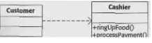
Dependency is the weakest relationship between objects. An object depends on an object if it has a shortterm relationship with the object. During this shortlived rela tionship, the dependent object may call methods on the other object to obtain services or configure the object. Real life is full of dependency relationships. We depend on the cashier at the grocery store to sell us food, but we do not have a longterm relationship with that person. In the UML, dependency is represented by a dashed line with an arrow pointing to the depended upon class.
Dependency relationships in objectoriented systems follow a few common pat terns. An object may create an object as part of a method, ask it to perform some func tion, and then forget about it. An object may create an object as part of a method, configure it, and pass the object to the method caller as a return value. An object may receive an object as a parameter to a method, use it or modify it, then forget about it when the method ends.
Figure 1.3 shows a dependency relationship between the Customer class and the Cashier class. This relationship reads as: "Each Customer object depends on Cashier objects," Changes to interface of the Cashier class may affect the Customer class.
Association
An association is a longterm relationship between objects, hi an association, an object keeps a reference to another object and can call the object's methods, as it needs them. Real life is replete with association relationships. Consider people with their automo biles. As long as they remember where they left their car, the car will let them in and take them to their destination. In the UML, association is represented by a solid line between the two classes.
hi some cases an object may instantiate another object and keep a reference to it for future use. An object may also receive an object as a parameter to a configuration method and keep a reference to the object.
Figure 1.4 shows an association relationship between the Person class and the Car class. The relationship is read as: "Every Person object is associated with an unspeci fied number of Car objects," and "every Car object is associated with an unspecified number of Person objects." It may help to think of this as a "knowsabouta" relation ship, as in "each Person object knows about some Car objects."
Introduction to Modeling Java with the UML 9
Figure 1.4 Sample association relationship.
Aggregation
An aggregation relationship indicates that an object is part of a greater whole. The con tained object may participate in more than one aggregation relationship, and exists independently of the whole. For example, a software developer may be part of two project teams and continues to function even if both teams dissolve. Figure 1.5 shows this aggregation relationship.
In the UML, aggregation is indicated by decorating an association line with a hollow diamond next to the "whole" class. The relationship is read as: "Each ProjectTeam object has some SoftwareDeveloper objects," and "each SoftwareDeveloper object may belong to one or more ProjectTeam objects."
Composition
A composition relationship indicates that an object is owned by a greater whole. The contained object may not participate in more than one composition relationship and cannot exist independently of the whole. The part is created as part of the creation of the whole, and is destroyed when the whole is destroyed. In the UML, composition is indicated by decorating an association with a solid diamond next to the "whole" class. Consider a small gear deep in the oily bowels of an internal combustion engine. It is inextricably part of the engine. It is not worth the cost of removal when the engine finally expires, and it is not accessible for replacement. Figure 1.6 shows this composi tion relationship. The relationship is read as: "Each Engine object always contains a SmallGear object," and "Each SmallGear object always belongs to a single Engine object."
Figure 1.5 Sample aggregation relationship.
10 Enterprise Java with UML
It may be difficult to remember which relationship is aggregation and which is composition. I offer a simple and somewhat silly mnemonic device for aggregation. Aggregation sounds a lot like congregation, as in members of a church. People may exist before joining a church. People may belong to more than one church, or they may change churches. Likewise, people continue to exist after leaving the church or after the church disbands or merges with another church. As for composition, well, it is the other one. Sorry.
Navigability
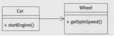
Relationships between objects are often onesided. For instance, in any car that I can afford, the Car object controls the Wheel objects, but the Wheel objects are unable to control the Car. Figure 1.7 shows an association relationship between the Car class and the Wheel class. The arrow pointing to the Wheel class indicates that the Car may send messages to the Wheel but that the Wheel cannot send messages to the Car. This means that a Car object may call the getSpinSpeed method on its Wheel objects and that the Wheel object may return a value from that method; but the Wheel does not have a ref erence to the Car object, so it cannot call the startEngine method.
According to the UML specification, an association line with no arrows can have one of two meanings. Developers on a project may agree that the absence of arrows means that the association is not navigable. Alternatively, developers on a project may agree that the absence of arrows means that the association is bidirectional.
Since there is no reason to have an association that is not navigable, the first inter pretation of an association with no arrows generally means that the navigability has not been determined. In this case, an arrow on each side of the line indicates bidirec tional navigability.
Developers on a project may agree that a tine with no arrows represents bidirec tional navigability. In this case, the doublearrow notation is never used and there is no way to indicate an unspecified or notnavigable association.
For this book, I use double arrows to indicate bidirectional navigability. I prefer this option because it allows me to defer consideration of the navigability of an association
Multiplicity
One object may have an association with a single object, with a certain number of objects, or with an unlimited number of objects. Figure 1.8 shows several relationships
Introduction to Modeling lava with the UML 11
Figure 1.8 Sample associations with multiplicity.
with the multiplicity determined. In the UML, the multiplicity describes the object that it is next to. So, an Engine object may have many SmallGear objects, but each Small Gear object belongs to exactly one Engine object. Each Car object is associated with one or more Person objects, and each Person object may be associated with several Car objects. Also, each Car object has exactly one Engine object, arid different Car objects never share an Engine object.
There is no default multiplicity. The absence of a multiplicity for an association indicates that the multiplicity has not been determined.
Interface
An interface defines a set of related behavior, but does not specify the actual implemen tation for the behavior. To be more specific, each interface completely specifies the sig nature of one or more methods, complete with parameters and return type. An interface captures an abstraction, without addressing any implementation details.
A class realizes an interface by implementing each method in the interface. The interface defines a set of behavior. The class makes it real.
Interfaces provide flexibility when specifying the relationship between objects. Rather than specifying that each instance of a class has a relationship with an instance of a specific class, we can specify that each instance of a class has a relationship with an instance of some class that realizes a particular interface. As we will see throughout this book, creative use of this feature provides an amazing amount of flexibility and extensibility.
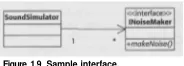
For instance, a game might contain a sound simulator object that is responsible for collecting and playing the sounds that emanate from various objects in a virtual world. Each SoundSimulator object is associated with zero or more objects whose classes real ize the INoiseMaker interface. From the Sound Simulator's perspective, the specific type of noisemaker is completely irrelevant. Figure 1.9 shows this relationship.
12 Enterprise Java with UML
Polymorphism
Polymorphism, according to my dictionary, means having more than one form. In objectoriented circles, polymorphism refers to multiple implementations of a single abstraction. Abstractions are captured in classes and in interfaces. So, we can get poly morphism by having more than one class inherit from a base class. Each class could simply override the default implementation provided by the base class. We can also get polymorphism by having more than one class realize an interface. Each class must pro
To continue our sound simulator example for polymorphism through inter faces, consider two classes that make noise, Trumpet and Tiger. Both implement the makeNoise method and realize the INoiseMaker interface. Each SoundSimulator object is associated with some objects whose classes realize INoiseMaker. The sound simulator does not need to know the specific class for each object. Instead, the sound simulator just asks the object to make some noise. Figure 1.10 shows the two classes that realize the INoiseMaker interface and the relationship between SoundSimulator and INoiseMaker.
Multiple implementations of an abstraction can also be achieved by having more than one subclass override the default implementation provided by the base class. Figure 1.11 shows an alternative approach in which each SoundSimulator object is associated with some objects that instantiate SimulationElement or a subclass of SimulationElement. As before, the SoundSimulator knows that the object on the other end of the association implements the makeNoise method, but does not know what sound to expect.
Polymorphism has two very significant benefits. First, polymorphism allows unlim ited flexibility within a running system. Different implementations of an abstraction can be mixed and matched to achieve very interesting affects. The second benefit is longterm extensibility for the system. As long as the abstraction is unchanged, new implementations can be introduced without affecting the code that depends on an interface. For example, adding a new class that realizes INoiseMaker does not affect the SoundSimulator class in any way.
Introduction to Modeling Java with the UML 13
Figure 1.11 Polymorphism through inheritance.
Modeling
Software Systems
with
the UML
UML enables developers to build a single coherent model that describes a software system from several perspectives. This combination of internal consistency and dis tinct views means that a variety of participants can use the same model and speak the same language throughout the development process. Granted, some participants will only use part of the model, but they can still follow the overall structure of the model.The Customer's Perspective
Most customers are relatively disinterested in technology. They are far more interested in the value that the system provides for them, that is, how it increases their produc tivity and makes their lives easier. Developers should gather requirements from the customer's perspective, considering how the customer will interact with the system to obtain value. This allows the customer to review and validate the requirements from a very natural perspective, his or her own. The customers can also measure development progress from an individual perspective.
UML provides several mechanisms for documenting system requirements from the user's perspective. They are the use case diagram, a text description for each use case, and an activity diagram for each use case.
14 Enterprise Java with UML
• The text description of each use case describes the use case, including the details of the interactions between the user and the system.
• An activity diagram is a visual description of the interactions between the system and the user for a use case.
Together, these diagrams help the customers and developers to fully understand the system problem from the customer's perspective.
The Developer's Perspective
Developers must first understand the problem, then the solution, from their own per spective. Objectoriented systems force developers to describe a system in terms of objects that cooperate to provide functionality to the users, so objectoriented develop ers focus on the objects that populate the system and the classes that define the objects. UML provides several mechanisms for documenting a system from the developer's perspective: class diagrams, state chart diagrams, package diagrams, sequence dia grams, and collaboration diagrams.
• A class diagram defines and constrains a group of objects in detail. It shows the state, behavior, and relationships with other objects that are mandated for each object that instantiates the class.
• A state chart describes the statedependent behavior for a class. Specifically, it describes how an object responds to different requests depending on the object's internal configuration.
• A package diagram describes how different parts of a system depend on one another based on the relationships between objects that reside in different parts of the system.
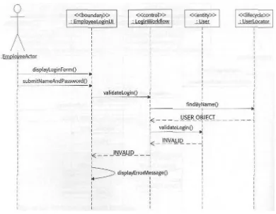
• A sequence diagram shows how objects interact with one another to provide func tionality. A sequence diagram clearly indicates the order of the interaction; it is less useful for determining the relationships between objects.
" A collaboration diagram also shows how objects interact with one another to pro vide functionality. Collaboration diagrams provide a counterpoint to sequence diagrams by clearly revealing the relationships between objects. However, they are less useful for determining the sequence of interactions.
Modeling Process
Introduction 1° Modeling lava with the UHL 15
Requirements Gathering
When gathering requirements, developers seek to understand the problem from the customer's perspective, without concern for technology or system design. This ensures that the developers are focused on the correct problem. While no system is immune to requirements change or "scope creep," adopting this perspective can prevent misun derstandings and dramatically reduce the severity of requirements changes.
In this process, developers create use case diagrams, text use case descriptions, and activity diagrams. I introduce requirements gathering in Chapter 2, "Gathering Requirements with UML." In Chapter 3, "Gathering Requirements for the Timecard Application," I begin gathering requirements for a sample application.
Analysis
In analysis, developers seek to understand the problem from their own perspective, still without concern for technology. Building on the understanding of the problem cre ated during requirements gathering, they discover the roles and responsibilities that must be filled in the system. This builds a solid foundation for technology selection and design of the system.
In the analysis process, developers create class diagrams, sequence diagrams, and collaboration diagrams. I introduce analysis in Chapter 4, "A Brief Introduction to ObjectOriented Analysis with the UML." In Chapter 5, "Analysis Model for the Time card Application," I demonstrate analysis in an example.
Technology Selection
During technology selection, developers categorize the system in terms of its techno logical requirements, then select the most appropriate technologies to fulfill these well defined needs. This orderly and disciplined approach to selecting technology trades a fairly large upfront effort for decreased risk over the life of the project.
In the technology selection process, developers use all of the existing documents and diagrams. They produce a highlevel summary of the technological requirements and a list of appropriate technologies for the system. No additional UML diagrams are produced.
Technology selection is covered in several chapters. In Chapter 6, "Describing the System for Technology Selection," I explain the process for describing the technology needs of a system, and reinforce these ideas by example. In Chapters 7 ("Evaluating Candidate Technologies for Boundary Classes") and 8 ("Evaluating Candidate Tech nologies for Control and Entity Classes"), I present different technologies and describe their suitability, before selecting appropriate technologies for the example system.
Architecture
16 Enterprise Java with UM1
shown as part of the architecture. Providing a highlevel view of the system and its component parts makes it possible for a large number of participants to evaluate the feasibility of the architecture. Also, during design and implementation, the architec ture serves as an invaluable highlevel guide to developers as they struggle to under stand the system as a whole.
Architecture builds on the cumulative understanding of the system as described in the use case model and in the technology selection. During architecture, developers produce primarily class diagrams and package diagrams.
I cover architecture in a single chapter: Chapter 9, "Software Architecture," explains the process and demonstrates it through the sample system.
Design and Implementation
In design, developers use all of the results from the previous steps as they create an intricate model of the objects that interact to provide the system's functionality. A detailed design provides the last chance to validate the solution before the extremely expensive and laborintensive implementation process begins. In about a day, a small group of developers who are familiar with UML and with the system can prepare for a thorough design review of a major subsystem. Compare this to the weeks that are required to read and understand the code for a major subsystem. A detailed design can be created, reviewed, and revised in a fraction of the time it takes to write the code.
Once the design is complete, it serves as a valuable foundation for implementation. Developers are free to focus their efforts on the details of the implementation tech nologies, without constantly worrying whether their efforts will fit within the larger system. As long as they follow the design, or reconcile any changes to the design with other developers, their work will not be wasted. I cover design and implementation in the remainder of the book: in Chapter 10, "Introduction to Design," I explain the process; I dedicate Chapters 11 ("Design for the Timecard Domain and Timecard Work flow"} and 12 {"Design for HTML Production") to designs for different parts of the sys tem.
The Next Step
Gathering Requirements
with UML
The first step to designing any enterprise application is to gather requirements for the system. A system's requirements consist of a document (or a collection of documents) that describes the functionality that the system provides. It is an agreement between the end user, the developer, and the system's sponsor as to what the system should and can do.
Requirements gathering is an interactive process whereby business analysts and developers gather system requirements by interacting with end users, domain experts, and other stakeholders. This highly iterative process is a combination of problem dis covery and consensus building that lays the foundation for the project's success.
In this chapter, I'll show you how the Unified Modeling Language (UML) can be used in a requirementsgathering process, I'll outline several classic paths that lead to poor requirements, then suggest ways that you can detect and avoid them.
18 Enterprise Java with UML
Are You Ready?
Before you can gather requirements, you need to do two things: 1. Create a clear vision of the system.
2. Determine who has the decisionmaking authority for the project.
The first step is to create a clear vision for the system. This vision is described in the vision document, a text document that presents an extremely highlevel explanation of the goals and scope of the system. The vision document can be in any format. In one company, the vision document may be two paragraphs transferred from the napkins that were handy during the dinner when the principals spawned the idea for the com pany. In another organization, it may be a formal document that presents an exhaustive
and fourcolor graphs on fancy paper. However it is presented, a successful vision doc ument describes the system, its goals, and how the organization benefits from it. The system goals are described at a fairly detailed level to give the developers and the cus tomers the flexibility to clarify the system vision. The document also highlights any known scope limitations.
The second step is to identify a sponsor or sponsors for the project. Gathering require ments without sponsors is painful at best and disastrous at worst, because they are the people who make final decisions regarding budget, features, and schedule. Ideally, the sponsors form a small decisive group that has the authority and vision needed to set tle disputes and to keep a clear focus for the project. In any system, compromises must be made. For example, some desired functionality might be deferred to a later release to meet the schedule. Different groups of users may have different needs and goals that pull the system in different directions. Without a clear decisionmaking authority, it is difficult to resolve issues and to keep them resolved. When decisions are made and remade in a frustrating cycle in an attempt to please everyone, developers often end up overcommitting themselves and, subsequently, end up disappointing everyone.
What Are Good Requirements?
Good requirements clearly and unambiguously state what the system does and for whom. They answer questions such as: Who uses the system? What value do users receive from their use of the system? These questions must be answered before con sidering technology selection, architecture, and design, otherwise, developers will be doomed to solve the wrong problems and be unable to make informed decisions about technology and architecture.
Requirements gathering involves five key steps: 1. Find the people who can help you understand the system.
2. Listen to these stakeholders and understand the system from their perspective. 3. Capture the way customers want to use the system, along with the value pro
Gathering Requirements with UML 19
4. Create a detailed description of the interactions between the system and the cus tomers and between the system and other external systems.
5. Refactor the detailed descriptions to maintain readability and accessibility. These steps are repeated until a solid consensus on what the system should do is reached. Notice that the goal is a solid consensus, not a 100 percent, perfect, consensus. Gathering requirements, like any creative and collaborative endeavor, never reaches a dear conclusion, as each iteration raises new subtleties and a new layer of details. Requirements must not become an end in themselves. Requirements are useful only as a form of communication and as a consensusbuilding process; they are not artistic works with intrinsic value. Each additional refinement of the requirements yields less and less value. At some point, the project must move on.
Find the Right People
In order to gather requirements, you must solicit input from people at different levels within the organization or user group. One group may understand the problem domain and strategic goals, but they may not actually use the system. Another group may not see the big picture, but may be intimately familiar with the daytoday activi ties. These people are the system's stakeholders, those who have a significant interest in the project's direction and success. Stakeholders include everyone from the end user to the development team to the senior managers who control the budget. It is up to you to establish a reasonable rapport with a wide variety of stakeholders, for they will pro vide you with the information you'll need to develop the requirements document.
Domain Experts
The domain experts are the strategic thinkers. They understand the organization and the system. They set the goals for the system as well as lend insight to their particular domain. These people are usually easy to identify, as they generally have a high profile and occupy nice offices. They may have advanced degrees, many years of experience in their field, and a senior position, such as CEO, vicepresident, or senior research fel low. Unfortunately, they also tend to be incredibly busy, talk too fast, and assume that everyone else knows and loves their field. To build the system that they need, you must understand them. To achieve that, you must make sure that they appreciate this simple truth and be confident that you will treat their time with care. Whenever possi ble, prepare by learning the relevant terminology and concepts inherent to their field before meeting with them, then baseline their expectations by explaining your limited background.
Subsequently, it is a good idea to verify your understanding of the conversations by paraphrasing them back to the source, preferably both verbally and in writing. Persis tence and humility are key ingredients to your success.
End Users
20 Enterprise Java with UML
remarkably, many organizations fail to solicit their input. Therefore, in some cases, you may need to push for access to a representative group of users. Sometimes the reluc tance of management to grant access to the end users is evidence of an honest effort to protect the end users' time. In other cases, institutional traditions and rigid hierarchies erect the barrier. A medical doctor, for example, may balk at the idea that a licensed practical nurse may have valuable insights into the actual use of a medical datatrack ing system. A manager with 20 years of experience may not realize that it has been 15 years since he or she actually did the work, and that a new hire may have a valuable perspective.
Be firm; excluding the actual users is not a viable option. Remember, developers must understand the daytoday pragmatics as well as the strategic value of the system.
•WARNING Never forget the end user.
Listen to the Stakeholders
Developers need insight and knowledge from the stakeholders. To facilitate this dia logue, you must temporarily suppress your own perspective and inclinations so you can hear these stakeholders. In most cases, domain experts and end users are not con cerned with cool technologies or objectoriented design principles; they want to know how they will benefit from the system. They are not interested in scarce technical resources or the risks of adopting new technology; they need a solid schedule that they can plan around. They are not interested in user interface design techniques; they just
Until you can clearly restate the customer's needs in your own words, do not plan the solution or consider the impact on the schedule. Above all, be positive, and try to think of the system in terms of the value that it provides to people. This is not an intu itive perspective for most developers, myself included. Our training and natural incli
natural tendency to consider the impact on our personal and professional lives. We must overcome this mindset—at least long enough to understand the needs of the people on the other side of the table.
It is important to remember that considering the other stakeholders' perspective does not mean committing to an impossible system or schedule. It means that devel opers are obligated to completely understand the requests and needs before contem plating feasibility and negotiating schedule.
Gathering requirements sets the stage for development and makesor breaksevery development team's relationship with the customer and domain experts.
Gathering Requirements with UML 21
transcribed recordings. Transcribed recordings are more accurate, but may make many people uncomfortable. In any case, a written dialogue that can be verified and built upon is an essential tool.
Develop Accessible Requirements
Requirements are useful if and only if people use them. If the user finds them turgid and/or incomprehensible, then they cannot tell you if you are specifying the right sys tem. If developers find them obtuse and irrelevant, then the actual system will radi cally deviate from the requirements. While even the best requirements document is unlikely to find itself on the New York Times bestseller list, a requirements document must be readable and accessible to a wide audience. Describing how the system is used at a high level is an important step toward this goal.
Requirements are useful if and only if people use them.
The highlevel diagrams within the use case model in UML provide an excellent mechanism for this purpose. Use case diagrams show discrete groups of system users as they interact with the system. There are three steps to creating a use case model.
1. Identify the groups of people who will use the system. 2. Determine how these groups of people will get value from the system. 3. Provide a simple and accessible view of the users and their use of the system.
The next sections take a closer look at each of these steps.
Find Actors
The first step to requirements gathering is to identify the distinct groups of people who will use the system. In UML, a distinct group is referred to as an actor. Other systems that use the system or are used by the system are also actors. So, an actor is a group of people or a system that is outside of the system and interacts with the system. To qual ify as an actor, the group must use the system in a different way.
It is important to note that differences in the real world may not be relevant within the system requirements. For example, managers often are considered a distinct group of people in the real world, whereas in many systems, they are not separate actors because they do not use the system in a manner that is different from the way an employee uses the system. Consider a simple timecard system, in which every employee enters his or her hours. A select few add valid charge codes. It is possible that some employees who add charge codes are managers, but that some are not. So man agers, in this case, do not need separate representation. Examples of reasonable actors from various domains will help clarify this distinction. The following groups are sepa rate actors in the given problem domain.