AX-2000/AX-2000 plus
Computer Interface Experiment set
CD-ROM information
Sourecode and Experiment program information in
INEXís Computer Interface CD-ROM
In CD-ROM is contained all sourcecode and demo software that compile and run with Visual BASIC V6.0 or higher (not test with VB.net). The sourcecodes are contained in
Parallel_port/Lab for Parallel port interface experiment Serial_port/Lab for Serial port interface experiment USB_port/Lab for USB port interface experiment
For demo execute files from sourcecode are contained in
Parallel_port/Software/Demo for Parallel port interface experiment Serial_port/Software/Demo for Serial port interface experiment
1. Software tools, drivers and control files
io.dll : Input/Output DLL for Parallel port (Parallel_port/Software/DLL) OCX file are contained in Parallel_port/Software/OCX.
Microchip HIDComm ActiveX setupex.exe : HIDComm setup file (USB_port/Software/Microchip HIDComm ActiveX)
hpcount.ocx is contained in USB_port/Software/OCX.
2. Parallel port experiment
Lab05 : 1-Phase stepper motor driver Lab06 : 2-Phase stepper motor driver
Lab07 : Half step mode stepper motor driver Lab08 : Drive 1-digit LED 7 segment
Lab09 : Drive LED 7 segment in multiplexed Lab10 : N/A
Lab11 : Port expansion via I2C bus
Lab12 : Analog interface via I2C bus
Lab13 : Output port expansion
Lab14 : Drive stepper motor with EX-09 Lab15 : Parallel port versus DS1621
3. Serial port experiment
Lab01 : Simple transmit serial data Lab02 : Building PCís timer control Lab03 : Reading logic to serial port
Lab04 : Receiving data with UTX8100 controller Lab05 : Receiving data from UART IN
Lab06 : Simple stepper motor controller Lab07 : Serial port drives relay
Lab08 : Receiving data and error verification Lab09 : Port expansion via I2C bus
Lab10 : Analog interface via I2C bus
Lab11 : Output port expansion
4. USB port experiment
Lab01 : Connect U-Board with HIDComm control Lab02 : PORTOUT experiment - transmit data to output Lab03 : PORTIN experiment - get data from input Lab04 : PORTIN experiment with Report ID0
Lab05 : Simple USB-based stepper motor controller Lab06 : Simple USB-based relay controller
Lbb07 : Analog interface with USB port Lab08 : Output port expansion for USB
(C) Innovative Experiment Co.,Ltd.
Parallel port interface board
P-board
Features :
l
In-built Buffer Circuit for all pins on port
l
On-board I
2C bus converter circuit
l
Polarity protection circuit
l Extension connector for DATA BUS, P-BUS,
CONTROL and STATUS For connecting
EX-series board
Packing List
l P-board
l Documentation
l CX-25 custom parallel port cable x 1
l IDC-20 cable x 1
Figure-1
Schematic of P-Board Parallel port interface board
IC001 7805 K001 DC 9-12V D001-D004 1N4001x4 C001 220/16V C002 0.1/50V C003 10/50 +5V C004 0.1/50 9 8 7 6 5 4 3 2 D7 D6 D5 D4 D3 D2 D1 D0 Q7 Q6 Q5 Q4 Q3 Q2 Q1 Q0 11 12 13 14 15 16 17 181 10 19
+5V 20 R001 220 LED001 POWER +5V R002 R004 3k3 10k R003 2k7 Q001 BC547 +5V R005 10k R007 3k3 R006 2k7 Q002 BC547 +5V SDA SCL S001 I2C SELECT (DIP SW-3) 2 3 4 5 14 6 7 8 9 10 11 12 13 1 17 16 15 18 19 20 21 22 23 24 25 D0 D2 D4 D6 D1 D7 D5 +5V D3 2 3 4 5 D0 D1 D2 D3 Q0 Q1 Q2 Q3 18 17 16 15
1 10 19
+5V 20 15 14 13 12 11 Q3 Q4 Q5 Q6 Q7 D3 D4 D5 D6 D7 5 6 7 8 9
1 10 19
Board description
The P-Board will be interface with the computer parallel port directly and has a buffer circuit to prevent the parallel port signal from error. This board provides 3 ports to transfer signal of parallel port.
1. Data port has 8 signal pins, and is called D0-D7. It is output port only. All signal are connected directly to DATA BUS connector. Their pin are assigned in UIC-10 pin standard (It is INEXís custom standard pin) and combined the signal into P-BUS. It contains all signal of parallel port pin.
2. Control port has 4 signal pins, and is called C0 to C3. C0, C1 and C3 is an invert logic pin. It is an output port only same Data port. Their pin are assigned in UIC-10 pin standard but use only 4 pins and combined the signal into P-BUS. It contains all signal of parallel port pin.
Addition Control port pin are used to I2C bus signal pin. C1 is config to SCL (Serial clock), C0 is config to SDA (Serial data output) and S7 (from Status port) is config to Input SDA (Serial data input). In using I2C bus signal, selected
by 3-points DIP switch.
3. Status port has 5 signal pins, and is called S3 to S7. Their pin are assigned in UIC-10 pin standard but use only 5 pins and combined the signal into P-BUS. It contains all signal of parallel port pin.
Addition a Status port pin S7 is used to I2C bus signal pin. It is config to Input SDA (Serial data input). In using I2C bus signal, selected by 3-points
DIP switch.
P-Board need +9V to +12V 500mA external DC power supply. Apply the supply voltage via DC jack. P-board has +5V regulator circuit. +5V regulated supply voltage is used for all circuit and some extension board interfaced via P-BUS ,
Figure-3
Show detail of INPOUT.BAS file
Figure-2
INPOUT.BAS launching
Step by step of simple parallel port interfacing
Normally in Visual BASIC programming, you do not prepare an OUT instruction. Add INPOUT32.BAS file into the current Visual BASIC project. The step is :
(1) Copy io.dll file from the bundled CD-ROM into the SYSTEM directory in Windows.
(2) Enter Project menu, select Add File for add INPOUT32.BAS file into
the Project. At Project window will appear INPOUT32.BAS file. See the figure-2
(3) Point to INPOUT32.BAS file. Use View Code command to see the
detail of INPOUT32.BAS file. See the figure-3
(4) INPOUT32.BAS file wil prepare INP and OUT instruction for Visual
Sample experiment-1
Data port sending value
with OUT instruction of Visual BASIC via P-Board
Material :
1. P-Board Parallel port Interface board x 1
2. EX-01 board x 1
3. Computer that available a parallel port, install Windows (98SE/ME/XP) and Visual BASIC V5.0 or higher
4. IDC-10 cable x 1
Procedure
1.1 Connect P-board with PCís parallel port and connect P-board with EX-01 by IDC-10 cable at DATA BUS connector. See figure-2
1.2 Open Visual BASIC.
1.3 Enter Project menu. Select Add File to add INPOUT32.BAS file (contain in bundle
CD-ROM of P-board) into Project. At Project window will appear INPOUT32.BAS file.
1.4 Place 2 Command Buttons into Form1 following figure-3.
1.5 Double click at
Command1
to enter View Code menu. Write the code belowfor
Command1_Click
eventPrivate Sub Command1_Click() Out &H378, &HFF
End Sub
Figure-3
Placing Command Button in
Visual BASIC
6. Double click at
Command2
and write the sourcecode forCommand2_Click
event below :
Private Sub Command2_Click() Out &H378, 0
End Sub
7. Apply voltage for P-Board
8. Run the program. Click
Command1
button. Observe the result at LED on EX-01board.
8-LEDs on EX-01 board turn on.
9. Click
Command2
button. Observe the result at LED on EX-01 board.8-LEDs on EX-01 board turn off
10. If program done not correct, check the parallel port address normally is 378H. Click My Computer and right click to select Property and select to Device Manager. The window in figure-4 will appear. Select Printer Port and click Property button and select to Resource tab. The window in figure-5 will appear. In this window will show the parallel port address the using. First number is DATA port address (0378). If user use different must change.
Figure-4
Device Manager window for
checking the hardware
Figure-5
Resource window of Parallel
Figure-6
Warning message of Inpout32.dll file not founding.
11. If the warning dialogue box in figure-6 appeares, it means that the user has not copied the Inpout32.dll fiile into SYSTEM folder of Windows.
12. If all is OK, change the value to send to EX-01 such as OUT &H378,&H55.
The LED will turn on and off swap. Because 55H value is 01010101 in binary.
Sample experiment-2
Control port sending value
with OUT instruction of Visual BASIC via P-Board
Material :
1. P-Board Parallel port Interface board x 1
2. EX-01 board x 1
3. Computer that available a parallel port, install Windows (98SE/ME/XP) and Visual BASIC V5.0 or higher
4. IDC-10 cable x 1
Procedure
2.1 Connect P-board with PCís parallel port and connect P-board with EX-01 by IDC-10 cable at DATA BUS connector. See figure-2
2.2 User can use program from experment-1. Edit Command1_Click to
Private Sub Command1_Click() Out &H37A, &HF4
End Sub
2.3 Edit Command2_Click to :
Private Sub Command1_Click() Out &H37A, &HB
End Sub
2.4 Run the program. Try to click the Command1 and Command2 button. Observe the operation.
Command2 button is pressed
All LED on EX-01 board turn-off. Because C0, C1 and C3 is an invert bit.
Command1 button is pressed.
LED on EX-01 board will turn-on only 4 positions. This is because Control port of parallel port has only 4-bits.
Figure-8
Placing Command button
Sample experiment-3
Status port reading value
with INP instruction of Visual BASIC via P-Board
Material :
1. P-Board Parallel port Interface board x 1
2. EX-01 board x 1
3. Computer that available a parallel port, install Windows (98SE/ME/XP) and Visual BASIC V5.0 or higher
4. IDC-10 cable x 1
Figure-7
Interface P-Board with EX-03
board
Procedure
3.1 Connect P-board with PCís parallel port and connect P-board with EX-03 at DIP switch side by IDC-10 cable at DATA BUS connector. See figure-7
3.2 Open Visual BASIC.
3.3 Build form, place Command button and Textbox following figure-8. The Text1 box would be to display switch data reading.
3.4 Add Inpout32.dll file into the program for using INP and OUT instruction.
3.5 Write the code below for Command1
Text1.Text = Inp(&H379)
3.6 Run the test program. Change the DIP switch value and see the result operation at Text1 box.
Figure-10
Change Interval
value in Timer1 to select
speed of program response.
Figure-9
Add timer for continuous
operation.
3.7 Reading the value by Text1.Text = Inp(&H379) command, it cause the value difficult to understand. The suitable value format is Hexadecimal. Edit program by adding Hex$ command as :
Text1.Text = Hex$(Inp(&H379))
3.8 However the reading value will still contain the unused bit which includes S2,S1 and S0 bit. It causes each reading to be incorrect. Try editing the program again. Add Logic instruction to solve this error. The edit program is :
Text1.Text = Hex$(Inp(&H379) And &HF8 )
3.9 From editing this program in step 3.8, value in S2, S1 and S0 bit is ì0î. Because AND operation all bit with ì0î value. Then F8 value in binary format is 11111000. Now the value in Text1 box is real switch data.
3.10 However the result from step 3.9 still has some error. S7 bit value must invert. Then add program below to fix this error :
Text1.Text = Hex$(Inp(&H379) And &HF8 Xor &H80)
3.11 In reading value, user must click Command1 button every reading. Add some program below to automatic reading. It use Timer. See figure-9
Private Sub Timer1_Timer()
Text1.Text = Hex$(Inp(&H379) And &HF8 Xor &H80) End Sub
3.12 Change the Interval value of Timer1 in Property to 500, see figure-10.
(C) Innovative Experiment Co.,Ltd.
Features :
l Interface with RS-232 serial port
l On-board RS-232 driver
lUART circuit function by custom
controller ; UTX8100
l Selectable baud rate and data
format by jumpers
l LED display of status and errors
l On-board I2C bus converter circuit
l Extension connector for DATA BUS, UART IN, UART OUT, SHIFT OUT and S-BUS For connecting EX-series board
S-Board V2.0
Serial port Interface Board
Circuit description
S-Board V2.0 board is computer serial port interface experiment board. The complete shcematic diagram shows in the figure 1. Serial port signal level from computer is following in RS-232 standard. They are ±3V to ±12V. S-board has 2 RS-232 transceiver ICs ; MAX232 for convert the level to TTL level. It helps interfacing with another device more suitable.
S-BUS connector
All serial port signals that via MAX232 ICs are sent to buffer IC ; 74HC541 for current driver and protect the computerís port from error. All buffered serial port signal are connected to S-BUS connector.
SERIAL OUTPUT connector
1 6 S -B oa rd V 2 .0 S er ia l p or t i n ter fa ce b oa
rd
Figure 1
S-Board V2.0 Serial port interfsace board schematic diagram
CTS 12 9 11 10 7 14 8 13 3 1 5 4 16 +5V 6 15 IC2 MAX232 C8 10/16V C7 10/16V C6 10/16V 12 11 10 7 14 13 3 1 5 4 15 IC3 MAX232 C12 10/16V C11 10/16V IC4 74HC541 R xD T xD D T R DSR DCD RTS DTR TxD RTS IC1 7805 K1 DC 9-12V D1-D4 1N4001x4 C1 220/25V C2 0.1/50V C3 47/16V +5V C4 0.1/50V R4 10k R2 10k R3 10k Q1 BC547 R5 10k R7 10k R6 4k7 Q2 BC547 1 2 3 4 5 9 8 7 6 +5V SDA SCL K6 I2C BUS (RJ11-4) S1 I2C SELECT (DIP SW-3) 5 8 4 13 17 14 18 20 12 15 3 16 7 6 2 DTR TxD RTS +5V Q0 Q1 Q2 Q3 Q4 Q5 Q6 Q7 +5V 20 CTS RxD DCD DSR +5V CTS RxD DSR DCD DTR TxD CTS RxD RTS DCD DSR +5V K3 SERIAL OUTPUT K5 S- BUS K4 SERIAL INPUT C13 0.1/50V +5V D0 +5V D2 D4 D6 D1 D3 D5 D7 9 8 7 6 5 4 3 2 D0 D1 D2 D3 D4 D5 D6 D7 D0 D1 D2 D3 D4 D5 D6 D7 D0 D1 D2 D3 D4 D5 D6 D7 +5V 20 D0 +5V D2 D4 D6 D1 D3 D5 D7 9 8 7 6 5 4 3 2 17 11 12 13 14 15 16 18 D0 D1 D2 D3 D4 D5 D6 D7 D0 D1 D2 D3 D4 D5 D6 D7 Q0 Q1 Q2 Q3 Q4 Q5 Q6 Q7 Parity Even Odd None PI 0 1 1
O / E
1 0 N/A Parity bit selection
39 38 37 36 35 34 33 32 TxOut RxD1 REQ 10 11 13 40 31 9 RST C14 2u2/50V JP2 Parity Bit, Stop bit SELECTION JP1 BAUD RATE SELECTION 1 FRAME ERROR 16 20 Parity Error DL R1 1k LED1 POWER K2 RS-232 FEMALE (FROM PC) IC5 S-BOARD UART TRANSCEIVER C15 0.1/50V C16 0.1/50V IC6 74HC573 K6 UART OUT K7 UART IN IC7 74HC541 +5V +5V +5V 11 9 26 27 1 10 11 1 10 19 OUT RD 1 10 19 PI O/E SB 4 3 2 Stop bit 1 2 SB 0 1 Stop bit selection
Length 8 bits 7 bits DL 0 1 Data Length selection
BAUD3 BAUD1 5 6 7BAUD2 +5V 9 8 +5V +5V +5V RPACK1 10k*4 +5V RPACK2 10k*8 RPACK3 10k*8 RPACK4 220k*8 RxD2 12 BD3 BD2 BD1 Baudrate selection BD3 BD2 BD1 Baudrate
0 0 0 57600 0 0 1 28800 0 1 0 19200 0 1 1 14400 1 0 0 9600 1 0 1 4800 1 1 0 2400 1 1 1 1200
SERIAL INPUT connector
Output signals of serial port include DCD, CTS, RxD and DSR. All signals are connected to SERIAL INPUT connector for receiving the external digital input signal.
I
2C cus jack
S-Board V2.0 board provides another extension bus. It is called I2C bus. The
I2C bus signal includes SCL and SDA. But all serial port signal are not bi-directional. Then must use 3 psignal to generate I2C bus signal
For SDA signal use RTS for transmitting and DCD for receiving. For SCL will use DTR signal to drive clock via transistor Q2
All signal of I2C bus include +5V and Ground are assigned to I2C bus jack in 6P4C modular jack.
UART circuit
For serial communication experiment completely S-Board V2.0 board provides a UART circuit. The heart of this circuit is UTX8100 UART custom controller. Its function similar popular UART chip. UTX8100 can interface in asynchronous serial data communication. The signal pin is TxD and RxD.
TxD signal will send the serial data to UTX8100 via RxD1 and RxD2 pin. UTX8100 will convert to 8-bit parallel data otu to D0 to D7 pin. All output sigal will pass to Latch driver 74HC573 and out to UART OUT connector for interface external output devices.
RxD signal will receive the serial data from TxOut of UTX8100 when trig with logic ë0í from DTR signal at REQ pin of UTX8100. The input data will get from D0 to D7 pin. They are latched from UART IN connector. Data in from UART IN will buffer via 74HC541. UTX8100 will convert 8-bit parallel data input to serial data and send to RxD.
UTX8100 can select baudrate 8 steps as : 1200, 2400, 4800, 9600, 14400, 19200, 28800 and 57600 bit per second by JP1 jumper that connected to BAUD1-BAUD3 pin of UTX8100
Except baudrate setting, UTX8100 can set data bit, parity checkinh and set stop bit by selected jumper. In case detect the error, UTX8100 will inform by error output pin ; Parity Error (PE) and Frame Error (FE). All error output pin will out logic ‘0’. If connected the display circuit active low, will see the operation.
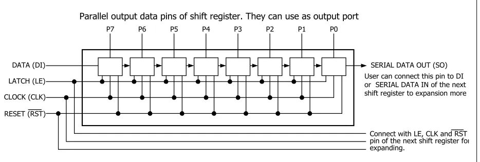
SHIFTOUT connector
S-Board V2.0 can expand the output port with synchronous data comminucation via SHIFT OUT. It includes SHIFT CLK and SHIFT DATA signal from UTX8100 controller. Both signal are sent to SHIFTOUT connector in name CLK (clock) and D0 (serial data). LE signal or Latch enable receive signal from the serial portís RTS signal. Last, RESET (RST) is SHIFT RST of UTX8100. The suitable expansion board for this connector is EX-09 board. Experimenters can expand output ports 8 to 64 bit from 4 signal and 4 EX-09 boards.
Sample experiment -1
Serial to Parallel data conversion
Material :
1. S-Board V2.0 Serial port Interface board x 1
2. EX-01 board x 1
3. Computer that available a parallel port, install Windows (98SE/ME/XP) and Visual BASIC V5.0 or higher
4. IDC-10 cable x 1
Procedure
Define serial data protocol between compuerís serial port and UART controller on S-Board V2.0 to 57,600 baud, 8-bit data, no parity and a stop bit.
1.1 Connect IDC-10 cable from UART OUT connector on S-Board to DATA BUS1 connector of EX-01 board.
1.2 Set baudrate jumpers on S-Board to select 57600. By BD1, BD2, BD3 as ì0î
1.3 Set PI, SB jumper as ì0î to select no parity and one stop bit.
1.4 Set DL jumper as ì0î to select 8-bit length.
1.6 Write program for Form_Load event to define data communication format as :
Private Sub Form_Load() MSComm1.CommPort = 1
MSComm1.Settings = “57600,n,8,1” MSComm1.PortOpen = True
End Sub
1.7 Write program for cmdOut_Click event as :
Private Sub cmdOut_Click()
MSComm1.Output = Chr(Val(“&H” & txtOut.Text) Mod 256) End Sub
The txtOut data format is hexadecimal but data that sent via MSComm.
Output must as character. Then convert the data to decimal in range 0 to 255 and
use Chr() function to convert to character.
Figure P1
Shows the UART out experiment program. It used to receive
Sample experiment -2
Parallel to Serial data conversion
Material :
1. S-Board V2.0 Serial port Interface board x 1
2. EX-03 board x 1
3. Computer that available a parallel port, install Windows (98SE/ME/XP) and Visual BASIC V5.0 or higher
4. IDC-10 cable x 1
Procedure
2.1 Connect IDC-10 cable from UARTIN connector on S-Board to DATA BUS of push-button switch on EX-03 board.
2.2 Set baudrate jumpers on S-Board to select 57600. By BD1, BD2, BD3 as ì0î
2.3 Set PI, SB jumper as ì0î to select no parity and one stop bit.
2.4 Set DL jumper as ì0î to select 8-bit length.
2.5 Open Visual BASIC. Build form and edit control following the figure P2
2.6 Write program for Form_Load to define data communication format as :
Private Sub Form_Load()MSComm1.CommPort = 1
MSComm1.Settings = “57600,n,8,1” MSComm1.PortOpen = True
MSComm1.DTREnable = False End Sub
Figure P2
Shows the UART in experiment program. It used to receive data
2.7 Write the delay routine as :
Private Sub Delay() Dim a As Single a = Timer + 0.01 Do While a > Timer DoEvents
Loop End Sub
2.8 Write program for cmdIn_Click as :
Private Sub cmdIn_Click() Dim tmp As String
MSComm1.DTREnable = True Delay
MSComm1.DTREnable = False Delay
If MSComm1.InBufferCount > 0 Then tmp = MSComm1.Input
txtIn.Text = Hex(Asc(tmp)) End If
End Sub
Receiving data of UART on S-Board must send signal to REQ pin of UTX8100 before. REQ pin will connect with DTR signal from serial port. Because the modern computers speed are very fast, it cause the UART chip may be cannot detect data in time. The delay routine will be very important. Program will poll for receive data at RxD pin by verify serial port buffer. If data is stored in buffer, program will
exit the loop and read buffer data to shows at txtIn box. If require to read data
(C) Innovative Experiment Co.,Ltd.
Features :
l Interface with USB port
l Support USB V1.0/1.1
l Powered by external or USB port (selection by jumper settings)
l Extension connector for PORTOUT, PORTIN and SHIFT
OUT For connecting EX-series board
l 8-Bit A/D circuit 5 channels (2 on-board and 3 for external voltages)
U-Board
USB port Interface Board
Circuit description
U-Board schematic diagram is shown in the figure 1. The main component is Microchipís USB pre-programmed microcontroller ; PIC16C745. This chip can conntect to USB port directly. In this schematic connect USB port pin series with resistors for current limited protection. Jumper JP1 POWER SUPPLY is used to select the power supply for U-Board from USB port or external If not drive the exrernal devide over 100mA, experimenters can use power supply +5V from USB port. If require more current, must use external power supply
U-BOARD USB1.0/1.1 INTERFACE BOARD Q0 Q1 Q2 Q3 Q4 Q5 Q6 Q7 +5V 20 +5V D0 +5V D2 D4 D6 D1 D3 D5 D7 9 8 7 6 5 4 3 2 D0 D1 D2 D3 D4 D5 D6 D7 D0 D1 D2 D3 D4 D5 D6 D7 D0 D1 D2 D3 D4 D5 D6 D7 +5V 20 D0 +5V D2 D4 D6 D1 D3 D5 D7 9 8 7 6 5 4 3 2 17 11 12 13 14 15 16 18 D0 D1 D2 D3 D4 D5 D6 D7 D0 D1 D2 D3 D4 D5 D6 D7 Q0 Q1 Q2 Q3 Q4 Q5 Q6 Q7 21 22 23 24 25 26 27 28 20 1 RST READY 6 19 LED1 READY R2 1k IC1 U-BOARD USB 1.0/1.1 INTERFACE FIRMWARE VID : 0x04D8
PID: 0xFFFF VER: 0x0100 C1 0.1/50V IC2 74HC573 K2 PORTOUT (EP1OUT) K3 PORTIN (EP1IN) IC3 74HC541 18 1 10 11 1 10 19 RD +5V D -D + 15 16 +5V RPACK1 10k*8 RPACK2 220k*8 12 13 14 15 16 17 18 19 17 LE CLK +5V DO LE RST K4 SHIFTOUT (EP1OUT) R1 10k CERAMIC RESONATOR 6MHz 10 9 X1 X2 12 SHF_LE 11 SHF_CLK 13 SHF_DO R3 10k R4 47k TR1 BC547 V USB 14 USB SPEED R5 1k5 +5V (*FULL) LOW DC.IN POWER SUPPLY BUS +5V R8 1k LED2 POWER CH.0 CH.1 +5V CH.0 2 CH.1 3 CH.2 4 CH.4 7 CH.3 5 CH.2 GND CH.3 CH.4 K5 A/D INPUT K1 USB PORT 5V. DC.IN 8 GND VCC VR1 10k VR2 10k C2 0.1/50V IC4 7805 K6 EXTERNAL DC. INPUT D1-D4 1N4001x4 C3 220/16V C4 0.1/50V C5 10/16 C6 0.1/50 5V. DC.IN * FULL SPEED RESERVED FOR FUTURE
USB MICROCHIP PIC18F2x50 ONLY
POLYSWITCH RUSB075 3 2 1 4 R6-R7 27
5 CH. 8 BIT A/D (EP2IN/OUT)
C7 47/16V
USB microcontroller has 5-ch. 8-bit analog to digital converter module. In this U-Board connect 2 of variable resistor for on-board variable voltage source and connect 3 terminal blocks for receiving external analog voltage.
U-Board is config to low speed HID class USB device. It cause cannot connect more U-board on the bus.
Preparation
(1) Install U-Board driver
(2) Install HIDcomm control
(3) Write the application program by Visual BASIC or another for interface with U-Board via HIDcomm control.
The important of this experiment is How to Windows know U-Board. The main linker is U-Board driver and HIDcomm
The step from here is very important. Experimenters must
do becareful.
Install U-Board driver
U-Board is config to HID (Human Interface Device) type then can use HID driver within Windows for connection. The install step is :
(1) Select U-boardís power supply to USB port.
(2) Connect USB cable between U-Board and USB port.
(4) Select to Display a list of all the drivers in a specific location.... Click Next button.
(5) Select USB Human Interface Device. Click Next button.
(7) Click Finish button. Installation is complete.
For Windows ME : The first time connection of U-Board will see the dialoque box infrom HID USB device detected following the figure below. After that syytem will install driver automaticcally and not appear the dialog box from step (1)
After driver installation complete, next step is making the application software ti interface U-Board. In U-Board programming, suggess to use API function. The API function is internal function of HID. Normally API programming will be very complex and require more programming skill. Microchip help developers by make the custom control to support.This control is called HIDComm. U-Boardís experimental program use this control in same.
HIDComm installation
(1) Run Microchip HIDComm ActiveX setupex.exe file for installation. This file will be contained in INEXís Computer interface CD-ROM. The installation window will appear.
Sample experiment-1
Interface U-Board with USB by HIDComm
Material :
1. U-Board USB port Interface board with USB cable x 1
2. Computer that available a parallel port, install Windows (98SE/ME/XP) and Visual BASIC V5.0 or higher
Concept :
U-board data transfer protocol
The figure P1-1 shows the software operation model of U-Board. U-Board is designed as HID class USB device. The Interface descriptor will use HID desicriptor to work with Endpoint descriptor. The operation format as :
l Transfer data 2 byte/packet. First byte is Report ID. Second byte is data.
Device Descriptor Config Descriptor Interface Descriptor Endpoint Descriptor HID Descriptor Report Descriptor EP0 IN / OUT
(Control Pipe 00) 8 byte EP1OUT (Pipe 01)
2 byte
EP1IN (Pipe 81) 2 byte EP2OUT (Pipe 02)
2 byte EP2IN (Pipe 82)
2 byte
0
1 PORTOUT 2 A/D Ch.
1 PORTIN 2 A/D Value
0 1 2
SHIFTBUS Latch & Report ID.1 Report ID.1 Report ID.2
2 A/D Ch.
2 A/D Value
Send Report 2 byte Receive Report 2 byte 0 1 PORTOUT 2 A/D Ch.
1 PORTIN 2 A/D Value
0 1 2
SHIFTBUS Latch & Report ID.1 Report ID.1 Report ID.2 Revision 2 Operational Model (Rev.2) (Rev.2) 3 0 1 2 Report ID.1 Report ID.2 SHIFTBUS Latch & Report ID.1
3 0 1 2 Report ID.1 Report ID.2 SHIFTBUS Latch & Report ID.1
l After receive data from computer, U-Board will collect Report ID of receiving data for prepare to send same Report ID back to computer when request.
l Cannot select Report ID in transmittion data to computer. This is limitation
of USB1.0
l Transfering data with any port are defined by Report ID as :
Report ID 0 Define the Report ID of transmittion to computer. There is 3 values as :
“0” Set Report ID of transmit data as 1 and latch data to
SHIFT OUT port on U-Board
ì 1 î Set Report ID of transmit data as 1
“2” Set Report ID of transmit data as 2
Report ID 1 Receive data from computer and pass to PortOut and read Port In data for sending back to computer.
Report ID 2 Receive data for select A/D input and send the conversion result.
l After receive data 1 packet, must delay at least 71 millisecond for U-Board initial operation before send data to computer.
Using HIDComm control with U-Board
U-Board connection
Must connect HIDComm with U-Board before transfer data. Experimenters can use Browse function to select the USB device. The sampl;e code shows below :
Private Sub cmdSelectDevice_Click() HIDComm.Browse
HIDComm.Connect End Sub
Another method, define the properties of HIDComm in the program to match with USB device in the program. Connect properties has 6 items as :
HIDComm.MatchManufacturer = “Innovative Experiment” HIDComm.MatchProduct = “U-Board USB1.0/1.1 Interface” HIDComm.MatchSerial = 0
HIDComm event
All HIDComm events can indicate the interface status. It devided 2 groups as
1. Connection status
ConnectFailure
ConnectSuccess
Disconnected
2. Transfer status
ReadFailure
ReadSuccess
WriteFailure
WriteSuccess
Procedure :
1. Connect U-Board with USB port
2. Place some control following the figure P1-2
3. Write the code for any event as :
Private Sub cmdConnect_Click()
HIDComm.MatchManufacturer = “Innovative Experiment” HIDComm.MatchProduct = “U-Board USB1.0/1.1 Interface” HIDComm.MatchSerial = 0
HIDComm.MatchPID = 4095 HIDComm.MatchVID = 1240 HIDComm.MatchVersion = 256 HIDComm.Connect
End Sub
Private Sub cmdDisconnect_Click() HIDComm.Disconnect
End Sub
Private Sub HIDComm_ConnectFailure(ByVal Status As Long) MsgBox “HIDComm_ConnectFailure”
End Sub
Private Sub HIDComm_ConnectSuccess(ByVal Status As Long) MsgBox “HIDComm_ConnectSuccess”
End Sub
Private Sub HIDComm_Disconnected(ByVal Status As Long) MsgBox “HIDComm_Disconnected”
End Sub
In running this probram, program window (figure P1-2) will appear. Click Connect button, The dialog box (figure P1-3) of connection between U-Board and HICComm will appear.
Full sourcecode can see in LAB01.VBP file in USB_port/Lab/Lab01 folder within INEXís Computer Interface CD-ROM.
Sample experiment - 2
PORTOUT experiment
Material :
1. U-Board USB port Interface board with USB cable x 1
2. EX-01 board x 1
3. Computer that available a parallel port, install Windows (98SE/ME/XP) and Visual BASIC V5.0 or higher
4. IDC-10 cable x 1
Concept :
PORTOUT of U-Board use ReportID 1 for interfacing. This component can send data each 2 bytes. The first byte is Report ID that HIDComm control willl transmit aitomatically. The second byte is data that outs to PORTOUT connector.
Procedure :
2.1 Connect EX-01 with PORTOUT connector of U-Board.
2.2 From program in experiment -1, add TextBox and CommandButtonfor transmitting data to U-Board following the figure P2-1
2.3 Write program for cmdWrite_Click event as :
Private Sub cmdWrite_Click() Dim Buffer(0) As Byte
Buffer(0) = CByte(“&H” & txtOut.Text)
HIDComm.ReportID = 1 ‘ Send Report ID
HIDComm.WriteTo Buffer, 1 ‘ Transmit data to U-Board End Sub
Sending data through HIDComm control use WriteTo command. Parameter
of this command must as Array variable and following data byte. From the experiment code, data sending is width 1 byte thus declare one Array variable
start at 0. After that get data from txtOut to convert to numerical and store at
Experiment result : When program is running, initialize interface between U-Board with HIDComm happen before. Experimenters can observe from the interface complete dialog box that appear. Experimenters must click to accept before. After that the experimental program window will appear. Put data into PortOut box and click Write button. That data will send to EX-01 board via PORTOUT connector. LED at EX-01 will show value same at Port Out box in the pogram window.
16-ch. LED display board
(C) Innovative Experiment Co.,Ltd.
Features :
l
Two 8-bit LED monitor
l
On-board buffer and driver
circuit
l
Available connector for
P-board, S-Board and U-Board
EX-01
R108 D0 D2 D4 D6 D1 D7 D5 +5V D3 1 19 +5V 20 10 9 8 7 6 5 4 3 2 R101 D 7 D 6 D 5 D 4 D 3 D 2 D 1 D 0 Q 7 Q 6 Q 5 Q 4 Q 3 Q 2 Q 1 Q 0 11 12 13 14 15 16 17 18D0 D1 D2 D3 D4 D5 D6 D7 IC101 74HC541 C101 0.1/50V R101-R108 220 x8 LED101 LED108 R116 1 19 +5V 20 10 9 8 7 6 5 4 3 2 R109 D 7 D 6 D 5 D 4 D 3 D 2 D 1 D 0 Q 7 Q 6 Q 5 Q 4 Q 3 Q 2 Q 1 Q 0 11 12 13 14 15 16 17 18
D0 D1 D2 D3 D4 D5 D6 D7
IC102 74HC541 C102 0.1/50V R109-R116 220 x8 LED109 LED116 D0 D2 D4 D6 D1 D7 D5 +5V D3 K102
DATA BUS #1
(UIC-10)
K103
DATA BUS #2
(UIC-10)
K101
P-BUS
(IDC-20)
C0 C1 C2 C3 C3 C2 C1 C0
EX-01
LED display board
Sample experiment-1
Data port sending value
with OUT command of Visual BASIC via P-Board
Material :
1. P-Board Parallel port Interface board x 1
2. EX-01 board x 1
3. Computer that available a parallel port, install Windows (98SE/ME/XP) and Visual BASIC V5.0 or higher
4. IDC-10 cable x 1
Procedure
1. Connect P-board with PCís parallel port and connect P-board with EX-01 by IDC-10 cable at DATA BUS connector. See figure-2
2. Open Visual BASIC.
3. Enter Project menu. Select Add File to add INPOUT32.BAS file (contain in bundle CD-ROM of P-board) into Project. At Project window will appear INPOUT32.BAS file.
4. Place 2 Command Buttons into Form1 following figure 3.
Figure-3
Placing Command Button in
Visual BASIC
Figure-2
P-board interface with EX-01
Figure-4
Device Manager window for
checking the hardware
Figure-5
Resource window of Parallel
port for report the parallel port
5. Double click at
Command1
to enter View Code menu. Write the code below forCommand1_Click
eventPrivate Sub Command1_Click() Out &H378, &HFF
End Sub
6. Double click at
Command2
and write the sourcecode forCommand2_Click
event below :
Private Sub Command2_Click() Out &H378, 0
End Sub
7. Apply voltage for P-Board
8. Run the program. Click
Command1
button. Observe the result at LED on EX-01 board.8-LEDs on EX-01 board turn on.
Figure-6
Warning message of Inpout32.dll file not founding.
10. If program done not correct, check the parallel port address normally is 378H. Click My Computer and right click to select Property and select to Device Manager. The window in figure-4 will appear. Select Printer Port and click Property button and select to Resource tab. The window in figure-5 will appear. In this window will show the parallel port address the using. First number is DATA port address (0378). If user use different must change.
11. If the warning dialogue box in figure-6 is appeared, it means user do not copy Inpout32.dll fiile into SYSTEM folder of Windows.
12. If all OK, change the value to send to EX-01 such as OUT &H378,&H55.
Sample experiment-2
Control port sending value
with OUT command of Visual BASIC via P-Board
Material :
1. P-Board Parallel port Interface board x 1
2. EX-01 board x 1
3. Computer that available a parallel port, install Windows (98SE/ME/XP) and Visual BASIC V5.0 or higher
4. IDC-10 cable x 1
Procedure
1. Connect P-board with PCís parallel port and connect P-board with EX-01 by IDC-10 cable at DATA BUS connector. See figure-2
2. Use can use program from experment-1. Edit Command1_Click to
Private Sub Command1_Click() Out &H37A, &HF4
End Sub
3. Edit Command2_Click to :
Private Sub Command1_Click() Out &H37A, &HB
End Sub
4. Run the program. Try to click Command1 and Command2 button. Observe the operation.
Command2 button is pressed
All LED on EX-01 board turn-off. Because C0, C1 and C3 is invert bit.
Command1 button is pressed.
LED on EX-01 board will turn-on only 4 positions. Becaise Control port of parallel port has only 4-bits.
LED 7 segment display board
(C) Innovative Experiment Co.,Ltd.
EX-02
1 10 19 +5V 20 D0 D2 D4 D6 D1 D7 D5 +5V D3 C0 C1 C3 C2 D7 D6 D5 D4 D3 D2 D1 D0 Q7 Q6 Q5 Q4 Q3 Q2 Q1 Q0 11 12 13 14 15 16 17 18 9 8 7 6 5 4 3 2
DSP204 DSP203 DSP202 DSP201 DSP201-DSP204 : LED 7 SEGMENTS COMMON CATHODE
b c d e f g dp a R201-R208
100x8 common common common common C201 0.1/50V IC201 74HC541 K201 P-BUS
Figure-1
EX-02 schematic
Features :
l 4-Digit LED 7 segment display
l On-board buffer and driver circuit
l Active logic ìHIGHî for segment and
logic ìLOWî for common control
l Connect with P-Board via P-BUS connector
Circuit description
Schematic diagram of EX-02 board show in figure 1. 4 digits of LED 7-segments will connect in multiplex. All same segments will connect together and connect to buffer ICs, 74HC541. Input of 74HC541 are connected to DATA BUS connector that interface with P-Board. The reason is all data pins of parallel port cannot drive LED directly.
LED 7-segments display is common cathode type. It need logic ë1í to drive each segment pin via limited-current resistor. Each common pin of LED are connected to the parallel portís control pin, C0 to C3. User can control LED each digit via this control line.
Sample experiment-1
Drive LED display single digit
Material :
1. P-Board Parallel port Interface board x 1
2. EX-02 board x 1
3. Computer that available a parallel port, install Windows (98SE/ME/XP) and Visual BASIC V5.0 or higher
4. IDC-20 cable x 1
Procedure
1.1 Make the dispaly data table of LED 7 segments with arrey by wrote the VB code below :
Dim Number(0 To 9) As Integer Private Sub Form_Load()
Number(0) = &H3F Number(1) = &H6 Number(2) = &H5B Number(3) = &H4F Number(4) = &H66 Number(5) = &H6D Number(6) = &H7D Number(7) = &H7 Number(8) = &H7F Number(9) = &H6F End Sub
From the code, must reserve the memory space with ‘Number’
variable. It is decleaed by DIM command at head of the code.
1.2 Target is after click at Command1 button, LED at right digit will show numerical value and increase value every clicking. The sample code can show below :
Dim Index As Integer
Private Sub Command1_Click() If Index < 10 Then
Out &H378, Number(Index) Index = Index + 1
Else Index = 0 End If
Out &H37A, &H5 End Sub
This code declare ‘Index’ variable to access the data table, The Index
value is in range 0 to 9. After that use Out command to send the data to LED’s
However in LED configuration at right digit is connected to C0 pin. This pin will invert logic then send logic “1” to this pin instead. The common control data is 5 in decimal or 0101 in binary to because must turn-off another digit.
1.3 Connect P-Board with EX-02 board by IDC-20 cable via P-BUS connector.
1.4 Apply the supply voltage to both board. Ru the program from step 1.2. Observe the operation at EX-02 board.
1.5 Edit the experiment code to change the display digit by send the value as :
2nd digit (count from the right) display data is &H6
3rd digit display data is &H0
4th digit (The left digit) display data is &HC
Turn-off all digit data is &H4
Turn-on all digit data is &HB
Sample experiment-2
Drive LED display in multiplexed mode
Material :
1. P-Board Parallel port Interface board x 1
2. EX-02 board x 1
3. Computer that available a parallel port, install Windows (98SE/ME/XP) and Visual BASIC V5.0 or higher
4. IDC-20 cable x 1
Procedure
2.1 Write the experiment code below :
Private Sub Command3_Click() Exits = False
Do
Out &H378, Number(1) Out &H37A, &H5
Call delay
Out &H378, Number(2) Out &H37A, &H6
Call delay
Out &H378, Number(3) Out &H37A, &H0
Call delay
Out &H378, Number(4) Out &H37A, &HC
Call delay Out &H37A, &H4
Loop Until Exits = True End Sub
This code will diaplay number 1,2,3 and 4 in each digit from the left. After send data to display in each digit must delay to latch the display before send the data to next digit. Human eye cannot see the changing in each digit. Then user will see all LED can work in same time.
For delay routine, user xan adjust the dealy time from scroll bar. Because computer speed in each will be not equal. The sample VB code of delay routine can see below :
Sub delay()
For i = 1 To HScroll1.Value DoEvents
Next i End Sub
For i = 1 To Hscroll1.Value
to
For I = 1 To “TARGET VALUE”
After the program run complete in one cycle, loop program will scan the LED again until Exits varaible’s value is True. It will be true by pressing Exit button to exit the program.
2.2 Connect P-Board with EX-02 board by IDC-20 cable via P-BUS connector.
2.3 Apply the supply voltage to both board. Run the program from step 1.2. Observe the operation at EX-02 board.
2.4 Try to edit the delay routine to find the best displaying as good as possible.
Computer clock via Parallel port
Procedure
This experiment will be demonstration about digital clock. Use EX-02 board as display board. The timebase will get time value from computerís system clock.
2.5 Make textbox Text1 for display time value. Use timer2 for convert time value to LED data display. Write the experiment code below :
Private Sub Timer2_Timer()
Text1.Text = Format(Now, “hh:mm:ss”) Index1 = Asc(Right(Text1.Text, 1)) - &H30 Index2 = Asc(Mid(Text1.Text, 7, 1)) - &H30 Index3 = Asc(Mid(Text1.Text, 5, 1)) - &H30 Index4 = Asc(Mid(Text1.Text, 4, 1)) - &H30 End Sub
The first line is defining the current time value to Text1. The format is Hour,
Nimute and Second.
Second line is getting only the right letter of Text1. It is first digit of Second
value. Get this value by Right command. After that convert this data to ASCII (&H30-&H39 means 0 to 9) For correct number value must subtract the ASCII value
with &H30. Index1 variable will be 0 to 9 number. User will get this data to open the
data table to send to LED 7-segment.
In 3rd to 5th line of code are similar operation. Each program line operation will be different about data position. It will get the tens of Second, Minute and
Hour data to store in Index1 to Index4 variable.
Displaying method is similar the experiment-1 but not define the arrey address
directly, user can use Index1 to Index4 value from calculation to access arrey
Private Sub Command3_Click() Exits = False
Do
Out &H378, Number(Index1) Out &H37A, &H5
Call delay
Out &H378, Number(Index2) Out &H37A, &H6
Call delay
Out &H378, Number(Index3) Out &H37A, &H0
Call delay
Out &H378, Number(Index4) Out &H37A, &HC
Call delay Out &H37A, &H4
Loop Until Exits = True End Sub
The changing of this upper code is putting the variable value into Number
arrey. In this sample code is get value of Hour, Minute and Second to display on LED. Experimenters can modify program to display only Hour and Minute by editing
the code of Timer2. Interval value of Timer2 is 100 to 1000 millisecond.
The program window is shown in the figure P2-1 and example program can see in the EX-09.VBP file (See detail in P-board CD-ROM)
3.2 Connect P-Board with EX-02 board by IDC-20 cable via P-BUS connector.
3.3 Apply the supply voltage to both board. Run the program from step 3.1 Observe the operation at EX-02 board.
Figure P2-1
Computer clock programs screen
(C) Innovative Experiment Co.,Ltd.
Features :
l
8-Ch. DIP switch with pull-up
l
8-Ch. push-button switch with
pull-up
l
Available connector
ìDATA
BUS
î
16-ch. Switch input board
EX-03
Figure-1
Schematic of EX-03 Switch input board
+5V
R301 10k*8
S301 D0 S302
D1 S303
D2 S304
D3
S305 D4 S306
D5 S307
D6 S308
D7
+5V S309
DIP SW.-8
D0 D2 D4 D6
D1
D7 D5 +5V
D3
D0 D2 D4 D6
D1
D7 D5 +5V
D3
R302 10k*8
K301
DATA BUS
(UIC-10)
K302
DATA BUS
(UIC-10)
EX-03
(C) Innovative Experiment Co.,Ltd.
Features :
l
Power uni-polar stepper motor
5-24V 1.5A (max)
l
Require external power supply
lGround isolated by opto-coupler
lConnect to P-Board & S-Board via
ìDATA BUSî connector
#8002005
Stepper motor driver board
EX-05
Circuit description
Schematic diagram of EX-05 board show in figure 1. Input signal from DATA BUS will drive infrared LED within opto-coupler IC501-IC504. Output of IC501-IC504 connected with transistor Q501-Q504 BD139 to drive motor. Opto-coupler can active after receive logic ì1î and drive transistor. The coil end will be connect to ground and that phase can active. Stepper motor will spin a step. If all input received the continuous signal, driver circuit will be active and drive motor to spin another step continuous. Experimenters can define the 4-bit input data to control a uni-polar stepper motor. The driving method has 3 method : Full step, Half step and Micro step.
The supply voltage of EX-05 board must separated from the supply source of P-Board . The level can change following motor rating. EX-05 board can use with the supply voltage exceed +30V 1A current.
R501 510 D0 D2 D1 +5V D3 K501 DATA BUS (UIC-10) +V IC501 4N25 1 2 5 4 R506 1k R505 1k Q501 BD139 D501 1N4001 R502 510 +V IC502 4N25 1 2 5 4 R508 1k R507 1k Q502 BD139 D502 1N4001 R503 510 +V IC503 4N25 1 2 5 4 R510 1k R509 1k Q503 BD139 D503 1N4001 R504 510 +V IC504 4N25 1 2 5 4 R512 1k R511 1k Q504 BD139 D504 1N4001 +V P1 P2 P3 P4 K502 STEPPER MOTOR EX-05
Stepper motor driver board
Sample experiment-1
1-Phase Stepper motor driving
Material :
1. P-Board Parallel port Interface board x 1
2. EX-05 board x 1
3. Computer that available a parallel port, install Windows (98SE/ME/XP) and Visual BASIC V5.0 or higher
4. +12V 2A external DC power supply fo EX-05 board x 1
5. Uni-polar Stepper motor 12V 100
:
7.5 degree/step x 16. IDC-10 cable x 1
Procedure
Input data for 1-Phase stepper motor driving has 2 groups. One are 1, 2, 4 and 8 for anti-clockwise direction. Another are 8, 4, 2 and 1 for clockwise direction. See the driving data in the table P-1
1.1 Make the Comand1 button and write the experiment code as :
Private Sub Command1_Click() Lefts = False
Rights = True Do
DoEvents Out &H378, 1
Call delay Out &H378, 2
Call delay Out &H378, 4
Call delay Out &H378, 8
Call delay
Loop Until Lefts = True End Sub
Step Phase-4 Phase-3 Phase-2 Phase-1
0
1 0 0 1
0
2 0 1 0
0
3 1 0 0
1
4 0 0 0
Table P1
Sequnce operation of stepper motors coil in 1-phase full step driving
(A) Step data in Left rotation (B) Step data in Right rotation
Step Phase-4 Phase-3 Phase-2 Phase-1
1
1 0 0 0
0
2 1 0 0
0
3 0 1 0
0
1.2 Interface P-Board with EX-05 board by IDC-10 cable via DATA BUS conector and connect the stepper motor to EX-05 board. Must check the correct phase before connection.
1.3 Apply the power supply to P-Board and EX-05 board.
1.4 Run the experiment program from step 1.1
1.5 Click Command1, program will be send values 1,2,4 and 8 in order to. Each data will be separated by delay routine. In same time, Do....Loop Until
command will check the Command2 status. Observe motor operation.
1.6 About Delay routine, have many techniques to make it. One is using timebase timer. The advantage of this technique is delay time still equal in all computer. But this techniques has limit of speed. It cause speed of program may be not enouh to run some condition. The minimum value is 0.01 second. Sample program in VB6 can show below :
Sub delay() Times = Timer Do
DoEvents
Loop Until Timer >= Times + 0.01 End Sub
This routine will verify value inTimer variable. This value is internal computer
timebase (Times) plus 0.01 in Second unit. If internal time is equal or more than
Times +0.01, program will be out of delay routine loop. Doevents command is
assist to run another routine such as can click Command2 button in delay loop.
1.6 Another delay routine can show in this step below. This code can increase the speed working but depend on each computer.
Sub delay()
For i = 1 To HScroll1.Value DoEvents
Next i End Sub
This routine useFor...Next command and Hscroll slide bar for adjust speed.
In case the loop has long time period and protect the program hang, must insert
Figure-P1
Stepper motor control program window
1.7 For the Right rotation, must make the Command2 button. See the code below :
Private Sub Command2_Click() Lefts = True
Rights = False Do
DoEvents Out &H378, 8
Call delay Out &H378, 4
Call delay Out &H378, 2
Call delay Out &H378, 1
Call delay
Loop Until Rights = True End Sub
Overall operation will be similar Left rotaion. Different is only rotate data.In this direction use value 8,4,2 and 1 instead. The window program can see in figure P1.
Sample experiment-2
2-Phase Stepper motor driving
Material :
1. P-Board Parallel port Interface board x 1
2. EX-05 board x 1
3. Computer that available a parallel port, install Windows (98SE/ME/XP) and Visual BASIC V5.0 or higher
4. +12V 2A external DC power supply fo EX-05 board x 1
5. Uni-polar Stepper motor 12V 100
:
7.5 degree/step x 16. IDC-10 cable x 1
Procedure
2.1 The 2-phase stepper motor drivng data format is shown in table P2 . Tha data value will be 9,3,6 and 12 (in decimal) for Left rotation and 12, 6, 3 and 9 for Right rotation. Edit the Visual BASIC code in Command1 and Command2 button from the simple experiment-1 as :
Dim i As Integer
Dim Lefts, Rights As Boolean Private Sub Command1_Click()
Lefts = False Rights = True Do
DoEvents Out &H378, 9
Call delay Out &H378, 3
Call delay Out &H378, 6
Call delay Out &H378, 12 Call delay
Loop Until Lefts = True End Sub
Step Phase-4 Phase-3 Phase-2 Phase-1
1
1 0 0 1
0
2 0 1 1
0
3 1 1 0
1
4 1 0 0
Step Phase-4 Phase-3 Phase-2 Phase-1
1
1 1 0 0
0
2 1 1 0
0
3 0 1 1
1
4 0 0 1
Private Sub Command2_Click() Lefts = True
Rights = False Do
DoEvents Out &H378, 12
Call delay Out &H378, 6
Call delay Out &H378, 3
Call delay Out &H378, 9
Call delay
Loop Until Rights = True End Sub
2.2 Interface P-Board with EX-05 board by IDC-10 cable via DATA BUS conector and connect the stepper motor to EX-05 board. Must check the correct phase before connection.
2.3 Apply the power supply to P-Board and EX-05 board.
2.4 Run the experiment program from step 2.1
2.5 Observe the stepper motor operation and compare with the experiment-1 (step 1.4)
The 2-phase full step technique can drive more torque but require more power 2 times.
Sample experiment-3
Half-step mode
Material :
1. P-Board Parallel port Interface board x 1
2. EX-05 board x 1
3. Computer that available a parallel port, install Windows (98SE/ME/XP) and Visual BASIC V5.0 or higher
4. +12V 2A external DC power supply fo EX-05 board x 1
5. Uni-polar Stepper motor 12V 100
:
7.5 degree/step x 16. IDC-10 cable x 1
Procedure
The half-step technique cause stepper motor driving more resolution 2 times than full step mode. Then it need data 8 value for cycle. See the sequence operation in Table P3. The data for Left rotation are 9, 1, 3, 2, 6, 4, 12 and 8. The Right rotation data are 8, 12, 4, 6, 2, 3, 1 and 9
3.1 Write the experiment code for Command1 and Commande2 button as :
Private Sub Command1_Click() Lefts = True
Rights = False Do
DoEvents Out &H378, 9
Call delay Out &H378, 1
Call delay Out &H378, 3
Call delay Out &H378, 2
Call delay Out &H378, 6
Call delay Out &H378, 4
Call delay Out &H378, 12 Call delay Out &H378, 8
Call delay Out &H378, 0
Private Sub Command2_Click() Lefts = False
Rights = True Do
DoEvents Out &H378, 8
Call delay Out &H378, 12 Call delay Out &H378, 4
Call delay Out &H378, 6
Call delay Out &H378, 2
Call delay Out &H378, 3
Call delay Out &H378, 1
Call delay Out &H378, 9
Call delay Out &H378, 0
Call delay
Loop Until Lefts = True End Sub
Step Phase-4 Phase-3 Phase-2 Phase-1
1
1 0 0 1
0
2 0 0 1
0
3 0 1 1
0
4 0 1 0
0
5 1 1 0
-6 1 0 0
1
7 1 0 0
1
8 0 0 0
Step Phase-4 Phase-3 Phase-2 Phase-1
1
1 0 0 0
1
2 1 0 0
0
3 1 0 0
0
4 1 1 0
0
5 0 1 0
0
6 0 1 1
0
7 0 0 1
1
8 0 0 1
Table P3
Sequnce operation of stepper motors coil in half-step mode
(A) Step data in Left rotation (B) Step data in Right rotation
3.2 Interface P-Board with EX-05 board by IDC-10 cable via DATA BUS conector and connect the stepper motor to EX-05 board. Must check the correct phase before connection.
3.3 Apply the power supply to P-Board and EX-05 board.
3.4 Run the experiment program from step 3.1
3.5 Observe the stepper motor operation and compare the result with the experiment-1 and 2
Stepper motor will rotate slower than experiment-1 and 2 but it rotate more resolution 2 times.
(C) Innovative Experiment Co.,Ltd.
EX-06A
7-ch. Relay driver board
Features :
l
Drive 12V relay 7 channels with LED status
l
Require +12V external power supply
l
Selection by jumper settings
NO C NC D0 D2 D4 D6 D1 D7 D5 +5V D3 1 2 3 4 5 6 7 16 15 14 13 12 11 10 8 9 D6 D5 D4 D3 D2 D1 D0 Q6 Q5 Q4 Q3 Q2 Q1 Q0 JP1 IC1 ULN2003 RY1
RELAY 12V K3-1 RELAY OUT #1 K1 ,)6)*75 (UIC-10) LED1 R1 1.8k NO C NC RY2
RELAY 12V K3-2 RELAY OUT #2 LED2 R2 1.8k NO C NC RY3
RELAY 12V K3-3 RELAY OUT #3
LED3 R3 1.8k NO C NC RY4
RELAY 12V K3-4 RELAY OUT #4
LED4 R4 1.8k NO C NC RY5
RELAY 12V K3-5 RELAY OUT #5
LED5 R5 1.8k NO C NC RY6
RELAY 12V K3-6 RELAY OUT #6
LED6 R6 1.8k NO C NC RY7
RELAY 12V K3-7 RELAY OUT #7
Circuit Description
EX-06A board provides 7 mechanical relays. Ther are drived by ULN2003 driver. The schematic diagram seein figure 1.
The heart of this board is ULN2003 IC. It has 7 inverter driver. All input are connected to JP1 to JP8 jumper. Experimenters can select by manual. Another end of jumpers are connected DATA BUS connector. Prepare for connect with P-Board, S-Board and U-Board.
The logic to activate is High. ULN2003 will be invert to Low at output. Current flow pass the coil. It causethe relay coil active. Relay contact will switch from NC to NO. LED at each relay will light.
(C) Innovative Experiment Co.,Ltd.
Features :
l Connect I2C BUS via modular jack
l Expanable 16-bit/board. up to 4
boards, 64-bit I/O
l Select address by jumper
lAvailable ìDATA BUSî connector for
P-board, S-Board and U-Board
EX-07
I
2
C-based I/O Expansion board
+5V 16 SDA SCL A0 A1 A2 1 2 3 9 7 6 5 4 15 14 IC801 PCF8574 ADDRESS SELECT A1 A2 A0
IC BUS CONNECTOR 10 11 12 P4 P3 P2 P1 P0 P5 P6 P7 8 +5V 16 SDA SCL A0 A1 A2 1 2 3 9 7 6 5 4 15 14 ADDRESS SELECT A1 A2 A0 10 11 12 P4 P3 P2 P1 P0 P5 P6 P7 8 R802 R-network 4.7k x8 R801 R-network 4.7k x8 EX-07
IC-BASED 16 Bit I/O BOARD +5V
+5V K801
K802
JP801 JP802 JP803
IC802 PCF8574
JP804 JP805 JP806
Circuit description
The figure 1 shows EX-07 board schematic. The heart of this board is PCF8574A, 8-bit input/output (I/O) expander for the two-line bidirectional bus (I2C) IC. The PCF8574A provides general-purpose remote I/O expansion for most microcontroller families via the I2C interface [serial clock (SCL), serial data (SDA)]. The device features an 8-bit quasi-bidirectional I/O port P0ñP7), including latched outputs with high-current drive capability for directly driving LEDs. Each quasi-bidirectional I/O can be used as an input or output without the use of a data-direction control signal. At power on, the I/Os are high. In this mode, only a current source to Vcc is active. An additional strong pullup to Vcc allows fast rising edges into heavily loaded outputs. This device turns on when an output is written high and is switched off by the negative edge of SCL. The I/Os should be high before being used as inputs.
EX-07 board has two PCF8574A. Then one board can support 16 I/O and can expand 4 boards 64 I/O. One board must select two different address by jumpers. One PCF8574A must set one address by A0-A2 jumpers.
I2C bus of EX-07 board use modular jack 6P4C pin type. Experimeters can conect direct to P-Board and S-Board.
I2C Interface
I2C communication with this device is initiated by a master sending a start condition,
a high-to-low transition on the SDA I/O while the SCL input is high. After the start condition, the device address byte is sent, most-significant bit (MSB) first, including the data direction bit (R/W). This device does not respond to the general call address. After receiving the valid address byte, this device responds with an acknowledge, a low on the SDA I/O during the high of the acknowledge-related clock pulse. The address inputs (A0ñA2) of the slave device must not be changed between the start and the stop conditions.
The data byte follows the address acknowledge. If the R/W bit is high, the data from this device are the values read from the P port. If the R/W bit is low, the data are from the master, to be output to the P port. The data byte is followed by an acknowledge sent from this device. If other data bytes are sent from the master, following the acknowledge, they are ignored by this device. Data are output only if complete bytes are received and acknowledged. The output data will be valid at time, after the low-to-high transition of SCL and during the clock cycle for the acknowledge.
Sample experiment
Expansion I/O port of Parallel port via I
2
C bus
Material :
1. P-Board Parallel port Interface board x 1
2. EX-07 board x 1
3. EX-01 board x 1
4. EX-03 board x 1
5. Computer that available a parallel port, install Windows (98SE/ME/XP) and Visual BASIC V5.0 or higher
6. I2C bus cable x 1
7. IDC-10 cable x 1
Procedure
Interface EX-07 board programming
1. Put jumpers to select address of PCF8574A #1 on EX-07 board to 000. Another one select 001 address.
2. Connect P-Board with EX-07 board by I2C cable and connect EX-01 board with IDC-10 cable following in figure P1.
3. Write the code to send data to output of PCF8574A for driving LED on EX-01 board as :
Private Sub Command1_Click() Sendout (&HAA)
End Sub
Private Sub Sendout(B As Integer)
Call I2CStart ‘Start
Call Send8BIT(&H70) ‘Send Address Word Call Ack ‘Acknowledge
Call Send8BIT(B) ‘Send Data Call Ack ‘Acknowledge Call I2CStop ‘Stop
End Sub
Private Sub I2CStart()
Private Sub I2CStop()
Out &H37A,Inp(&H37A) And &HFE ‘SDA=0 Out &H37A,Inp(&H37A) Or 2 ‘SCL=1 Out &H37A,Inp(&H37A) Or 1 ‘SDA=1 End Sub
Private Sub Send1()
Out &H37A,Inp(&H37A) Or 1 ‘SDA=1 Out &H37A,Inp(&H37A) Or 2 ‘SCL=1 Out &H37A,Inp(&H37A) And &HFD ‘SCL=0 End Sub
Private Sub send0()
Out &H37A,Inp(&H37A) And &HFE ‘SDA=0 Out &H37A,Inp(&H37A) Or 2 ‘SCL=1 Out &H37A,Inp(&H37A) And &HFD ‘SCL=0 End Sub
Private Sub Ack()
Out &H37A,Inp(&H37A) Or 1 ‘SDA=1 Out &H37A,Inp(&H37A) Or 2 ‘SCL=1 Out &H37A,Inp(&H37A) And &HFD ‘SCL=0 End Sub
The interface programís screen can show in figure P2.
Figure P1
Shows interfacing of
P-Board, EX-07 and EX-01 board
Figure P2
Shows the programs
screen of sending data to output
ofPCF8574A.
Reading input from I
2C bus device
Before read data from I2C bus, the first thing to do is set the bus to idle. The last bit (LSB) of address must set to ë1í. It means host request to read data from device.
In VB program writing for reading data 8 bit will be use DAT function to loops 8 times for reading data and compare the LSB bit of data. In using DAT function, it will return 8-bit data. The sample program can show below :
Private Function DAT() For I = 7 To 0 Step -1
Out &H37A, Inp(&H37A) Or 1 ‘SDA=1 Out &H37A, Inp(&H37A) Or 2 ‘SCL=1 If (Inp(&H379) And &H80) = &H80 Then ‘Read SDA DAT1 = 2 ^ I Or DAT1
End If
Out &H37A, Inp(&H37A) And &HFD ‘SCL=0 Next I
DAT = DAT1 ‘Data 8 Bit End Function
Reading input from EX-07 board
4. Except use 07 board for sending the output data, experimenters can use EX-07 to reading data. In this experiment will use EX-03 for input source. Add routine below to read the switch data by Timer1 :
Private Sub Timer1_Timer()
Call I2CStart ‘Start
Call Send8BIT(&H71) ‘Send Control Word Call Ack ‘Acknowledge
Text1.Text = Hex$(DAT) Call Ack
Call I2CStop End Sub
Reading data step are :
(1) Send START condition.
(2) Send PCF8574A address and define to read mode.
(3) Send Acknowledge condition.
(4) Read data by DAT function.
(5) Send Acknowledge following STOP condition.
5. Interfac P-Board, EX-07, EX-01 and EX-03 following figure P1.
6. Run the experiment code in step 4. The screen of this program is shown in figure P3.
Figure P3
I
2C bus reading data program screen
7. Select data input at push-button swithces on EX-03 board. Observe the result on programís screen at Text1.
Features :
l Connect I2C BUS via modular jack l8-bit A/D converter 4 ch. Input 0 to +5V.
l 8-bit D/A converter 1 channel
lExpanable 4 analog inputs and 1 analog output per board. Up to 8 boards, 32 analog inputs and 8 analog outputs.
l Select address by jumper
(C) Innovative Experiment Co.,Ltd.
EX-08
I
2
C-based ADC/DAC board
+5V 16 14 Vref SDA SCL 5 6 7 8 12 EXT Aout 1 2 3 4 15 AGND13 9 10 K803 ANALOG OUTPUT K804 ANALOG INPUT IC801 PCF8591 ADDRESS SELECT A1 A2 A0
I C BUS CONNECTOR Ain0 Ain1 Ain2 Ain3 A0 A1 A2 +5V JP804 JP805 JP806 JP807 VR801 V R8 0 2 V R8 0 3 C801 0.1/50V
JP801 JP802 JP803
VR801-VR804 10k x4
EX-08
I C-based ADC board
Circuit description
The figure 1 is EX-08 schematic. The main device is PCF8591 IC. The PCF8591 is a single-chip, single-supply low power 8-bit CMOS data acquisition device with four analog inputs, one analog output and a serial I2C-bus interface.
Three address pins A0, A1 and A2 are used for programming the hardware address, allowing the use of up to eight devices connected to the I2C-bus without additional hardware. Address, control and data to and from the device are transferred serially via the two-line bidirectional I2C-bus.
The functions of the device include analog input multiplexing, on-chip track and hold function, 8-bit analog-to-digital conversion and an 8-bit digital-to-analog conversion. The maximum conversion rate is given by the maximum speed of the I2C-bus.
Normally, if use one EX-08 board, suggess to set its address to 000. Interface with P-Board and S-Board, the EX-08 board use I2C bus modular jack same EX-07 board and can expand to 8 boards if set different address.
The input of EX-08 board can select 2 sources. One is from external via terminal blocks. Another is variable resistors on EX-08 board. Experimenters can select by jumpers JP704-JP707.
The analog output of EX-08 has only one channel per board. Output voltage range is 0 to +5V selected by software.
Sample experiment
Analog interface with Parallel port via I
2
C bus
Material :
1. P-Board Parallel port Interface board x 1
2. EX-08 board x 1
3. Computer that available a parallel port, install Windows (98SE/ME/XP) and Visual BASIC V5.0 or higher
4. 0-5V DC power supply 4 outputs or 4 of single output 0-5V DC power supply.
5. Digital multimeter with probe x 1
Procedure
Reading analog input from EX-08 continuous
Step interfacing of PCF8591 are :
(1) Send START condition.
(2) Send PCF8591 address; 000 (A0 to A2 connect to ground) and define to write mode (bit LSB clear to ë0í : R/W = 0).
(3) Wait for ACK condition from PCF8591.
(4) Send control data to PCF8591; 45H. It means Enable analog output, Set analog input to single mode, Reading continuous and Start to read ADC channel 1.
(5) Wait for ACK status from PCF8591.
(6) Send STOP condition.
(7) Send START condition.
(8) Send PCF8591 address; 000 again but set the LSB to ë1í (R/W = 1) for beginning read data from analog input.
(9) Wait for ACK status from PCF8591.
(10) Read input of ADC channel 1.
(11) Send MAck (Master Ack) condition to PCF8591
(12) Read input of ADC channel 2.
(13) Send MAck (Master Ack) condition to PCF8591
(14) Read input of ADC channel 3.
(15) Send MAck (Master Ack) condition to PCF8591
(16) Read input of ADC channel 4.
(17) Wait for ACK condition from PCF8591.
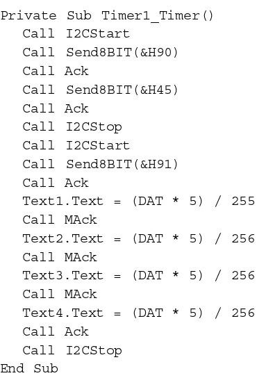
From all step above, can convert to VB code below :
‘ Read 4 analog input in continuous
Private Sub Timer1_Timer() Call I2CStart
Call Send8BIT(&H90) Call Ack
Call Send8BIT(&H45) Call Ack
Call I2CStop Call I2CStart
Call Send8BIT(&H91) Call Ack
Text1.Text = (DAT * 5) / 255 Call MAck
Text2.Text = (DAT * 5) / 256 Call MAck
Text3.Text = (DAT * 5) / 256 Call MAck
Text4.Text = (DAT * 5) / 256 Call Ack
Call I2CStop End Sub
MAck sub-routine is used to send Acknowledge condition from computer to
PCF8591. The detail of this routine can show below :
‘ MAck subroutine Private Sub MAck()
Out &H37A, Inp(&H37A) And &HFE ‘SDA=0
Out &H37A, Inp(&H37A) Or 2 ‘SCL=1
Out &H37A, Inp(&H37A) And &HFD ‘SCL=0
Out &H37A, Inp(&H37A) Or 1 ‘SDA=1
End Sub
About I2CStart, Send8BIT, Ack and I2CStop s