DEVELOPMENT OF THE BRICAN TD100 SMALL UAS AND PAYLOAD TRIALS
*B. Eggleston a, B.McLuckiea, W.R. Koski b, D. Bird c, C. Patterson c, D. Bohdanov e,H. Liu e, T. Mathewsa ,G. Gamagea
a Brican Automated Systems, 54 Van Kirk Drive, Brampton, ON, L7A 1C7, Canada, [email protected] (mcluckieb, gamageg, mathewst)@brican.com
b,LGL Environmental Research Associates, 22 Fisher Street, P.O.Box 280, King City, ON, L7B 1A6, Canada
Dept. of Natural Resource Sciences, McGill University, 21,111 Lakeshore Road, Ste-Anne-de-Bellevue, Quebec, H9X 3V9, Canada, (david.bird, charla.patterson)@mcgill.ca
e Institute for Aerospace Studies University of Toronto, 4925 Dufferin Street, Toronto, ON, M3H 5T6, Canada
[email protected], [email protected]
Commission VI, WG VI/4
KEY WORDS: UAS, BLOS, Multifuel, DSLR, Infrared, Georeferencing, Forest-fire, Wild-Life
ABSTRACT:
The Brican TD100 is a high performance, small UAS designed and made in Brampton Ontario Canada. The concept was defined in late 2009 and it is designed for a maximum weight of 25 kg which is now the accepted cut-off defining small civil UASs. A very clean tractor propeller layout is used with a lightweight composite structure and a high aspect ratio wing to obtain good range and endurance. The design features and performance of the initial electrically powered version are discussed and progress with developing a multifuel engine version is described. The system includes features enabling operation beyond line of sight (BLOS) and the proving missions are described. The vehicle has been used for aerial photography and low cost mapping using a professional grade Nikon DSLR camera. For forest fire research a FLIR A65 IR camera was used, while for georeferenced mapping a new Applanix AP20 system was calibrated with the Nikon camera. The sorties to be described include forest fire research, wildlife photography of bowhead whales in the Arctic and surveys of endangered caribou in a remote area of Labrador, with all these applications including the DSLR camera.
1. INTRODUCTION
The Brican TD100 is a high performance, fixed wing small UAS or RPAS designed and manufactured by a small company called Brican Automated Systems located in Brampton Ontario, Canada. The company’s main business creates customized robotic systems for improving manufacturing processes. The TD100 concept was defined in late 2009 and it was primarily targeted at the anticipated growth in future civil operations of UAS, as the military market was judged too mature to attempt a late entry. Six years later the civil market is only just emerging and applications are constrained by restrictions to line-of-sight operation until reliable sense and avoid technology is in place.
The TD100 vehicle was designed for a maximum weight of 25 kg which is now the cut-off defining small UASs in Canada and elsewhere. The wing span is about 5 metres and it has a high aspect ratio planform and custom designed airfoils to achieve long range and endurance. The external structure is a lightweight hollow shell using carbon skins and foam and it is designed to meet load cases appropriate to a CAR23 civil aircraft regulations. A tractor propeller layout is used which places the main payload bay under the wing. The payload bay is sized to have a weight and volume capability larger than others in its category giving versatility so that bulky sensors or multiple types can be carried simultaneously.
The initial “E” version of the vehicle is electrically powered
* Corresponding author
using high energy density lithium-polymer batteries, It has a usable duration of more than two hours and is very quiet. In order to extend the range and duration substantially. a version is in development using a multifuel I/C engine, the NW-44, propulsion. The vehicle and its systems are being tested and
documented to meet the “Best Practices” standards that have been adopted in Canada to assure safe and reliable operations of UASs.
The expectation is that such UASs will often replace manned fixed wing aircraft and also some rotary winged types that are used today for wildlife research, aerial survey work and for multiple purposes in a broad range of civilian applications including monitoring pipelines and powerlines, mapping, and resource exploration on both land and offshore. Potential government applications include border security and sovereignty patrols. UASs will displace observers from traditional aircraft vehicles which will have important safety benefits as the aviation record shows significant exposure to danger for test crews (Sasse, 2003). Additionally flight time limitations due to observer fatigue no longer become a concern, especially when computer assisted detection is integrated into data collection.
The company is now in the phase of demonstrating applications of the TD100, gaining operational experience and establishing the benefits in costs and data quality for future commercial work.
The International Archives of the Photogrammetry, Remote Sensing and Spatial Information Sciences, Volume XL-1/W4, 2015 International Conference on Unmanned Aerial Vehicles in Geomatics, 30 Aug–02 Sep 2015, Toronto, Canada
This contribution has been peer-reviewed.
The first part of this paper will focus on describing the technical features and performance of the vehicle and its operational support systems. The second part will recount some missions and the sensor payloads that have been carried during demonstrations of the vehicle. These have included high resolution photography of endangered wildlife including whales and caribou. Also they include the testing of an Applanix AP20 system that creates directly georeferenced maps and stereo images. In addition a FLIR A65 infrared camera has been used for detecting latent hot spots after forest fires subside.
2. TD100 DESIGN FEATURES
2.1 Layout and Electric Propulsion
Two main considerations dominated the TD100 configuration. The first goal was to achieve excellent range and duration capabilities which led to a very clean low drag exterior with a wing of gliderlike high aspect ratio (18:1) using in-house custom designed airfoils, Figure 1. The main wing airfoil was tested in a wind tunnel at UTIAS and the results validated the predicted lift and drag behavior obtained using the Drela XFOIL code (Drela, 1987) for low Reynolds number airfoils.
The low aerodynamic drag of the vehicle actually caused problems during landing as ground effects reduced drag further causing the vehicle to float and it became difficult to land precisely. As a solution the wing was modified to accept a split flap inset into the lower surface. When extended the flap increases both lift and drag substantially and descent angles increase to more than 10 degrees on the approach while stall speeds reduce about 20% which results in more precise and shorter landings becoming possible.
Figure 1: TD100E UAV in flight
The second goal was to have a large capacity main payload bay that would accommodate large payloads approaching sizes found in some Class 3 UASs. The main payload bay is about 38 cm long between bulkheads and it has a maximum width about 25 cm. The payload bay is located under the wing which means that changes in the payload’s fore and aft centre of gravity location or its weight do not cause large changes in the aircraft’s centre of gravity when fully loaded which alleviates potential balance problems. An internal arrangement of a layout used for forest fire research is given
in Figure 2 and shows the disposition of camera equipment in the main payload bay and other equipment in the vehicle.
Figure 2: Internal arrangement of equipment in forest fire research configuration
A tractor propeller layout is used and this arrangement leads to improved propeller efficiency and lower noise and vibration than pusher installations. The first version is electrically powered using an AXI 5345 brushless direct drive motor rated at 90 amps and 3400 watts maximum power. This allowed direct measurements of the power needed to fly the vehicle which enabled the vehicle drag and power requirements to be determined.
The early vehicles used COTS hobby grade lithium-polymer batteries in a 10s/4p arrangement but their duration was unsatisfactorily short. A change was made to an Amicell manufactured battery which has 40% greater energy density and provides 37 watt hours, giving about 2.3 hrs duration at search speeds depending on battery temperatures. Battery technology is advancing rapidly and lithium-sulphur types could provide a further 40% improvement in duration.
A two blade folding propeller is used with a diameter of 0.61 m and a pitch of 0.3 m which suits normal launch, climb and cruise operations. The propeller pitch limits maximum speed to about 140 km/hr as the pitch is too fine and only 50% of the available power is capable of being absorbed at that speed.
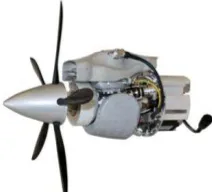
2.2 Multifuel Engined Version
In order to increase range and flight duration a version is under development using the NW-44 internal combustion engine that can run on various fuels from gasoline to diesel types, see Figure 3. The engine is currently being installed in the aircraft for testing during this summer. It is expected that the weight of the installed powerplant plus fuel for ten hours of flight will be about the same total as the present electric powerplant plus the main battery. This means the payload capability will remain the same in both the electric and multifuel versions. The engine also includes a 250 watt generator for supplying power to payloads and meeting other requirements.
2.3 Structure and Design Requirements
The exterior of the wing comprises two layers of Textreme spreadtow carbon with a thin layer of Divinycell foam inside overlaid with a layer of glass cloth. The materials are hand laid up with epoxy in machined molds made of a cast urethane material. The tapered spar caps in the wing are custom made from bonded layers of high strength unidirectional carbon material. The carbon airframe structure is very sturdy and lightweight and it weighs about 8 kg.
The design loads for the airframe of the vehicle are based on CAR23 civil aircraft standards for a utility aircraft as obtained using the Part23 Loads program (Miedlar, 1997). This sets a maximun normal g limit load of 4.4 for the manoeuvering cases. However the design cruise speed, Vc, selected is 99 kt which also requires meeting a gust limit load of 10.5 g so there is a considerable reserve of strength.
Special design cases were developed to reflect launch loads and hard landing events and also allowances were made for mishandling by careless operatives. A very robust airframe has resulted.
2.4 Guidance, Control and Communication Systems
When necessary the vehicle can be flown under direct pilot control using an independent R/C system with triple redundant receivers. The vehicle has 2.4 GHz and 900 MHz modems for command and control communication purposes with ranges about 10 and 20 km respectively.
The vehicle is usually flown using a Micropilot 2128g2 autopilot that can be preprogrammed with waypoints for the mission using a PC based system. The waypoints can also be modified BLOS using an Iridium satellite link. The programmed track and the actual flight path are monitored and displayed on a screen at the ground control station. The status of the critical guidance, control and propulsion systems are monitored by a safety system that adapts to the failure mode and performs an appropriate response including spiraling down, returning to base under autopilot control then holding, or a reversion to pilot control.
The payloads are controlled by an independent PC based interfacing with the displays for both systems.
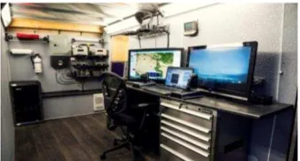
Figure 4 Interior of control cab
The flight controls use Volz military grade actuators. For redundancy the elevators are split with independent actuators on each half. Each aileron is independently actuated and there is one rudder actuator. The flaps have independent actuators on each side and they are equipped with clutches to prevent damage from snatching on obstacles. However in winter temperatures the bungee became unusable as the energy storage capability became greatly diminished. Subsequently a takeoff dolly was developed that was left behind after lift off. This arrangement sometimes had interesting issues with losing tracking on uneven surfaces.
The company has now developed a catapult launcher powered by compressed air. The vehicle sits on shoe attached to the fuselage underside that fits onto a launch trolley running along the edges of a square metal outer tube that encloses an internal tube with a drive piston and exhaust ports. The piston travels down the tube and pulls the trolley forward using a cable and pulley. The trolley motion is stopped at the end by a combination of hydraulic dampers, springs and internal compression of air in the tube.
The compressed air is supplied from an air tank that also supports an electrically driven compressor powered by a portable generator set. There are interlocks and safety systems in place on the valves and switches and the launch process can be either manual or fully automatic with the vehicle under autopilot control. The entire launch system can be mounted on a pickup truck as shown in Figure 5, or secured to the ground.
Figure 5 : Launcher System on a Truck
Thus far the vehicle has been landed under pilot control as the Micropilot autopilot does not have a proven autoland capability. The vehicle lands on its belly and if the ground surfaces are rough the bottom is covered with a protective plastic material.
Experiments have recently started using a Piccolo autopilot which has an autoland capability along with a 1cm DGPS system with an RTK beacon to achieve precision landings.
2.5 Summary of TD100E UAS Characteristics
The following three tables provide information about the The International Archives of the Photogrammetry, Remote Sensing and Spatial Information Sciences, Volume XL-1/W4, 2015
International Conference on Unmanned Aerial Vehicles in Geomatics, 30 Aug–02 Sep 2015, Toronto, Canada
This contribution has been peer-reviewed.
TD100E aircraft and its powerplant characteristics and the flight performance.
Table 6 TD100E aircraft specification
Table 7: TD100E propulsion system
Tables 8: Performance estimates for TD100E
2.6 Beyond Line of Sight Operation
Up to the present time UAS flights in civil airspace have been limited to visual line of sight (VLOS) operations except in special circumstances such as military test ranges. However for profitable commercial work fixed wing UASs will require BLOS over extended ranges. As a step towards developing a system enabling BLOS Brican has flown the TD100 equipped with an ADS-B beacon and monitored the flight progress BLOS. A Furano marine radar has also been adapted to suit UAV detection and it will be calibrated and tested later in 2015 year.
3. MISSIONS AND PAYLOADS TESTING
3.1 Locating Latent Hot Spots after Forest Fires
These tests were set up to detect simulated residual hot spots that can remain dangerous after a forest fire has apparently been extinguished (Bohdanov, 2013). The tests were conducted at the Burwash Fire Test facility of the OMNR. Ten hot spots were simulated using burning charcoal at 450oC in small open pans that were randomly placed in various types of cover. The TD100E vehicle was equipped with a FLIR A65 infra red camera with a 25 mm lens along with a custom made data storage unit. A professional quality full frame RGB camera the Nikon D3X with a 24 mp sensor was also carried to take still images and both are shown in Figure 2.
The TD100 was flown over the site at 150 m height above
ground giving an image coverage of 68 m by 54 m on the ground. The track spacing gave an overlap of 50% in both x and y, see Figure 9.
.
Figure 9: TD100 search pattern
The display from the A65 was monitored in real time for hot spots and as a first step the aircraft GPS was used for their locations. The resulting errors relative to the actual locations are given in table 10 and they show an average error of 45 m.
Table 10: Estimated errors in hot spot locations
Subsequently the IMU and the GPS data from the flight were curve fitted and interpolated to obtain the body angles in space
for each image so that the GPS locations could be corrected for attitude effects. The second data set in table 10 shows the errors estimated after such corrections were applied and the average error reduces to 3 m. One hot spot was missed in the survey as the data storage capacity available proved insufficient.
3.2 Photo-ID Quality Images of Bowhead Whales
The purpose of this sortie was to support LGL Limited environmental research associates (Koski, 2014 a) with the collection of high quality photos of bowhead whales that could be used for the identification of individual whales from their scars and blemishes. The test site was above the Arctic Circle near Igloolik, Nunavut. The whales were located at sea just beyond the edge of an ice shelf remaining during the spring breakup. Conditions were difficult because of heavy rainstorms the day before the study started and equipment and supplies had to be moved into position across the heavily ponded ice by sled and skidoo, Figure 11.
Aircraft Specification
Wing Span 4.98 m 195.9 in
Overall Length 2.00 m 78.8 in
Overall height 0.54 m 21.32 in
Fuselage Diameter 0.25 m 10.0 in
Empty Weight as R/C 16.2 kg 35.6 lb
MTOW 25.0 kg 55.0 lb
Propulsion System
Motor Model AXI 6345/16HD
Max Motor Current 90 amp
Max Motor Power 3400 watts
max RPM 7200
Battery Manufacturer Amicell
Battery Capacity 37 AHr
Battery Voltage 38 V
Prop Diameter and Pitch 0.61m/0.3 m
Performance Estimates at MTOW
Stall Speed Flaps Up 57 km/hr 31 kt
Stall Speed landing Flaps 46 km/hr 25 kt
Max Design Cruise Speed 184 km/hr 99 kt
Max Cruise Speed (pitch ltd) 148 km/hr 80 kt
Search Speed 83 km/hr 45 kt
Max Climb Rate 457 m/min 1400 fpm
Max Range 160 km 100 nm
Max Endurance 2.3 hr 2.3 hr
Locations From Corrected For
Figure 11 : In position at edge of ice shelf
Flights were limited to visual line of sight by the SFOC so two pilots and two control stations were needed, one set to launch from a gravel beach on the landward side of the ice shelf, Figure 12, then handing over control of the UAS to the second pilot positioned in a chase boat at sea. On return the vehicle was belly landed on the snow alongside the beach.
Figure 12 : Onshore pneumatic launch site
The TD100 carried a Nikon D800 DSLR camera with a 36 mp sensor and a 50 mm lens for high resolution RGB photography. The UAS flew at heights of 120 m to 180 m above sea level and the camera resolution at 120 m height was one pixel =1.2 cm. There were also two GoPro cameras fitted for forward and downwards viewing. Their resolution with a 127o field of view lens was 25 cm at 120 m above sea level and they were operated at 30 frames /sec. The GoPro videos were stored on board and downloaded after returning.
Figure 13: A pair of bowhead whales
Excellent quality images were obtained of the bowhead whales, Figures 13 and 14, and they are considered by experts to be superior to those obtained using conventional Twin Otter aircraft and observers (Koski, 2013 b)
It appeared that the presence of the TD100 overhead had no significant effects on the behavior of the bowhead whales. However nearby seals hauled out on the ice may have reacted by diving into their holes, although it is possible the pilot boat was the trigger because locals were hunting whales at that time of year.
Figure 14 : A bowhead whale with distinctive markings
Bird species could also be identified, see Figure 15. The image shows several pacific loons afloat on the sea as the vehicle flew overhead. At other times some birds would be disturbed and take flight or dive.
Figure 15: Undisturbed Pacific Loons
It was found that the visual line of sight restriction seriously
impaired the effectiveness of the searches for whales and removal of this restriction in the future will greatly simplify
ground operations and speed up the airborne detection process. The huge volume of images that need to be post-processed to find those with whales confirmed that the task needs a computerized system developed to identify the likeliest candidates for further detailed review. That process is currently underway and early versions of the software have been able to eliminate manual review of the majority of images that do not contain whales.
3.3 Georeferenced Mapping
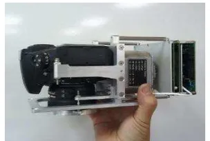
Brican has collaborated with Applanix to integrate and test their new AP20 direct georeferencing system when mated to a Nikon D800 DSLR camera, Figure 16 (Mian 2014). The camera, the IMU and the Applanix AP20 system boards are located on a common mounting frame and calibrated to enable direct georeferenced airborne mapping from a small UAV.
Figure 16: Applanix AP20 DMS and Nikon D800
In the TD100 installation the mounting frame is supported on side rails by antivibration dampers and the combination fits comfortably within the TD100 payload bay, see Figure 17. The International Archives of the Photogrammetry, Remote Sensing and Spatial Information Sciences, Volume XL-1/W4, 2015
International Conference on Unmanned Aerial Vehicles in Geomatics, 30 Aug–02 Sep 2015, Toronto, Canada
This contribution has been peer-reviewed.
Figure 17: AP20 TD100 installation
The unit was initially flown by Applanix in a Cessna 182 using a 50 mm lens on the Nikon and measurements were made of the accuracy for orthographic and stereo imaging (Hutton et al, 2014). The tests were made at altitudes of 1370 m (NS) and 915 m (EW). The resulting accuracy for orthoimage locations was 0.14 m rms and for stereo-imaging 0.6 m rms.
The subsequent tests of the TD100 were made at lower altitudes of 183 m and 221 m as being more representative of its usage. The test had issues with GNSS interference and the accuracies were not resolved. The accuracies are expected to scale from the Cessna tests by the ratios of the test heights. A second flight is planned for later in 2015.
The AP20 platform in the TD100 is very versatile and it can provide a direct georeferencing capability for a variety of sensors that can be fitted within the TD100 main payload bay.
3.4 Beyond Line of Sight Testing and Caribou Tracking
The BLOS testing to be reviewed here was done in coordination with research on endangered woodland caribou by scientists at McGill University at the Goose Bay military PTA (Patterson, 2015). The tests were made in September 2013 and they were permitted under an SFOC issued by Transport Canada because the military controlled the air traffic in the PTA.
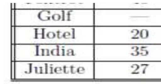
There were eleven BLOS flights in total and five of them explored systematic grid surveys as shown in Figure 18. The aircraft was flown to a maximum distance from the launch point of approximately 35 km. The aircraft carried an ADS-B beacon and the ground station was able to track and display the signal data throughout the flight. During these flights the radio data links were tested and they worked with only a few short dropouts of signal. The Iridium satellite link was also tested it experienced only a few brief dropouts of signal.
The sensors on board the vehicle included the Nikon D3X DSLR camera, the A65 infrared camera and the GoPros for video. All were tested during the BLOS flights and operated without experiencing problems.
The woodland caribou that are of concern can roam sporadically through the PTA site which seriously disrupts the military activities. The herds are in decline (Cosewic,2011) so a census is made each year using manned aircraft and some individuals are tracked year round using satellite equipped collars. The goal of the research was to use the TD100E UAS to take images of the caribou against various types of terrain and ground cover to establish the important parameters for their reliable identification. Since no caribou were within
range of the test area at the time, the research team created surrogate targets suitably sized and shaped to represent caribou for photography.
Figure 18: Grid searches for BLOS tests
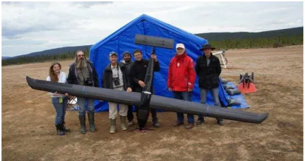
The research team and the Brican operatives are shown at the PTA airfield in figure 19.
Figure 19: Researchers and Brican team for BLOS testing and caribou tracking
The flights were made over six types of ground cover ranging from forests with dense and medium tree coverage, sparse cover with and without lichen, open habitat, and recently burned over areas. The flights were approximately 370 m above ground level using the Nikon D3X DSLR camera and they were conducted during the mid morning and mid afternoon. The images were georeferenced and photo analysts identified and counted the caribou targets that they could detect, enabling the proportion detected relative to the actual number of targets set out in each situation to be derived. A detection rate was found of 75-95% in the more open terrain situations. In the forested situation the percentage fell to 25% for dense coverage and 60% for medium coverage. These rates are similar to those for observers flying in manned aircraft. The analysis enabled many of the critical parameters in caribou detection to be assessed.
The research showed that a quiet, small UAS is a useful means for conducting wild life research when a BLOS capability can be used. A longer range capability is clearly desirable to allow coverage of larger areas in one sortie.
4. Conclusions
manned aircraft and can be used as a platform for evaluating sensors. Its quiet characteristics have proven valuable for wildlife research and its negligible carbon footprint is another consideration when considering survey platforms. The large payload bay of the TD100 can carry larger and bulkier sensors or multiple types of sensors than most other UAS in this size category.
It is clear that agencies will need to permit BLOS operations and longer range capability are needed for future commercial operation of fixed wing small UASs to replace manned aerial operations..
5. References
Bohdanov, D., 2013, Results of flight testing at Burwash Training site, UTIAS Flight Systems and Control, May 2013.
COSEWIC, 2011: Designatable units for caribou (Rangifer tarundus) in Canada, Committee on the Status of Endangered Wildlife in Canada, Ottawa, Canada, pp 1-88
Drela M.,1987, XFOIL: An analysis and design system for low Reynolds number airfoils, MIT Dept of Aeronautics and Astronautics, 1987.
Hutton, J. 2014, Lipa, G., Lutes,, J., Mian, O., Chan, W., DMS-UAV accuracy assessment: AP20 with Nikon D800E, Applanix June 2014.
Koski,W.R., 2014a, Gamage G., Davis A.R., Mathews T., Leblanc B., Ferguson, S., Evaluation of UAS for photographic re-identification of bowhead whales, Baleaena Misticetus. Journal of Unmanned Vehicle Systems, March 2014.
Koski,W.R., 2013b, Thomas, T.A., Funk, D., Michael, A., Marine mammal sightings by analysts of digital imagery versus aerial surveys ; a preliminary comparison. Journal of Unmanned Vehicle Systems, October 2013.
Mian, O., 2014, Direct mapping solution for UAVs, Presentation at UVS Canada meeting, Montreal, November 2014.
Miedlar, P.,1997, Users guide for FAR23 loads program, UDR-TR-96-83, March 1997.
Patterson, C.,2015, Evaluation of a UAV System for Detecting Surrogate Caribou Targets in Labrador, Journal of Unmanned Vehicle Systems, to be published 2015.
Sasse, D.B.,2003, Job-Related Mortality of Wildlife-Workers in the United States 1937-2000, Wildlife Society Bulletin 2003.
6. Nomenclature
agl above ground level BLOS beyond line of sight CG centre of gravity COTS commercial-off-the-shelf
DMS direct measuring system (Applanix) DSLR digital single lens reflex (camera) IMU inertial measurment unit IR infrared
OMNR Ontario Ministry of Natural Resources PTA practice target area
RTK real time kinematic
RPAS remotely piloted aerial system SFOC special flight operations certificate UAS unmanned aerial system
UTIAS University of Toronto Institute for Aerospace Studies Vc cruise speed
VLOS visual line of sight Vs stall speed
The International Archives of the Photogrammetry, Remote Sensing and Spatial Information Sciences, Volume XL-1/W4, 2015 International Conference on Unmanned Aerial Vehicles in Geomatics, 30 Aug–02 Sep 2015, Toronto, Canada
This contribution has been peer-reviewed.