VALIDATION OF GEOGRAPHICAL DATASETS
AGAINST SPATIAL CONSTRAINTS AT CONCEPTUAL LEVEL
A. Belussi a, F. Liguori b, J. Marca b, S. Migliorini a, M. Negri b, G. Pelagatti b, P. Visentini b
a
Dipartimento di Informatica, Università di Verona, Verona, Italy - (alberto.belussi, sara.migliorini)@univr.it
bDEI, Politecnico di Milano, Milan, Italy – (giuseppe.pelagatti, mauro.negri)@polimi.it
Commission IV/8
KEY WORDS: Conceptual modelling of spatial databases, Spatial integrity constraints, Spatial data validation, Model-driven architecture, Geographical applications, Spatial data infrastructures.
ABSTRACT:
A huge amount of geographical datasets are becoming available in distributed environments like Spatial Data Infrastructures (SDI). These datasets are very heterogeneous since they come from different independent sources and surveys and are structured in different formats. In the context of a national SDI that needs to assure an adequate quality level of the data it provides, it is necessary to face the problem of data validation in an uniform way independently from the chosen implementation technology.
In this paper we present the tools and methodology for data validation which have been developed to support the construction of the Italian SDI. These tools are conformant to the relevant ISO 19100 and Open Geospatial Consortium (OGC) standards.
1. INTRODUCTION
The GeoUML Methodology (Belussi et al., 2006) and the
GeoUML Tools (Belussi et al., 2009) described in this paper
have been developed in order to support the management of a geographical Conceptual Schema and to perform the automatic validation of the conformance of a Data Product to a given
Conceptual Schema. The fundamental principles of this
development have been:
• to adhere to the ISO 19100 standards whenever they apply • to be implementable on current technology
• to be independent from any specific (commercially or open) GIS product
• to keep a clear separation between the conceptual and the implementation levels.
The development of this approach has been financed by CISIS, the coordinating authority of Italian Regions for spatial data, in order to guarantee that the spatial databases created by the different Regions satisfy common spatial properties. This is considered a fundamental requirement for the national SDI. A particular difficulty which had to be solved is constituted by the different technical solutions adopted by different Regions for physically storing their databases. For this reason the common data content and the spatial constraints must be defined at conceptual level, but they must be checked on databases implemented with different implementation models. The checking of globally defined conceptual constraints on local databases is necessary and cannot be replaced by a global SDI check on a common GML-based format for several reasons: (i) data quality is also a local requirement; (ii) data surveys must be evaluated at the initial stage of the local spatial database creation; (iii) data have to be checked against integrity constraints during the update process that is managed locally. The tool which manages the Conceptual Schema is called
GeoUML Catalogue; the model used for defining the schema is
called GeoUML (model) (Belussi et al., 2006a; Belussi et al. 2006b). GeoUML and GeoUML Catalogue are described in Section 2.
The tool used for checking whether a Data Product is conformant to a given Conceptual Schema is called GeoUML
Validator and is described in Section 3.
The Data Product to be validated must be implemented using one of several predefined Implementation Models (IM), which transform the Conceptual Schema into a physical structure. Implementation Models are described in Section 4.
The implementation of the GeoUML Catalogue and Validator tools is complete and a beta-testing phase is now underway, as described in Section 5.
The Catalogue and Validator Tools are an example of a “Conceptual Model Driven Architecture”, which can be used to develop other tools, as described in Section 6.
2. GEOUML MODEL AND CATALOGUE
The GeoUML model consists of the following elements: a. the UML model for class diagrams (conceptual schema
language) as defined in (ISO/TC 211, 2005) with some restrictions concerning the use of DataTypes and multiple inheritance
b. a profile of the ISO Spatial Schema (ISO/TC 211 2003), called Extended Simple Feature (ESF)
c. a set of predefined OCL (Object Constraint Language, the reference language for constraint specification in UML) templates which allow to define spatial constraints referring to the classes and attributes of (a) and to the spatial types of (b)
d. a set of additional (optional) specialized features (like, predefined UML schemas for the specification of segmented and subregion properties). These features are not further treated here.
The main extensions in ESF are:
• 3D point and curve types, including 3D spatial relationships between geometries of these types (e.g. the intersection of two 3D curves is defined in 3D), and also a “planar” function which allows to refer explicitly to the 2D projections of 3D geometries
• 2D surfaces with a 3D boundary; in this case topological relationships can refer to the 2D surface (like “planar(point3D) IN surface”) or to the 3D boundary (like “point3D IN boundary3D(surface)”) – these kinds of surfaces are a formally correct way to express topological relationships on geometries which are managed by current GIS technology under several names and are essentially representing 3D rings (the so called “polygonZ” of shapefiles).
As a consequence of the 3D extensions introduced in the ESF model, the constraint templates (c) can express 3D properties. The detailed description of the constraint structure is not given here; refer to (Belussi et al., 2006a; Belussi et al. 2006b)for a description of the template structure and of the reasons why the templates are necessary. It is not convenient and to some extent not even possible to use directly OCL constraints + spatial functions in order to express and automatically verify constraints. Other similar approaches in literature are described in (Demuth et al. 1999, 2001; Duboisset, 2005).
A GeoUML Schema can be created using a tool called GeoUML Catalogue; the Catalogue has the following functions: • it checks that the Schema is syntactically correct directly
during the editing
• it allows to add descriptive information to the formal definitions of the Schema
• it produces documentation of the Schema and additional information (this documentation is necessary in order to support for example a legally mandatory specification for data production)
• it produces a standard OGC ISO 19109 compliant Application Schema (AS) in XMI format which can be imported in a CASE tool; the standard AS is obtained by transforming the ESF spatial types into 19107 Spatial schema types and by converting the constraint templates into standard OCL formulas, which are added as comments to the constrained classes
• it exports and imports the specification in a published XML format (called SCS format).
As an example of the application of the Constraint Templates consider the following textual constraints taken from the D2.8.I.7 INSPIRE Data Specification on Transport Networks – Guidelines:
Requirement 10: In a Transport Networks data set which contains nodes, these nodes shall only be present where Transport Links connect or end.
In GeoUML they would be expressed in the following way, which can be interpreted by the GeoUML Validator:
TransportNode.Geometry (TC) exists
(InNetwork = TransportNode.InNetwork) TransportLink.CenterlineGeometry
which is a short form for the OCL constraint:
context TransportNode
• TransportNode is the class representing nodes in the INSPIRE Specification and it has a spatial attribute Geometry representing the node location
• TransportLink is the class representing links in the INSPIRE Specification and it has a spatial attribute CenterlineGeometry representing the center line of the link
• a.check({r1,…,rn}, b) is a short form for
representing the disjunction of a set of relations (a.r1(b)
or … or a.rn(b))
• InNetwork is a role that defines the object of the class Network to which a NetworkElement (node or link) belongs.
• Finally TC is a short form for the Touch topological relation as defined in GeoUML (it coincides with the Touches relation of SF).
3. GEOUML VALIDATOR
The GeoUML Validator is a Tool which is capable to read a Data Product and to check its conformance with a Conceptual Schema previously created with the GeoUML Catalogue. Since reading a Data Product requires to know its physical structure, the mapping between the conceptual schema and the physical structure must be known to the validator. This problem is treated in the next section.
The aspects which the validator checks are the following: • the structure of the input datasets; e.g. existence of classes
and attributes, domain values, referential integrity, etc… • the validity of each geometry with respect to the properties
of the ESF types (notice that this implies checking also 3D properties, e.g. a 3D ring must be closed in 3D)
• the fulfillment of all spatial integrity constraints which are defined in the conceptual schema.
A critical problem in the implementation of the Validator has been regarding metric aspects and resolution; as it is well known, with current technology it is possible that two different systems evaluate the topology of the same data differently, due to rounding, Floating Point approximation and the use of different algorithms (for example, in the computation of unions used in some kinds of constraints). To deal with these aspects, the GeoUML Validator is based on the following principles: • the resolution of the input dataset must be at least 10 times
less than the internal resolution used by the validator to represent coordinates values
• the minimum distance between any point and any segment is required to be 10 times the internal resolution of the validator
• the evaluation of topological properties is exact, i.e. two points are equal if and only if their coordinates are identical at binary level, two segments are equal if they have equal endpoints, and so on.
A complicated aspect of the error diagnosis is that the validator operates at the physical level but it has to trace back the error to the conceptual level in order to allow its interpretation in terms of the Conceptual Schema; just associating the error with the physical object would not be sufficient, since the Validator’s result has to be interpreted in terms of the conceptual properties which have been violated.
In order to minimize the dependency of the Validator from the physical structure of the input, the architecture of the validator is based on a fundamental component, called the Normalized
Database, which is a PostGIS database having an SQL schema
which is derived from the Conceptual Schema following the internally defined Normalized Implementation Model; a Reader loads the input dataset into the Normalized Database and performs also some controls which depend on the particular input structure, but the main part of the topological controls is done on the normalized database and is therefore independent from the physical structure of the input.
4. IMPLEMENTATION MODELS
The concept of Implementation Model (IM) allows to cover the gap between the conceptual level and the physical level. Every Data Product has a physical structure which is described by some kind of Physical Schema. The way in which the physical schema is defined depends on the technology used for implementing the data product, e.g:
• SQL Data Definition Language for Geo-relational databases
• XML Schema language (XSD files) for GML datasets • a set of void Shapefiles for ESRI© shapefile technology. The details which specialize a Data Product with respect to the Conceptual Schema are stored in a Data Product Specification (DPS); for each Conceptual Schema there can be several DPS (they are all stored in the SCS file associated to the Conceptual Schema). The most important component of a DPS is a data structure called CPMapping, which defines the correspondence between the Conceptual and the Physical Schema.
An Implementation Model is a set of rules which allows to produce from a Conceptual Schema a corresponding Physical Schema and CPMapping.
For every Implementation Model which is added to the architecture it is necessary to develop the following two components:
1. the Mapping Generator: this component is added to the GeoUML Catalogue and allows to produce the Physical Schema and CPMapping by applying the rules of the IM to the Conceptual Schema stored in the Catalogue
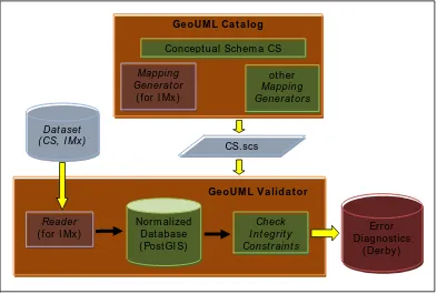
2. the Reader: this component is added to the GeoUML Validator and is capable to read a dataset having a physical schema conforming to the Physical Schema produced by the Catalogue and to load it in the Normalized Database. In Fig. 1 the complete architecture constituted by the Catalogue, Validator, Mapping Generators and Readers is shown.
The Implementation Models can be divided into two categories: Transfer IMs, which should be used for implementing datasets with the aim to transfer information, and Database IMs, which are designed for implementing databases that are conformant to a given conceptual schema. The main difference between these two kinds of IMs is:
• Transfer IMs must be rigidly specified, since the producer and the consumer of the dataset must agree on all details of the physical schema
• Database IMs have more flexibility, so that the database owner can modify some aspects of the physical schema
and CPmapping which is generated (e.g., change the names of tables, attributes, add specific attributes, etc) Currently the IMs which have been implemented in the available tools are the following:
Transfer IMs:
• ESF GML: this IM is based on the standard encoding rules for GML (ISO/TC 211, 2007)
• Shape_Flat: this IM has been defined in order to simplify the aerophotogrammetric data production process and to obtain data which is easily usable with current GIS systems (the technology supporting GML was not considered sufficiently mature)
• Shape_Topo: this IM is similar to Shape_Flat with respect to technology and goals, but it stores the geometries of several classes together in a so called “Topological Layer”, implemented as a shapefile, instead of storing each geometry in the corresponding “Class” shapefile.
Database IMs: there are two general SQL IMs, from which currently the Oracle and PostGIS IMs are derived:
• ESF_SQL_Flat: this IM stores conceptual classes into SQL tables without using nested structures
• ESF_SQL_Monogeometry: this IM is a modification of the previous one, consisting in breaking those SQL tables that contain more than one geometry column – this IM was defined to support the use of some technologies which are not capable of dealing with multiple geometries in a table.
5. CURRENT APPLICATIONS
The Implementation of the Catalogue, Validator and of the Schema Generator and Reader for several Implementation
Models have been completed (available at
www.spatialdbgroup.polimi.it).
The Catalogue has been already extensively used; the most important application has been the definition, in 2009, of the Conceptual Schema of the minimal shared database content of the Italian Regions, called National Core (NC). The NC application has introduced some complications, because the NC has the role of a Meta-specification, i.e. a Reference Specification that all Regional Specifications must include. This has led to the complex problem of compatibility between different specifications, especially since the project aimed to recover also data which has been produced before the definition of the NC, using different schemas. Some features have been introduced in the Catalogue in order to deal with this problem, for example the possibility to compare different schemas, but further study is necessary in order to deal with semantic differences between schemas.
The Beta test of the Validator in Aerophotogrammetric data productions is underway with Veneto Region for the Shape_Flat IM and Region Piemonte for the Shape_Topo IM.
In these productions the validator should be used not only by the tester who has the responsibility to finally accept or reject the data, but also by the data providers.
Figure 1. Validation of a Dataset with Conceptual Schema SC and Implementation Model MIx
During these experiments we hope to better understand how constraints should be written in order to obtain the best possible quality of the provided datasets. An interesting aspect which is emerged already during the Cremona case is that, although the Validator checks only the “intrinsic correctness” of the data, i.e. the consistency of data with itself, since it cannot know anything about the real world, this kind of check allows the tester also to discover many errors with respect to the correspondence between the data and the real world.
6. CONCLUSIONS AND EVOLUTIONS
The GeoUML Validator is a first example of the larger class of GeoUML Tools which could be implemented in this architecture. The main characteristic of these tools is that the work they perform is driven by a Conceptual Schema (SC.scs file). Thus, we can say that each GeoUML tool is based on a
“Conceptual Model Driven” Architecture.
Some tools can be implemented in a very simple way by just substituting in the structure of Fig. 1 the final component, the
Check Integrity Constraints component, with a different
component. For example, possible additional components are: • An Extractor Component, that is able to extract data from
the Normalized database and to represent them in a given Implementation Model. A Converter Tool, that is able of converting data from IMx to IMy can be obtained by just the combination of a Reader for IMx and an Extractor for IMy.
• A Merger Component, that is able to merge two data products that share the same conceptual schema but adopt different IMs. In this case we need two readers, one for IMx and one for IMy, and a Merger that is able to discover common instances and solve attribute conflicts.
These examples show that if the datasets share the same Conceptual Schema, i.e. they share the same content although they are different in physical structure, many useful operations can be performed using an approach based just on Implementation Models. Remark that with most commercially available approaches to data conversion it is difficult to recognize that two datasets with different structures share a common content, because the conceptual and physical levels are not clearly separated.
Real differences of contents (semantic differences) between two datasets must instead be modeled at conceptual level. In order to deal with semantic differences an extension of both the GeoUML Catalogue and of the Merger Component is required. Some experiments have been performed in order to analyze how to extend the GeoUML Tools in order to support elementary semantic differences. The general architecture envisages that the Catalogue must represent the semantic
mapping among elements of the two conceptual schemas, and
the Merger Component has to apply the semantic mapping to the data in the Normalized Database. Although the field of semantic mapping has enormous complexity and only very elementary semantic differences have been experimented, coupling the different IMs with some elementary semantic mappings, like the mapping of domain values, can be extremely valuable in many practical situations.
REFERENCES
Belussi A., Negri M., Pelagatti G., 2006. An ISO TC 211 Conformant Approach to Model Spatial Integrity Constraints in the Conceptual Design of Geographical Databases. In John F. Roddick et al. (ed.) Lecture Notes in Computer Science,
Berlin/Heidelberg, Springer, Proceedings of ER 2006
Mapping Gener at or
( for I Mx )
Concept ual Schem a CS
Check I nt egr it y Const r aint s
ot her Mapping Gener at or s Ge oUM L Ca t a log
Ge oUM L V a lida t or CS.scs
Reader ( for I Mx )
Dat aset ( CS, I Mx )
Nor m alized Dat abase ( Post GI S)
Er r or Diagnost ics
(CoMoGIS workshop), Tucson, AZ, USA, Nov. 6-9 2006, pp.
100-109.
Belussi A., Negri M., Pelagatti G. 2006. Modelling Spatial Whole-Part Relationships using an ISO-TC211 conformant approach. Information and Software Technology (48): 1095-1103.
Belussi A., Migliorini S., Negri N. & Pelagatti G. 2009. From the Conceptual Design of Spatial Constraints to their Implementation in Real Systems. In Proceedings of The 17th
ACM SIGSPATIAL International Conference on Advances in GIS, Seattle, Washington, USA, Nov. 4-6, 2009, pp. 448-451.
Demuth B., Hußmann H. 1999. Using UML/OCL Constraints for Relational Database Design. Proc. of the Conference on the Unified Modeling Language, USA (1999), pp. 598-613
Demuth B., Hußmann H., Loecher S. 2001. OCL as a Specification Language for Business Rules in Database Applications. Proc. of the Conference on the Unified Modeling Language, USA (2001), pp. 104-117.
Duboisset M., Pinet F., Kang M.A., Schneider M. 2005. Precise Modeling and Verification of Topological Integrity Constraints in Spatial Databases: From an Expressive Power Study to Code Generation Principles. 24th International Conference on Conceptual Modeling (ER), Austria (2005), pp. 465-482.
ISO/TC 211, 2003. ISO 19107:2003, Geographic information - Spatial schema, text for FDIS, doc. N 1324, 2002-09-09
ISO/TC 211, 2004. ISO 19125-1:2004 Geographic information - Simple feature access - Part 1: Common architecture, text for IS, doc. N 1563, 2004-01-23
ISO/TC 211, 2005. ISO 19109:2005, Geographic Information - Rules for application schema, text for FDIS, doc. N 1538, 2003-11-26
ISO/TC 211, 2007. ISO 19136:2007 Geographic information – Geography Markup Language (GML), text for ISO, doc. N. 2174, 2007-03-12
OGC, 2010. OCG 06-103r4 OpenGIS Implementation Standard for Geographic information - Simple feature access - Part 1: Common architecture, Version: 1.2.1, 2010-08-04
APPENDIX
Table 1 lists the two most time consuming spatial integrity constraints that have been tested during the application of the Validator on the spatial database of the Municipality of Cremona. The table shows, for each tested constraint: its formal definition (column 1), the constrained class and its cardinality (column 2), the constraining classes and their cardinality (column 3), the number of violations (column 4) and the time required for performing the test (column 5).
The first constraint requires the disjointness or adjacency (DJ or TC) between all elementary volumes (class Volumetric Unit) which are at ground level. The second constraint requires that the 2D projection of the position of all Driveway (which have a 3D point geometry) must be contained inside the surface representing the occupancy of a building at ground level.
The very small amount of violations is due to the fact that the Database was operational and had already been extensively checked and corrected during use and update.
Constraint definition Constrained class (initials) - #obj
Constraining classes (initials) - #obj
Number of violations
Time (in seconds)
(type = "ground")
VOL_UNIT.basic_surface.surface (DJ | TC) forall
(type = "ground")
VOL_UNIT.basic_surface.surface
Volumetric Unit (VOL_UNIT) - 24057
Volumetric Unit (VOL_UNIT) - 24057
2 5160
ACC_PC.Position.PLN (IN) exists
CR_EDF.groundOccupancy.surface
Driveway (ACC_PC) - 23000
Building (CR_EDF) - 21700
12 7320