Manuscript received July 2017, revised September 2017 Copyright © 2017 Universitas Muhammadiyah Yogyakarta - All rights reserved
Customization of 433 MHz Antenna for an ISM Application using
Meanderline Structure
Indar Surahmat
*11Department of Electrical Engineering, Universitas Muhammadiyah Yogyakarta
Kampus Terpadu UMY, Jl Lingkar Selatan Yogyakarta *Corresponding author, e-mail: [email protected]
Abstract – Innovation on ISM devices has been an interensting trend in robotics application. Antenna as a wireless interfacing part in communication between the device and another requires a specific design to fit an available space in the device. This paper explores a customized design of 433MHz antenna for an application of ISM devices. Antenna is designed by using meandeline structure theory. An antenna for the frequency has been simulated and fabricated. The design is implemented in 38mm x 110mm FR-4 PCB with thickness 1.6mm. The antenna has a maximum gain 1.1 dB and SWR 1.83 at the frequency.
Keywords: antenna, ISM, meander line, wireless communication
I.
Introduction
The rapid changing innovation of technology in telecommunication fields, especially the usage of wireless telecommunications in ISM (industrial, scientific and medical) devices has made researchers and scientists giving special attention. The usage of ISM frequency for some purposes is becoming a trend. Some applications has been built to fulfill customer requirements.
In the last two decades, where the development of integrated circuit technology is growing rapidly, some new requirements of devices are appear. The design of devices becomes smaller and customized. Most of the devices provide reduced size and unique design. It consequences that the design of supported parts have to be also customized.
The facts that some designers found difficulties to find available parts in markets which the parts cannot be produced by themselves due to some factors. These facts impacted to the designs where they have to follow the structure of the parts that available in the market.
Antenna is a part of the communication device that located in the outer part. Currently, some antennas is designed to follow the skin shape of the appliance. Some theories are available to support customized design of the antenna. The relevant theories are explored in this paper.
The idea of the research to make a custom shape of antenna came from the same problem. The available antenna is hard to fit space available in the planned device. Then, we made a special antenna for our ISM project. The antenna have to operate at 433MHz in the specific available space. The simulation and measurement are reported in this paper.
The organization of this paper are as the following. Part I is introduction which explains the background of this work. In Part II, we discuss some relevant theories to make the special design and satisfy the requirements. Part III shows the details of our special antenna such as material and dimension. The simulation and measurement result are explored in Part IV. In the Part V, we concluded our work and suggested potential research to be explored in the future related this project.
Copyright © 2017 Universitas Muhammadiyah Yogyakarta - All rights reserved Journal of Electrical Technology UMY, Vol. 1, No. 3
mm, a length of dipole antenna is 346.42mm. Different with dipole, monopole antenna uses a quarter length of lambda which is 173.21mm. Fig. 1 simply pictures dipole and monopole antenna.
2
Fig.1 Simple model of dipole and monopole antenna
II.2. Meanderline Antenna
The another design developed in reduced size and now becoming trend is meanderline antenna. The
Some designs proposed by researchers has fit the requirements in terms of antenna performance. Unfortunately, the antennas do not fit the available space in the unique design of the application. The new model antenna has to be considered.
II.3. Electrically Small Antenna
Meander line antenna is one of forms of Electrically Small Antenna (ESA). Some of studies on ESA investigate the use of meander line antenna for short and very short range application such as ESA antenna. He expresses them into the equations (2), (3) and (4) space in rad/meter, a represents maximum value of enclosing spare radius of the antenna. Then, Q, G and BW is determined using equation (2), (3) and (4) respectively.
Discussing about the value of characteristic impedance, the meander structure is modelled as a CPS (Coplanar Strip) because no groundplane in the other side of PCB. Ghione in [7] describes that the value of characteristic impedance (Z0) can be get by
exploring equation (5). The value of K(k)/K(k’) is antennas is very important factor. An ideal antenna has a value of SWR close to 1. It is common, the acceptable SWR value in real application are between 1 and 2. In other representation, S11 parameter used with value less than -10dB.
The popular relation of SWR to antenna impedance are expressed in equation (7) and (8)
where Γ is reflection coefficient.
(7)
(8)
III.
Proposed Antenna Design and
Research Methodology
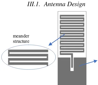
Copyright © 2017 Universitas Muhammadiyah Yogyakarta - All rights reserved Journal of Electrical Technology UMY, Vol. 1, No. 3 III.1. Antenna Design
Fig.2. Proposed full antenna design (copper/front side)
Antenna has 15 turns to form meander line with the details size as the following. The size of l is 34mm, w is 2mm and s is 1.5mm. Fig. 3. represents
l, s and w.
Fig.3. Meander line dimension
For the feeding part, noted as f, the length is 19mm. The design take feeding part in the middle of groundplane as shown in Fig. 4. The space between groundplane and first turn, noted as s1, is
4mm. The length l1 from the center is 17mm. The
space in the groundplane between feeding patch and groundplane itself, noted as s2and s3, are 5mm and
5mm respectively.
Fig.4. Proposed antenna design
Fig. 5. depicts the groundplane area with dimension 40mm x 40mm substracted by feeding part in the middle.
Fig.5. Proposed groundplane design
III.2. Antenna Port Design
The application of this design requires that an antenna port, the design uses RP-SMA port, has to be available in another PCB layer. In here, the design uses a via to feed the antenna. The port is installed in the backside of PCB. Fig. 6 shows a design and dimension of the port.
Fig.6. Port location
III.3. Simulation Setup
This research performs simulation using 3D FEM (Finite Element Methods) frequency domain simulation software to gain a good approach in designing required antenna specification. The simulation is done in some steps as follows :
1.Designing 3D model of the antenna in the software.
2.Setting Parameter of Antenna. 3.Validating the Design
groundplane meander
Copyright © 2017 Universitas Muhammadiyah Yogyakarta - All rights reserved Journal of Electrical Technology UMY, Vol. 1, No. 3
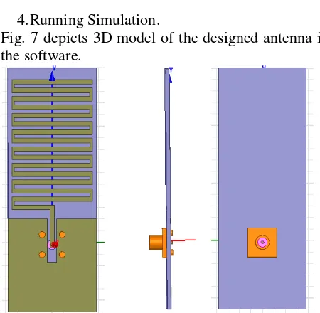
4.Running Simulation.
Fig. 7 depicts 3D model of the designed antenna in the software.
Fig.7 3D model of the antenna in the FEM simulator.
III.4. Hardware Implementation and Measurement
Fig.8 shows the implementation of meander line antenna designed for 433MHz application. The antenna is implemented in the dimension specified. We use etching technic to form meander line in the FR-4 PCB. This technic is still an acceptable way and results a good precision in dimension of the implemented hardware.
Fig.8. Physical Antenna Implementation
The research uses RigExpert AA1400 Antenna Analyzer to perform physical antenna parameter measurement. This tool has feature to measure VSWR and antenna impedance (ZL).
IV.
Result and Discussion
We only discusses some important parameters in this paper. They are antenna gain and radiation pattern and reflected power (VSWR).
IV.1. Antenna Gain and Radiation Pattern
Our proposed antenna has a good omni-directional radiation pattern. It has maximum performance at theta 0deg in all phi. Moreover, the antenna has minimum performance at theta 90deg with phi equal to 90deg and -90deg. It can reach maximum gain about 1.1 dBi at the theta 0deg. Since this antenna will be located in the front face of the device, it radiation pattern will fit the requirement. The beam of the antenna can reach maximum performance to the front side of the device. Our scenario in this design, we put the feeding port through via hole in order to ensure radiation pattern of the antenna achieve maximum at the front side. Fig. 9 exhibits radiation pattern of the proposed antenna in H and E plane.
.
Copyright © 2017 Universitas Muhammadiyah Yogyakarta - All rights reserved Journal of Electrical Technology UMY, Vol. 1, No. 3 IV.2. Standing Wave Ratio
From the measurement result, we obtain SWR data as shown in Fig.10. The data is represented in S11 parameter. It can be seen that working bandwidth (usually -10 dB ) for the antenna is from 430MHz to 440MHz. In here, we have 10 MHz
420.5 424.25 428 431.75 435.5 439.25 443 446.75
S value complies the requirement of the application. The value of load impedance (ZL) can be calculated
and the result is 27.3 Ω.
Furthermore, there is a potential research can be extended. Adding impedance matching network can increase performance of the antenna.
V.
Conclusions and Future Works
Regarding the analysis, we conclude some points as the followings.
a.A meander line antenna can be used as alternative to fulfill available space requirement since the form of the antenna can be adjust to some dimension as long as it still follows the rule. b.The investigation on radiation pattern shows the
meander line antenna has omni-directional pattern. There is a challenge to make a directional pattern antenna.
c.The maximum gain of the antenna can be achieved for this design is 1.1 dBi. It will enable for this antenna to be used in some short range ISM application. Although we have optimized the design, to increase the gain, there are some other concepts can be explored deeper for the future works.
d.The SWR at the frequency exhibits that this antenna has fulfilled the requirement. However, we are still work on implementing lumped elements to make a better impedance matching. .
Acknowledgements
This work is a part of Designing Antenna for ISM Application Project funded by Universitas Muhammadiyah Yogyakarta through University Research Grants year 2017. The simulation and measurement are done at Telecommunication Laboratory, Department of Electrical Engineering Universitas Muhammadiyah Yogyakarta.
References
[1] Ryu, H. K., Lim, S. , Woo, J. M., 2008. Design of electrically small, folded monopole antenna using C-shaped meander for active 433.92 MHz RFID tag in metallic container application, Electronics Letters, Volume: 44, Issue: 25 Pages: 1445 - 1447, DOI: 10.1049/el:20082848
[2] Wang, X.Y., et.al, 2015. “A Compact 433MHz
Antenna with Enhanced Performance by Using Multi-Resonant Meander Line Structure”, Asia -Pasific Microwave Conference (APMC), Year: 2015 Volume: 2 Pages: 1 – 3, DOI: 10.1109/APMC.2015.7413052
[3] Loutridis, A., John, M., and Amman, M.J., “Folded
Meander Line Antenna for Wireless M-Bus in the VHF and UHF bands” , Electronic Letters , 23rd July 2015 Vol. 51 No. 15 pp. 1138 - 1140
[4] Hsu, C.C, Song, H.H, 2013. “Design, Fabrication, and Characterization of a Dual-B and Electrically Small Meander-line Monopole Antenna for Wireless Communications” International Journal of Electromagnetics and Applications, DOI : 10.5923/j.ijea.20130302.04
[5] Wheeler, H.A, 1947. “Fundamental Limitation of
Small Antennas”, Proceeding of the IRE, vol. 35, no. 12, pages : 1479 – 1484, 1947
[6] McLean, J.S., 1996. “A Re-examination of
Fundamental Limits on the Radiation Q of Electrically Small Antennas”, IEEE Transactions on Antennas and Propagation, volume 44, no. 5, pages : 672 – 676.
[7] Gionne, G., 1984. “Analytical Formulas for
Coplanar Lines in Hybrid and Monolithic MICs”, IEEE Electronics Letters, vol.20, no. 4, pages : 179 – 181.
[8] Hilberg, W., 1969. “From Approximations to Exact
Relations for Characteristic Impedances”, IEEE Transactions on Microwave Theory and Techniques, volume 17, no. 5, pages : 259 – 265.
Copyright © 2017 Universitas Muhammadiyah Yogyakarta - All rights reserved Journal of Electrical Technology UMY, Vol. 1, No. 3
Authors’
information
Indar Surahmat is currently a researcher in the Department of Electrical Engineering, UMY. He got bachelor degree in electrical engineering at UGM, Indonesia (2005) and master degree in telecommunication engineering at ITB, Indonesia (2011). Previously, he had worked at some multinational companies which provide services in telecommunication sector.
He is interested in two streams of telecommunication. Those are antenna and wave propagation, and teletraffic engineering. He is also a supervisor of some students in the same department majoring in telecommunication.
Mr Surahmat is also the member of the Institution of Engineers Indonesia and APTI, the association of engineering professional Indonesia.