MODUL PERKULIAHAN
Perencanaa
n Produk
Kajian Paten
Fakultas Program Studi Tatap Muka Kode MK Disusun Oleh
Teknik Teknik Mesin
04
13039 Darwin Sebayang Mohd. Fahrul bin HasanAbstract
Kompetensi
Modul ini berisi contah kajian paten
Kajian Paten
1. Pendahuluan
2. Review of Available Patented Apparatus in the Market
The several of manufacturing methods and apparatus on the previous patents are reviewed and summarized in the following section. The revision are consists of method used, background of the invention and manufacturing processes.
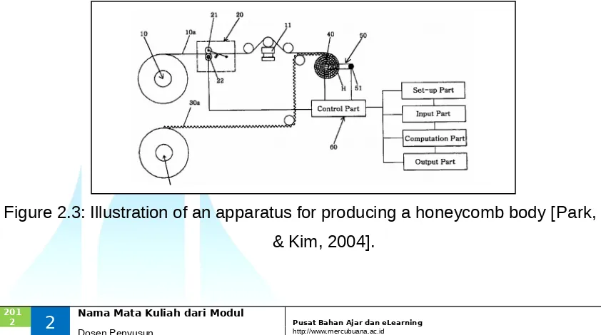
2.1 Apparatus for Producing a Honeycomb Body (Park, Moon & Kim, 2004)
The apparatus of this invention is producing a honeycomb body, which can produce precise dimensions to insert into a metal outer shell accurately. The spiral shaped honeycomb body is made by folding a flat and corrugated sheet metal into a roll. The invention is to prevent a separating between the honeycomb body and the metal outer shell if the outer diameter of the honeycomb body is less than the inner diameter of the metal outer shell. On the other hand, if the outer diameter of the honeycomb body is larger than the inner diameter of the metal outer shell, it is impossible to insert without damaging the shape of honeycomb body. The apparatus includes a roll part for supplying a thin metal flat sheet via several rolls, a part for measuring the length of the flat sheet metal, a part for supplying a corrugated sheet metal via several rolls, a winding roll of a honeycomb body which is made by folding the overlapping flat and corrugated sheet metal into a roll, a part for measuring the rotation angle of winding roll and a control part which controls the amount of winding in a roll of a honeycomb body. Figure 2.3 illustrates an apparatus for producing a honeycomb body.
2.2 Methods for Manufacturing by Heat Treatment of Metals (Solntsev
et al.,
2000)
The invention relates to monolithic metal oxide structures made from metals and
methods for manufacturing the spiral catalyst substrate by heat treatment of metals.
This method was attempt to manufacture because of there is a need for metal oxide
structures which are of high strength, efficiently and inexpensively manufactured in
environment benign processes. There also is a need for metal oxide structures which
are capable of providing refractory characteristics such as are required in demanding
temperature and chemical environment and having a variety of shapes and wall
thicknesses.
The manufacturing process of this method is starting with the disk comprises
a first flat sheet of steel adjacent a second corrugated sheet of steel, forming a
triangular cell (mesh), which are rolled together to form a disk of suitable diameter.
Then, the metal containing spiral structures were heated to a temperature below the
melting point of metal to form a monolithic metal oxide structure having substantially
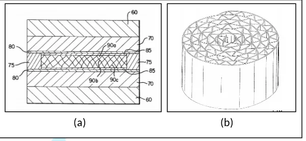
the same shape. Figure 2.4 shows the drawings of the invention.
Figure 2.4: (a) is a side view of an assembly suitable for processing metal structures
according to process of the invention; (b) is a plan view of an exemplary metal
structure shaped [Solntsev
et al.,
2000].
2.3 Multi-point Welding Method (Matsuo
et al.
,1995)
The invention relates to a method of welding multi-points to be welded for a short
time for producing a spiral catalyst substrate. In the catalyst structure, the flat sheet
metal needs to be welded to the corrugated sheet metal for preventing separation of
layers. This method also provide a multi-point welding method wherein multi-points
to be welded are certainly welded for a short time.
An alternately laminating a flat and corrugated sheet metal were formed into
approximately cylindrical base body as a beginning of manufacturing process of this
method. Then, the laminating of a sheet metal is wound in a spiral shape. An
electrode apart is mounted from one end surface of the base body. Finally, the
electric discharges are generated to fuse and join the contact points of the flat sheet
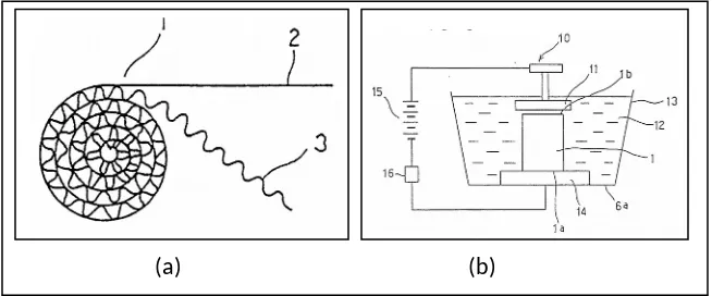
to the corrugated sheet. Figure 2.5 shows the drawings of multi-point welding
method.
Figure 2.5: (a) is an explanatory view showing a forming process of flat and
corrugated sheet metal; (b) is an explanatory view showing a welding process by
electric discharges [Matsuo
et al.
,1995].
2.4 Apparatus for Shaping a Spiral Catalyst Support (Retallick, 1987)
The spiral structure is simple to build, but it has suffered from a major disadvantage
the spiral structure telescope outwardly, due to the pulsating exhaust of the
automobile. Therefore, the apparatus for shaping a spiral catalyst support was
invented to solve this problem, which the invention able to prevents telescoping of
the layers of the spiral catalyst support so that the invention does not require brazing
of the sheet metal.
The catalyst support is made by first winding a flat and corrugated metal strips
to form a spiral shaped structure. Then, the strips are wound together on a mandrel,
which is removed after the winding to leave an axial hole. The structure after being
inserted into a cylindrical tube is flattened at each end and to provide a continuously
tapered catalyst support. Finally, the tapers in the support insure that the layers of
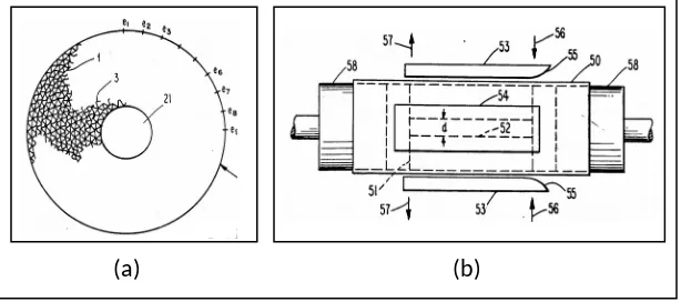
the spiral cannot telescope outwardly in either direction. Figure 2.6 shows the
drawings of the invention.
Figure 2.6: (a) is an end view of a metal catalyst support before it has been flattened,
also showing the layers in fragmentary form; (b) is a side view of the apparatus used
in the method of making the catalyst support of the invention [Retallick, 1987].
2.5 Spiral Catalyst Substrate Produced by the Previous Inventions
The manufacturing processes of spiral catalyst substrate on the previous inventions
which had discussed above are compared according to the material and geometries
of the spiral catalyst substrate and are summarized as in Table 2.1.
Table 2.1: Review of catalyst substrate produced by the previous patented
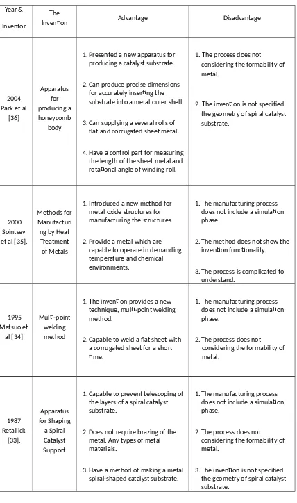
2.6 The Advantages and Disadvantages of the Previous Inventions
The patents have advantages and disadvantages of their invention which can be
seen the summarization in Table 2.2. From these summaries, the process can be
easily understood in order to recognize the gap in the literature.
Table 2.2: Review of patented apparatus and methods of manufacturing a spiral catalyst substrate
1. Presented a new apparatus for producing a catalyst substrate.
2. Can produce precise dimensions for accurately inserting the substrate into a metal outer shell.
3. Can supplying a several rolls of flat and corrugated sheet metal.
4.Have a control part for measuring the length of the sheet metal and rotational angle of winding roll.
1. The process does not considering the formability of metal.
2. The invention is not specified the geometry of spiral catalyst substrate.
1. Introduced a new method for metal oxide structures for manufacturing the structures.
2. Provide a metal which are capable to operate in demanding temperature and chemical environments.
1. The manufacturing process does not include a simulation phase.
2. The method does not show the invention functionality.
3. The process is complicated to understand.
1. The invention provides a new technique, multi-point welding method.
2. Capable to weld a flat sheet with a corrugated sheet for a short time.
1. The manufacturing process does not include a simulation phase.
2. The process does not
considering the formability of
1. Capable to prevent telescoping of the layers of a spiral catalyst substrate.
2. Does not require brazing of the metal. Any types of metal materials.
1. The manufacturing process does not include a simulation phase.
Daftar Pustaka
[1] B.L. Lester, "Implementing technology-forcing policies: "The 1970 clean air act
amendments and the introduction of advanced automotive emissions control in the
United States,"
Technological Forecasting and Social Change,
vol.
72, 2005, pp.
761-778.
[2] V.T. Martyn, "Roles of catalytic oxidation in control of vehicle exhaust emissions,"
Catalysis Today,
vol. 117, 2006, pp. 407-418.
[3] T. Shamim, and H. Shen, "Effect of geometric parameters on the performance of
automotive catalytic converters,"
International Journal of Science and Technology,
vol.
14, 2003, pp. 15-22.
[4]
R.M. Heck, and R.J. Farrauto, "Environmental catalysis into the 21st century," Catalysis Today, vol. 55, 2000, pp. 179-187.[5] M. Valentini, G. Groppi, C. Cristiani, M. Levi, E. Tronconi, and P. Forzatti. "The deposition of γ-Al2O3 layers on ceramic and metallic supports for the preparation of structured catalysts,"
Catalysis Today, vol. 69, 2001, pp. 307-314.
[6] D. Betta et al. at R.E.Hayes and S.T. Kolaczkowski. Introduction to Catalytic Combustion.
Amsterdam: Gordon and Breach Science Publishers, 1997.
[7] X. Wu, D. Weng, S. Zhao, and W. Chen. "Influence of an aluminized intermediate layer on the adhesion of a γ-Al2O3 washcoat on FeCrAl," Surface & Coating Technology, vol.190, 2005, pp. 434-439.
[8] R.M. Heck and R.J. Farrauto, "Automobile Exhaust Catalyst Applied Catalysis," A General vol.221, 2001, pp. 443-457.
[9] B.B.Gosh, P.C. Roy, P.P.Gosh, M.N. Gupta, and P.K.Santra, "Control of SI engine exhaust emission using ZSM-5 supported Cu-Pt bimetals as a Catalyst," SAE International, 2002-01-2147, 2002 [10] Higashiyama,K., Nagayama,T., Nagano,M., Nakagawa,S., Tominaga,S., Murakami,K. and
Hamada,I, "A catalyzed hydrocarbon trap using metal-impregnated zeolite for SULEV systems,"
SAE International, 2003-01-0815, 2003.
[11] D. Sebayang, P. Untoro, Y. Putrasari, Y.H. Soon, M.Hashim, and M. Ghomma, “Influence of difference deposition technique of nickel on FeCrAl metallic monolith," Malaysian Metallurgical Conference, 2009.
[12] R.A. Searles, "Contribution of automotive catalytic converters," in Material Aspects in Automotive Catalytic Converters, H. Bode, Ed. Germany: Wiley-VCH, 2002, pp. 3-16.
[13] R. Bruck, "Development status of metal substrate catalyst," in Material Aspects in Automotive Catalytic Converters, H. Bode, Ed. Germany: Wiley-VCH, 2002, pp. 19-30.
[14] Quadakkers, W.J., and Bennet, M.J. (1994). Materials Science and Technology, 10, pp.126-132. [15] Amano, T., Watanabe T., and Michiyama, K., (2000). Oxidation of Metals, 53, Nos. 5/6, pp.
30-35.
[16] S. Rajadurai, S. Jacob, C. Serrel, R. Morin, and Z. Kircanski, "Wiremesh substrate for oxidation, TWC and SCR converters," Advanced Propulsion & Emissionet, 2006, pp.97-105.
[17] K. Oouchi, K. Shibata and K. Nishizawa, "Development of thinnest wall catalyst substrate," SAE Paper, 2002-01-0358, 2002.
[18] Kolb-Telieps, J. Klower, R. Hojda, and U. Heubner, "A new production technique for FeCrAl," in
Material Aspect in Automotive Catalytic Converters, H. Bode, Ed, Werkstoff-Informationsgesselschaft, 1997, pp.99-104.
[20] H. Bode, "Lifetime predictions of uncoated metal-supported catalysts via Modelling and simulation, based on reliable material data," in Material Aspects in Automotive Catalytic Converters, H. Bode, Ed. Germany: Wiley-VCH, 2002, pp. 134-143.
[21] Y. Miyairi, T.Aoki, S. Hirose, Y. Yamamoto, M. Makino, S. Miwa, and F. Abe, "Effect of cell shape on mass transfer and pressure loss," SAE Internationals, 2003-01-0815, 2003.
[22] M. Chen, J. Aleixo, S. Williams, and T. Leprince, "CFD modelling of 3-way catalytic converter with detailed catalytic surface reaction mechanism," SAE Internationals, 2004.
[23] S.H. Aminordin, "Computational fluid dynamics (CFD) analysis for a catalytic converter design," Thesis (M. Eng), Fakulti Kejuruteraan Mekanikal dan Pembuatan, Universiti Tun Hussein Onn Malaysia, 2008.
[24] D. Sebayang, P. Untoro, A.R. Hamimah, C.T. Lim, and M.I.S. Azizan, "The application of natural zeolite to reduce harmful gases from exhaust system," 5th International Materials Technology Conference and Exhibition, 2006, Malaysia: Institute of Materials Malaysia (IMM).
[25] D. Sebayang, S.H Amirnordin, P. Untoro, and A.R. Hamimah, "Current status on the
development of catalytic converter project. 1st," Malaysian Technical University Colleges Annual
Conference on Engineering and Technology (MUCET), 2006.
[26] A.R. Hamimah, K.F. Shahrudin, R.A. Ainun, and B. Hatijah, "Development of SiC-zeolite Porous ceramic. Conference on applied sciences, 2006, Malaysia: UiTM.
[27] A.R. Hamimah, R.A. Ainun, B. Hatijah, and F.S. Khairul, "Influence of additive and sintering temperature on porous ceramic properties," International Conference on Solid State Science and Technology, 2006, Malaysia: KUSTEM.
[28] I. Garrn, C. Reetz, N. Brandes, L.W. Kroh and H. Schubert, "Journal of the European Ceramic Society," vol. 24, 2004, pp. 579-587.
[29] A.R. Hamimah, and C.G. Yap, "Preparation of ceramic foam by simple casting process," PSU-UNS International Conference on Engineering and Environment(ICEE-2007), 2007.
[30] R. M. Heck, R.J. Farrauto, and S.T. Gulati, Catalytic Air Pollution Control Comercial Technology 2nd
ed, New York: John Wiley & Sons, Inc, 2002, pp. 79-80.
[31] US Patent, "NiO Catalyst Configuration, Methods for Making NOx Adsorbers, and Methods for Reducing Emissions," No. US6,930,073B2., Aug. 16, 2005.
[32] ThyssenKrupp VDM, Aluchrom Yhf, Material Data Sheet No. 4049, March 2008 Edition, Germany.
[33] W.J. Quadakkers, and L. Singheiser, Materials Science Forum, vol. 77, 2001, pp. 369-372. [34] D. Naumenko, Effect of Metallurgical Chemistry and Service Condition on the Oxidation Limited
Life Time of FeCrAl-based Components, PhD Thesis, RWTH Aachen, 2001.
[35] P. Untoro, M. Dani, H.-J. Klaar, J. Mayer, D. Naumenko, J.C. Kuo, and W.J. Quadakkers, "The effect of trace amounts of Mg in fecral alloys on the microstructure of the protective alumina surface scales", Proceeding of MACC, 2001,pp. 271-277.
[36] M. F. Hassan, D. Sebayang P. Untoro, "Conceptual design of a spiral catalytic support",
International Conference on Mechanical & Manufacturing Engineering (ICME 2008), 2008. [37] M. F. Hasssan, D. Sebayang , P. Untoro, "Apparatus for producing a spiral shape of corrugated
sheet metal for substrate of catalytic converter", ICAME 09, Malaysia, 2009.
NOMENCLATURE
CFD Computational Fluid Dynamics
CO carbon monoxide
CO2 carbon dioxide
FeCrAl ferum chromium aluminium
HC hydrocarbon
NOx nitrogen oxide
O2 oxygen
OSC oxygen storage capacity
Pd paladium
Pt platinum
Rh rhodium
rpm revolution per minute
SiC silicon carbide
TWC 3-way catalyst