TORSION STRENGTH OF ROUND BAR A6061 FRICTION WELD JOINT
INFLUENCED BY FRICTION TIME, UPSET FORCE AND ONE-SIDE CONE
GEOMETRY
Yudy Surya Irawan1, Wahyono Suprapto, Tjuk Oerbandono, Aulia Rizeky January, Arifin Kekar
Maheru Wijaksono,Rifyal Fauzan
Mechanical Engineering Department, Faculty of Engineering, Brawijaya University Corresponce author : 1 [email protected]
ABSTRACT
Effect of friction time, upset force and one-side cone geometry on torsion strength of A6061 round bar friction weld joint was studied. Round bar commercial A6061 was friction welded with initial compression force of 2.5 kN on stationary part and the rotated part had revolution speed of 1600 rpm with variation of friction time of 45, 50 and 55 minutes. In the upset stage, the variation of upset force of 5 kN, 7.5 kN and 10 kN with the same upset holding time of 110 seconds. The stationary part of the specimen had friction area with variation of cone geometry that represented with ratio of upper diameter, D1 and lower diameter, D2,
D1/D2. It was found friction time and the ratio
of D1/D2 affected torsion strength in the upset
force below 10 kN. In case of the higher upset force of 10 kN, the upset force more dominant to affect torsion strength of the continuous drive friction weld (CDFW) joint. The specimen with maximum torsion strength has more precipitates in grains of microstructures compared to that of specimen with lower torsion strength.
Keywords: Continuous drive friction welding, aluminum, friction time, upset force, one-sdie cone geometry, torsion strength.
1. INTRODUCTION
Aluminum alloys A6061 is aluminum alloy that contains alloys of magnesium (Mg) and silicon (Si). This kind of aluminum alloy is found in wide applications such us machine components, ships, aircraft structures, heavy vehicles and rail transportaions (Bauccio, 2001). It is due to its properties that it has moderate tensile strength, good formability, good weldability and good corrosion resistance which is better than A2024 alloys (Budinski, 1996). However, there is difficulty in joining
this alloys and other aluminum alloys using conventional welding technique. It occurs due to the existance of aluminum oxide that exist during melting in welding and the high thermal conductivity that makes heat difficult to be concentrated in the joint region to yield good weld joint (Charit et.al., 2002).
The difficulty to join Aluminum can be solved using solid state welding process such us friction welding. Friction welding is one of manufaturing method to join metal or non metal by using heat generated from friction on part that to be joined. The weld joint is the result of coalescence of materials under compression state when the specimens rotate or relatively move each other (Zhang, et.al, 2006). Friction welding method that appropriate to join round bar of pipe metal is continuous drive friction welding (CDFW) which also known as rotary friction welding or spinning friction welding. This method can generate heat from friction between the rotated and stationary contact surface under compressive force.
chamfer angle become another parameters that can influnce the strength of the CDFW joint Mohandas (2007) and Irawan et.al.(2016a) also confirm that surface roughness of the friction area can also affect the tensile strength of CDFW joint. Mohandas (2007) found that the increasing roughness Ra up to 5 µm can increase the notch tensile strength, but the strength become lower for surface roughness over 5 µm due to the banded microstructures. properties that is important for component that endures torsion load such us shaft in engine or generator. It is static mechanical properties but it can be used to ensure the strength and the safety of the shaft. Irawan et.al (2016b) studied about torsion strength of CDFW joint. They used one side cone geometry at the stationary friction area to increase torsion strength of CDFW joint. They found that cone geometry with smaller ratio of higher diameter and lower diameter which formed almost complete cone geometry in the stationary part of specimen can produce higher torsion strength of CDFW joint. However, the effect of friction time, upset force and one-side cone geometry on strength of CDFW joint especially torsion strength is not uncovered yet in order to improve torsion strength of A6061. This paper reveals the effect of friction time, upset force and one-side cone geometry on torsion strength of A6061 CDFW joint based on torsion strength test, macro and microstructure analysis, micro-hardness test and temperature measurement on formed flash.
2. MATERIALS AND METHODS
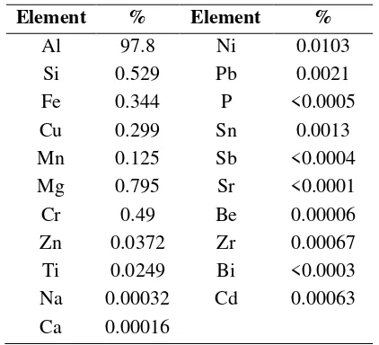
Material used in this study was commercial round aluminum alloy A6061. This alloy has main alloys of Magnesium and silicon. Table 1 shows chemical composition of A6061 used in this study. Round bar A6061 with diameter of 22.5 mm was cut using a saw
Table 1. Chemical Composition of A6061 (% of weight) coolant to prepare CDFW specimen. Geometry of CDFW specimen that machined by turning process can be seen in Figure 1. CDFW specimen has two parts which are rotated part and stationary part. In this case, rotated part is the left side which has flat friction and statinonary part is the right part that has one side cone geometry that represented as ratio of D1/D2=0; 0,25; 0,65; 0,8; 1.
Figure 1. Shape and dimension of CDFW specimen with ratio of cone geometry
down and the CDFW specimen that yields flash dut to friction welding process was continued to endure upset force of 5, 7.5 and 10 kN for 110 seconds and then cooled in the air. In the range of this study, the selection of maximum upset force of 10 kN was done to ensure the safety of the machine structure and the CDFW process.
Friction weld specimen was machined to produce torsion strength testing specimen according to Figure 2. Location of CDFW joint was in the center of the specimen. Torsion strength test was conducted using the torsion strength testing machine. Torsion loading during the test was controlled by giving angle of twist to the specimen with speed of 1 degree/second until the specimen fractured. There were three replications of CDFW specimens for each variation of friction time, up set force and one side-cone geometry.
Figure 2. Geometry of torsion strength test (ASTM, 2004).
Observation was also performed on macro and microstructures of CDFW joint. Weld joint contains three zones of fully plasticized zone (Zpl) in the center and partly deformed zone (Zpd)(Ozdemir, 2005). In the Zpl zone, there are Zpl1 in the center and Zpl2 which is beside of Zpl1 (Irawan et.al., 2016). Area of Zpl1, Zpl2 zones and porosity zone were measured using ImageJ software. The hardness of Zpl1, Zpl2 and Zud were also measured using micro-Vickers hardness method with 50gf force indentation load for 6 seconds.
3. RESULT AND DISCUSSION
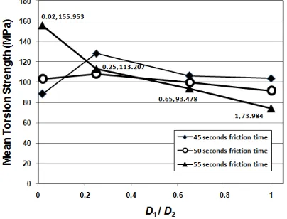
Figure 3 illustrates relationship of D1/D2
ratio and torsion strength of CDFW joint with initial compression force of 2.5 kN and upset force of 5 kN. It shows that D1/D2 ratio
influenced torsion strength of A6061 CDFW joint, in which the lowest D1/D2 ratio of 0.02
with friction time of 50 seconds gave maximum torsion strength of 120.63 MPa.
Friction time at each D1/D2 ratio has different
effect on torsion strength of CDFW joint. It shows that D1/D2 ratio has more significant
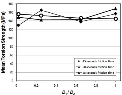
effect on torsion strength of CDFW joint than friction time. In addition, friction weld joint has different properties to withstand torsion load compared to tensile load that perpendicular to CDFW joint. The same results are showed in Figure 4 and 5 that in friction time of 55 seconds with D1/D2 ratio of 0.02 and
upset force of 7.5 kN give maximum torsion strength of 155.95 MPa. Meanwhile, for the specimen with friction time of 55 seconds with upset force of 10 kN and D1/D2 ratio of 1 or
without cone geometry give maximum torsion strength of 168.63 MPa which is 20.7% higher than torsion strength (139.71 MPa) that reported by Irawan et.al. (2016b). In case of
Figure 3. Mean torsion strength of A6061 CDFW joint with 5 kN upset force versus friction time, and cone geometry ratio D1/D2.
Figure 5. Mean torsion strength of A6061 CDFW joint with 10 kN upset force versus friction time, and cone geometry ratio D1/D2.
Figure 6. Mean torsion strength of A6061 CDFW joint with various upset force an10 kN
upset force versus friction time, and cone geometry ratio D1/D2.
specimen with upset force of 10 kN, the effect of upset force is more dominant to give effect on torsion strength of CDFW joint that one side cone geometry, so that specimen with D1/D2 ratio of 1 yields maximum torsion
strength of CDFW joint followed by specimen with D1/D2 ratio of 0.25 and friction time of 45
seconds that has torsion strength of 165.11 MPa.
Figure 6 shows selected data for torsion strength of CDFW joint that has maximum torsion strength for each upset force. It is found that maximum torsion strength occurred in the specimen with upset force of 10 kN and friction time of 55 seconds and ratio D1/D2
ratio =1. It is thought that in higher upset force, the effect of upset force is more dominant than friction time and one-sied cone geometry (D1/D2). It is supposed that with longer friction
time and higher D1/D2 makes higher heat input
to soften the weldment and more easily to more plastically deformed by high upset force (10kN). As the result of higher portion of plastic deformation during upset stage, the weldment has more slips and dislocations that supposed to have higher hardness to yield higher torsion strength. It is tought that the effect of one-side cone geometry will be take more effect in lower friction time compared to the range in this study due to its lower heat input during CDFW process.
Figure 7 shows macrostructure in longitudinal section of 13 mm diameter torsion specimen tof CDFW joints for specimen with D1/D2 = 1, friction time of 55 seconds, 10 kN
upset force that has maximum torsion strength. It has three zones of Zpl1, Zpl2 and Zpr (porosity zone). Figure 8 shows of that for CDFW specimen with D1/D2 = 0.02, friction
time of 45 seconds that has low torsion strength. The area for each (Zpl1, Zpl2, Zpr) was measured by ImageJ software and the strength
Figure 7. Longitudinal section macrostructure of CDFW specimen with D1/D2 = 1, friction
time of 55 seconds and upset force of 10 kN with maximum torsion strength.
Gambar 8. Longitudinal cross section of CDFW specimen with D1/D2 = 0.02, friction
Table 2. Area of each zone in CDFW joints that have maximum torsion strength for specimen with D1/D2 = 1, and minimum torsion
strength for specimen with D1/D2 = 0.02.
Friction time (s)
D1/D2
Area of (mm2)
Zpl1 Zpl2 Zpr
55 1 17.696 18.435 0.279
45 0.02 34.388 15.084 0
Table 3. Micro-hardness of CDFW joint that have maximum torsion strength for specimen with D1/D2 = 1, and minimum torsion strength
for specimen with D1/D2 = 0.02.
Friction time (s)
D1/D2
Region of mean hardness (VHN)
Zpl1 Zpl2 Zud
55 1 157.63 142.43 151.06
45 0.02 135.9 156.43 177.3
results were shown in Table 2. It can be seen that specimen with higher torsion strength D1/D2 = 1 has smaller area of Zpl1 and Zpl2
that has porosity, Zpr of 0.279 mm2, compared
to area of Zpl1 and Zpl2 for specimen with lower torsion strength which has D1/D2 = 0.02
and friction time of 45 seconds. It has correlation with the mean hardness at those zones as shown in Table 2. It is found that mean hardness in Zpl1 for specimen with maximum torsion strength is higher than that of specimen with minimum torsion strength and D1/D2 = 0.02. Higher hardness in ZPl1
zone contributes to higher torsion strength of CDFW joint, even there is small portion of porosity in the weldment.
Figure 9 is thermal cycles for two specimens with maximum and minimum torsion strength. Temperature was measured on the formed flash of CDFW from beginning to the end of CDFW process using Infra-Red Thermogun. It can be seen that thermal cycle for specimen with D1/D2 = 1 is higher with
maximum temperature of 201.6oC. Meanwhile,
maximum temperature for specimen with D1/D2 = 0.02 is 184.4oC with different value of
16 oC. In this state, it is thought that heat input
for specimen with D1/D2 = 1 is little higher
than specimen with D1/D2 = 0.02. The higher
Figure 9. Thermal cycle during friction welding for specimen with maximum torsion strength D1/D2 = 1, friction time of 55 seconds
and the minimum torsion strength with D1/D2 =
0.02 , friction time of 45 seconds with upset force of 10 kN.
(a)
(b)
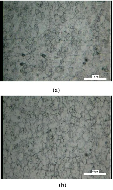
Figure 10. Microstructures for Zpl1 zone in CDFW joint for specimen with (a) maximum
torsion strength, D1/D2 = 1dan (b) minimum
(a)
(b)
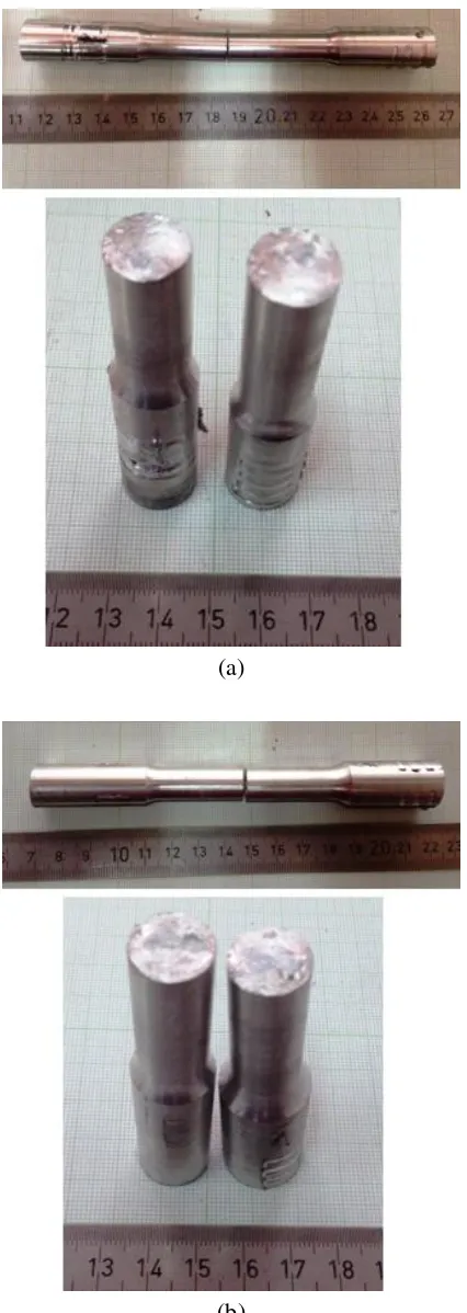
Figure 11 Fracture surface of torsion strength CDFW specimen for (a) D1/D2 = 1, friction
time of 55 seconds with maximum torsion strength, (b) D1/D2 = 0.02 with frition time of
45 seconds and upset force of 10 kN.
heat input and the effect of higher upset force of 10 kN makes precipitates more dispersed in to the aluminium matrix grains as shown in Figure 10. More gray color in the aluminum grains contains more precipitates of Mg2Si
contributes to yield higher hardness in grains (Irawan et.al.,2016b). According to Figure 10, even there is no significant difference of grain size in two specimen microstructures. However due to more precipitates exist in the grains of specimen with D1/D2 =1, the higher hardness
occurred in Zpl1 zone as shown in Table 3. Therefore, specimen with D1/D2=1 and higher
hardness has maximum torsion strength. Figure 11 and 12 show fractured torsion specimen with has maximum torsion strength (D1/D2 =1) and minimum torsion strength
((D1/D2 = 0.02). Both specimens were fractured
in shear mode because the fracture surface is perpendicular to longitudinal direction due to torsion loading. Specimen with maximum torsion strength fractured beside the center line of weldment of in Zpl2 zone due to lower hardness in the zone. Meanwhile, specimen with lower torsion strength fractured in the center of weldment because the lower hardness in Zpl1 zone as confirmed in Table 2. In addition, fracture surface of specimen with higher torsion strength had more flat fracture surface (Fig.11a) than that of specimen with lower torsion strength (Fig.11b). It is thought that fracture occurred in the weakest zone that has lower hardness and affected by the contour of Zpl1 and Zpl2 zone as seen in Figure 7 & 8. Namely, specimen with higher torsion strength fractured in Zpl2 that has narrower wide of zone that supposed to yield more flat morphology of fracture surface of torsion strength test specimen. Meanwhile, specimen with lower torsion strength fractured by shear stress in Zpl1 with broader zone of Zpl1 that may gives less flat fracture surface. It is thought that formed zones in the weldment of CDFW also affect the morphology of fracture surface.
4. CONCLUSION
(D1/D2) and shorter friction time yields higher
torsion strength of CDFW joint in low upset force. However, higher upset force gave more effect in increasing torsion strength of CDFW joint and decreasing the effect of one-side cone geometry due to longer friction time. Higher upset force contributes to make bigger portion of plastic deformation to produce more dispersed precipitates in aluminum grains that is thought to have correlation to yield higher torsion strength of CDFW joint.
5. ACKNOWLEDGMENTS
This research was supported by Directorate of Research and Public Service, General Directorate Learning and Student, Ministry of Research, Technology, and Higher Education, Republic of Indonesia with Contract No.007/Add/SP2H/ PL/DIT.LITAB MAS/V/2015, Date: 12th May 2015.
Authors also thanks to Lecturer Mr. Erwin Sulistio, Mechanical Engineering Dept. Brawijaya University and Mr. Rofik Djoenaedi, POLINEMA who supported the work.
6. REFERENCES
AMERICAN SOCIETY FOR TESTING AND MATERIALS, 2004. Standard Test Method for Torsion at Room Temperature, ASTM Designation E-143, Annual Book of ASTM Standards Vol.03.01.pp. 338-342.
BAUCCIO, M., 2001. ASM Metals Reference Book 3rd Edition, ASM International,
Ohio.
BUDINSKI, K.G. 1996. Engineering Materials: Properties and Selection 5th
Edition, Prentince Hall, New Jersey.
CHARIT, I., MISHRA, R.S. AND MAHONEY, M.W.2002. Multi-sheet structures in 7475 aluminum by friction stir welding in concert with
post-weld superplastic forming. Scripta Materialia, 47,631-636. IRAWAN, Y.S., WIROHARDJO, M., &
MA’ARIF S.,2012, Tensile strength of weld joint produced by spinning friction welding of round aluminum A6061 with various chamfer angles, Advanced Materials Research, 576,761-765.
IRAWAN, Y.S., IMAWAN, B., SOENOKO, R., & PURNOMO, H., 2016a. Effect of surface roughness and chamfer angle on tensile strength of round aluminum A6061 produced by continuous drive friction welding, Journal of Engineering and Applied Sciences, 11(6), 1178-1185.
IRAWAN, Y.S., AMIRULLAH, M.,
GUMILANG, G.B.D.,
OERBANDONO, T., & SUPRAPTO, W.2016b. Torsion strength of continuous drive friction weld joint of round bar aluminum A6061 affected by single cone geometry of friction area. AIP Conference Proceedings, Vol.1717, DOI:10.1063/1.4943453. MOHANDAS, T.2007. Effect of surface
roughness on the friction welded austenitic-ferritic stainless steel dissimilar joints. Journal of Institute of Engineers (India), 88, 3-7.
OZDEMIR, N. 2005. Investigation of the mechanical properties of friction-welded joints between AISI304L and AISI 4340 steel as a function rational speed, Materials Letters, 59, 2504-2509.