Proposal of New Block Cipher Algorithm
Prof. Dr. Hilal Hadi Salih Dr. Ahmed Tariq Sadiq
M.Sc.Alaa K.Frhan
Abstract
Speed and complexity are two important properties in the block cipher. The block length of the block cipher controls these two aspects. The speed limitation enforces the designer to build block cipher system as hardware prototype. In the same manner, the key complexity aspect acts as increasing the block length, which will cause the increasing of complexity. In this paper, a proposed block cipher algorithm will be presented. Which includes non-linear function with new random key generators to generate all keys and a new approach for S-box is used in this algorithm.
ﻲﻠﺘﻜﻟﺍ ﺮﻴﻔﺸﺘﻠﻟ ﺓﺪﻳﺪﺟ ﺔﻴﻣﺯﺭﺍﻮﺧ ﺡﺍﺮﺘﻗﺍ
ﺢﻟﺎﺻ ﻱﺩﺎﻫ ﻝﻼﻫ .ﺩ.ﺃﻕﺩﺎﺻ ﻕﺭﺎﻃ ﺪﻤﺣﺃ .ﺩ
ﻡ
.
ﻥﺎﺣﺮﻓ ﻢﻇﺎﻛ ءﻼﻋ ﻡ ﺔﺻﻼﺨﻟﺍ
ﺮﻄﻴﺴﻳ ﻲﻠﺘﻜﻟﺍ ﺮﻴﻔﺸﺘﻠﻟ ﺔﻠﺘﻜﻟﺍ ﻝﻮﻃ
.
ﻲﻠﺘﻜﻟﺍ ﺮﻴﻔﺸﺘﻟﺍ ﻲﻓ ﻥﺎﺘﻤﻬﻣ ﻥﺎﺘﻔﺻ ﺪﻴﻘﻌﺘﻟﺍﻭ ﺔﻋﺮﺴﻟﺍ
ﺲﻔﻨﺑ
.
ﺓﺰﻬﺟﺃ ﻞﻜﺷ ﻰﻠﻋ ﻲﻠﺘﻜﻟﺍ ﺮﻴﻔﺸﺘﻟﺍ ءﺎﻨﺒﻟ ﻢﻤﺼﻤﻟﺍ ﻪﺿﺮﻔﻳ ﺔﻋﺮﺴﻟﺍ ﺪﻴﻴﻘﺗ
.
ﻦﻴﺘﻔﺼﻟﺍ ﻦﻴﺗﺎﻫ ﻰﻠﻋ
ﺮﻴﻔﺸﺗ ﺔﻴﻣﺯﺭﺍﻮﺧ ﺡﺍﺮﺘﻗﺍ ﻢﺘﻴﺳ ﺚﺤﺒﻟﺍ ﺍﺬﻫ ﻲﻓ
.
ﺔﻠﺘﻜﻟﺍ ﻝﻮﻃ ﻊﻣ ﺐﺳﺎﻨﺘﻳ ﺡﺎﺘﻔﻤﻟﺍ ﺪﻴﻘﻌﺗ ﺔﻘﻳﺮﻄﻟﺍ
ﺔﻘﻳﺮﻄﻟﺍﻭ ﺢﻴﺗﺎﻔﻤﻟﺍ ﻞﻛ ﺪﻴﻟﻮﺘﻟ ﺓﺪﻳﺪﺟ ﺔﻴﺋﺍﻮﺸﻋ ﺢﻴﺗﺎﻔﻣ ﺕﺍﺪﻟﻮﻣ ﻊﻣ ﺔﻴﻄﺧ ﻻ ﻝﺍﻭﺩ ﻦﻤﻀﺘﺗ ،ﻲﻠﺘﻛ
ﻖﻳﺩﺎﻨﺻ ﺮﻓﻮﺗ ﺓﺪﻳﺪﺠﻟﺍ
S
.
ﺔﺣﺮﺘﻘﻤﻟﺍ ﺔﻴﻣﺯﺭﺍﻮﻠﻟ ﺓﺪﻳﺪﺟ
Keywords: Encryption, Decryption, Complexity, Keys, Random Generators.
1. Introductions
protection information to the safeguard economic interests, to prevent fraud and to ensure privacy [2].
The Cryptographic systems are classified into two cryptosystems, private-key cryptosystem and public-private-key cryptosystem. Both are based on complex mathematical algorithms and are controlled by keys. Block ciphers are a key part of encryption techniques. All block ciphers are symmetric functions that are used to encrypt plaintext data into an encrypted format. The data is encrypted in blocks of a fixed bit size and typically result in a block of cipher text of the same bit size. The encryption is accomplished using a key which is either provided by the user, or commonly created using a random number generator. The same key is used in the decryption process to obtain the original plaintext from a cipher text block. One extremely important feature of a block cipher is that it is one-to-one symmetric. That is, by applying the inverse of the encryption algorithm to a cipher text block, the original plaintext can be recovered [3].
2. Feistel Mode
In cryptography, a Feistel cipher is a symmetric structure used in the construction of block ciphers, named after the German IBM cryptographer Horst Feistel. A large proportion of block ciphers use the scheme, including the Data Encryption Standard (DES). The Feistel structure has the advantage that encryption and decryption operations are very similar, even identical in some cases, requiring only a reversal of the key schedule. Therefore the size of the code or circuitry required to implement such a cipher which is nearly halved. Feistel networks and similar constructions are product ciphers, and so combine multiple rounds of repeated operations, such as:
• Bit-shuffling (often called permutation boxes or P-boxes)
• Simple non-linear functions (often called substitution boxes or S-boxes)
• Linear mixing (in the sense of modular algebra) using XOR to produce a function with large amounts of what Claude Shannon described as "confusion and diffusion". Bit shuffling creates the diffusion effect, while substitution is used for confusion [4].
Successful block cipher designs often integrate the concepts of
confusion and diffusion. These ideas were introduced by Shannon [5,6].
Confusion is a measure of the statistical properties of the input with relation to the output.
Essentially, looking at the output should give little or no information about the input; in short, the transformation should complicate the input such that the output bears little statistical relationship with the input. Diffusion, on the other hand, attempts to extend the influence of the input symbols over a wide range of output symbols in order to disguise the tendencies of the input. It must be noted that is not mandatory for both characteristics to be utilized to achieve secrecy.
Since the symbol length of a typical block cipher (64 bits) is often longer than the corresponding symbol in a stream cipher (8 or 32 bits), there are more possible bits positions, which necessitates and assists diffusion. A successful diffusion is one in which each plaintext bit and each key bit affects each and every ciphertext bit (in the case of encryption). This diffusion can be applied using a permutation which exchanges individual bit locations or sequential algebraic functions which combine and spread the influence of the inputs. A well diffused cipher will satisfy the strict avalanche criteria [7] whereby if a single bit changes in the input, then half of the output bits will change in a random manner.
3. Architecture of Proposed Block Cipher
Start
Generator key Each round
Split 4(64) Bits
64 bits 64 bits 64 bits 64 bits
Compass
Merge to 256 Bits
S-Box 256 Bits
Compass Compass
Compass
X-OR
functio
Compass−1 Compass−1 Compass−1 Compass−1
256 Bits
256 BitsIP−1 16 Round
X-OR
functio
X-OR
functio
X-OR
functio
End
Plain text
Figure (1) block diagram of proposed block cipher
The encryption algorithm of single block is given:
Algorithm Encryption :
INPUT:
M=m1...m256 (plain text) K =k1...k256 (secret key)
OUTPUT:
C=c1...c256 (cipher text)
Begin
Generate master key as 256 bit from secret key using LFSR function, and given to generator function;
Use the IP permutation;
Split the plaintext into four arrays (64 bit), each of those 8x8 bits;
For i=1 to 16 do
Begin
Compute compass function for each part. X-OR function with secret key for each part. Compute Compass−1 function for each part. Merge four parts to 256 bit.
Compute the S-Box function.
End For
Use the IP−1 permutation.
End
Note: IP initial permutation and IP−1 inverse permutation.
Decryption is similar to the encryption algorithm, except the number round and keys order to compute the plaintext M.
3.1 Key Generation
database system. This algorithm uses many keys with different lengths (64,256) for each round .So the keys are not completely entered by the user (i.e. all keys) because this process is difficult, Therefore the system must be provided with a random generator to generate all the keys needed in the system from the key that has been entered by the user. The system may use a type of key generator to supply the algorithm with the key.
3.2Permutation
The 256 bits of the input block to be enciphered are first subjected to the following 16x16-matrix permutation, which is called the initial IP:
242, 226, 210, 194, 178, 162, 146, 130, 114, 98, 82, 66, 50, 34, 18, 2 244, 228, 212, 196, 180, 164, 148, 132, 116, 100, 84, 68, 52, 36, 20, 4 246, 230, 214, 198, 182, 166, 150, 134, 118, 102, 86, 70, 54, 38, 22, 6 248, 232, 216, 200, 184, 168, 152, 136, 120, 104, 88, 72, 56, 40, 24, 8 250, 234, 218, 202, 186, 170, 154, 138, 122, 106, 90, 74,58, 42, 26,10 252, 236, 220, 204, 188, 172, 156,140, 124, 108, 92, 76, 60, 44, 28,12 254, 238, 222, 206, 190, 174,158, 142, 126, 110, 94, 78, 62, 46, 30,14 256, 240, 224, 208, 192, 176, 160, 144, 128, 112, 96, 80,64, 48, 32,16 241, 225, 209, 193 , 177, 161 , 145, 129, 113, 97, 81, 65, 49, 33, 17, 1 243, 227, 211, 195 , 179, 163 , 147, 131, 115, 99, 83, 67, 51, 35, 19, 3 245, 229, 213, 197, 181, 165, 149, 133, 117, 101, 85, 69, 53, 37, 21, 5 247, 231, 215, 199, 183, 167, 151, 135, 119, 103, 87, 71, 55, 39, 23, 7 249, 233, 217, 201, 185, 169, 153, 137, 121, 105, 89, 73, 57, 41, 25, 9 251, 235, 219, 203, 187,171,155, 139, 123, 107, 91, 75, 59, 43, 27, 11 253, 237, 221,205, 189, 173, 157, 141, 125, 109, 93, 77, 61, 45, 29,13 255, 239, 223, 207,191,175, 159, 143, 127, 111, 95, 79, 63, 47, 31, 15
The first bit of this permuted input is 242, while the second bit is 226, and so on until bit 15, which represents the last bit of this permutation, is reached. The complexity of the input permutation (initial) is increased by changing the location of the bit, and after that, the process can be done in reverse order by using inverse permutation IP−1:
141, 13, 157, 29, 173, 45, 189, 61, 205, 77, 221, 93, 237, 109, 253, 125 140, 12, 156, 28, 172, 44, 188, 60, 204, 76, 220, 92, 236, 108, 252, 124 139, 11, 155, 27, 171, 43, 187, 59, 203, 75, 219, 91, 235, 107, 251, 123 138, 10, 154, 26, 170, 42, 186, 58, 202, 74, 218, 90, 234, 106, 250, 122 137, 9 , 153 , 25, 169, 41, 185, 57, 201, 73, 217, 89, 233, 105, 249, 121 136, 8, 152, 24, 168, 40, 184, 56, 200, 72, 216, 88, 232 , 104, 248 , 120 135 , 7, 151, 23, 167, 39, 183, 55 , 199, 71, 215, 87, 231, 103, 247, 119 134 , 6, 150, 22, 166, 38 , 182, 54, 198, 70, 214, 86, 230, 102, 246, 118 133 , 5, 149, 21, 165, 37, 181, 53, 197, 69, 213, 85 , 229, 101, 245 , 117 132, 4, 148, 20, 164, 36, 180 , 52, 196, 68, 212 , 84, 228, 100, 244 , 116 131, 3, 147, 19, 163 , 35, 179, 51, 195 , 67, 211, 83 , 227 , 99, 243 , 115 130 , 2, 146, 18 , 162 , 34 , 178, 50, 194, 66, 210, 82, 226, 98 , 242, 114 129 , 1 , 145, 17, 161, 33 , 177, 49 , 193, 65 , 209, 81, 225, 97, 241, 113 The output of this algorithm is as follows:
Bit 144 represents the first bit of the output block, while bit 16 represents the second bit of this block, and so on until bit 113, which represents the last bit of the output block, is reached.
3.3 Compass function
This function is called compass function because it can replace a location of a bit from input depending on secret key. Compass function receives 64(8x8) bit and returns 64(8x8) bit without any change in the size, the process of it cuts the first 4 bits from the input and if the first bit is 1, it replaces location 2 with location 4 depending on the secret key, otherwise those bits are still as they are. The same thing is done to the second four bits by replacing location 2 with 4 when the second bit is 1.This process is continued until the last 4 bit is reached. A 16 bits secret key for each 64(8x8)bits are needed ,this secret key is called the mask bit generator form the input secret key, which will be explained in equation (1) :
P(B,i,j,k,l)=P(B,i,l,k,j),………(1)
The compass function have some impotent properties, they are:
This function uses 16 bits for each part, the proposed algorithm has four parts (four compass functions). This means that the total number of key bits are 4x16(64) for each round (i.e. 1024 bits are needed), those keys are not entered by user but are driven from the secret key using special generator. Thus, the compass function can be considered as key-dependant permutation because it depends on the replace key, and any change on the replace key will replace the location of bits. On the other hand, IP and IP−1 are fixed permutation but the compass depends on secret keys.
X-OR function is intermediate stage between compass and compass−1
function, that good provide avalanche properties.
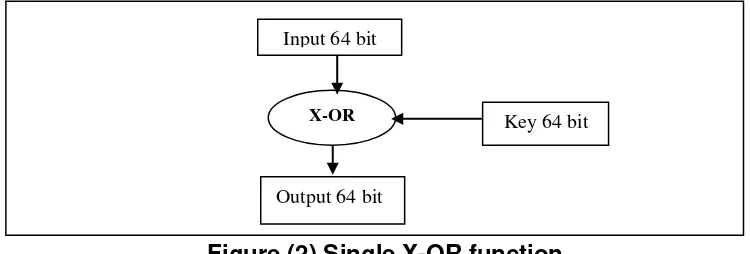
3.4 X-OR function
X-OR function is 64 bits input and output function. The 64-bit inputs are ordered as one-dimensional array, show in figure(2), this array is X-ORed with 64 bits secret key .The input and output have the same size without any change.
The importance of the X-OR function is that, the secret key changes or not changes the input block. Four OR function and 64 bits key for each X-OR are needed, so the total number of the keys bits are (4096 bits) in all the rounds of one block. The secret key is called the X-OR key. The key used in the X-OR function is generated from keys generator, which will be explained later.
Figure (2) Single X-OR function
3.5 Merge function
X-OR Key 64 bit
Input 64 bit
The S-box function is used 256 bits as input, when the outputs from preview stage are 64 bits of each compass function. Must merge outputs of all compasses to make 256 bits. The merge function works that process.
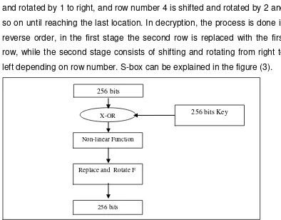
3.6 S-BOX function
S-box function is a 256-bit input and output. The 256 bits input is ordered as 16x16 matrices, the sixteen rows performed in the process to sixteen rows output. The S-Box consists three stages:
First stage : Xoring the original matrix 256 bit with mask S-box, which mask S-box is matrix 256 bit from generator keys
Second stage: Computes the non-linear function for each row by the following algorithm.
Algorithm non-linear function in S-box :
Begin
Convert the bit in position 0
B (j, 0) =a (j, 0) Xor 1 Where j is the row id Put the value of the first location bit in i
i=a (j, 0)
For each k=1 to 16 do Begin
Compute b (j,k)=i Xor 1 Xor a(j,k) Modify i as i=i and a (j,k)
End
Increment the row number (j) and go step 1.
End
In the proposed algorithm, a function with 16-bit input and 16 bit outputs is used for each row.
This non-linear has some properties:
A: The non-linear function designed to be of the same inputs and outputs sizes.
B: The output form this function never results in the same sequence and the output will repeat after 2n
C: Confusion and diffusion: By using the non-linear in |S-box a confusion on the resulting output can be noted, beside, a diffusion will be increased because whenever a zero is located in the sequence the rest of the sequence will be converted.
Third stage: Replace and rotate function
This function replaces the first row with the second row in the first process. In the second process, it shifts and rotates bits from left to right. Shifting and rotating time depends on row number. This process performed from row number 3 to row number 16. Row number 3 is shifted and rotated by 1 to right, and row number 4 is shifted and rotated by 2 and so on until reaching the last location. In decryption, the process is done in reverse order, in the first stage the second row is replaced with the first row, while the second stage consists of shifting and rotating from right to left depending on row number. S-box can be explained in the figure (3).
Figure (3) diagram of S-Box
3.7 Key (session keys) Generator Process
In the proposed algorithm, multi deference keys are needed to use in encryption and decryption. The types of them are:
1. The compass function needs 16 bit key for each part, the total bits in one round 4*16=64,(there are four resulting parts after splitting 256 to 64 bits), and in all rounds the total keys number is 64*16=1024 bits. The same key is used in compass−1 function, in other words, the 16
256 bits
Non-linear Function
Replace and Rotate F
256 bits
bits are used in each part and the part is repeated 16 rounds which equal 256, and because there are four parts the total number is 256*4=1024.
2. The key used with X-ORing in X-OR function is 64 bits key and because there are four parts on X-OR stage, the total number of one round is 256 and the total number of all rounds is 4096 bits.
3. In S-Box stage, a 256-bit plain block X-ORed with mask S-Box, the mask size is 256 bit, for each round and the total number is 256*16=4096 bits.
The total numbers of the using keys are very long, which is difficult to enter by the user, so, a new generator technique is used. This technique uses 64 bits input (secret key are entered by the user) and then generates the remaining keys (replace keys, X-OR keys and mask keys). Those keys will be explained below:
3.7.1 Key schedule
The generator machine of the keys that are used in the algorithm inputs 64 –bits by the user as a secret key and outputs multi keys with different sizes, the machine consists of two parts:
LFSR function.(Linear Feedback Shift Register) Keys generators.
Figure (4) Diagram of LFSR and Key Generator
On the other hand, the output from LFSR function is used as mask S-Box key; the total numbers of mask keys are 16 masks key. In the first round the first output goes to LFSR, in second round only 64 bits are cut from the old mask key and inputs to LFSR to generate new 256 bits and so on until reaching the last round.
3.7.2 LFSR function
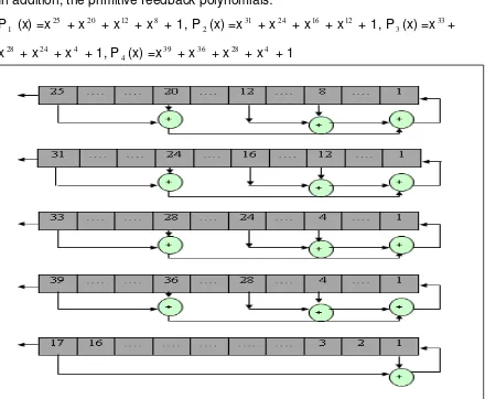
The new design of LFSR function base on stream cipher are present as a new random key generator used to provide 256-bit key for the proposed block cipher algorithm. The design of the key stream generator shown in the following figure consists of (5) linear feedback shift registers (LFSRs),
denoted by LFSR1, LFSR2, LFSR3, LFSR4, and LFSR5 with lengths: L1=25, L2=31, L3=33, L4=39, L5=17
LFSR
Key Generator
16(16 bit)
16(64 bit) Mask (256 bit)
Input 64 bit
Output 256 bit Used only 64 bit
Zt
SR1SR2
SR3
SR5 SR4
Sum
Figure (5) LFSR function
In addition, the primitive feedback polynomials: P1 (x) =x25 + x20 + x12 + x8 + 1, P
2(x) =x
31 + x24 + x16 + x12 + 1, P
3(x) =x 33+
x28 + x24 + x4 + 1, P
4(x) =x
39 + x36 + x28 + x4 + 1
At clock cycle, the LFSRs output bits X i
t , when i=1,2,3,4,5 will added
can explain as integer .The sum of LFSR € {0.1.2.3...,15} is represented in the binary system :
Address=∑ Xi
t A, LFSR functions are explain in the following figure.
Figure (6) LFSRs functions
Algorithm LFSRs Function:
INPUT: 64 Bits (Secret key)
Figure (6) LFSRs functions
OUTPUT: 256 Bits (Master secret key) Begin
For k=1 to 256 do
Begin
For i=1 to number of register do
Begin
Feedback=0.
For j=1 to length of register (i) do
Feed=feed X-or sr(i,st(i,j)).
Shift to left one location. Put feed in first location. Put feed in out array.
End
Out-bit=out(1) X-or out(2) X-or out(3) X-or out(4) Find sum bit from out-bit
Final out (k)=ep(sum) X-or out-bit X-or out(5)
End End
The Proposed algorithm used to generate 256 bit as output, and the input are 64 bit as secret key enter by user ,in addition is used many matrix are used as st and sr ,where st has the parameter of feedback function and
sr presentation of initial values of SR. The output from LFSR functions is random and can test in five test of the randomness tests. A new algorithm has been proposed to generate two types of array keys (compass, X-OR keys), which can be explained in the following figure:
Figure (7) block diagram of Keys Generator
Kay generator function used the output from LFSR as input, arrays generator can be explained in algorithm:
Algorithm Generator Keys:
64-Bit
Split
32 R 32 L
Replace beteen two location Shift to L by number round
64-Bit
Comperssion
16-Bit
16(16-Bit)
INPUT: 64 BIT
OUTPUT: TOW ARRAY ONE DIMANTION X-OR ARRAY 16(16 bit) REPLACE ARRAY 16(16 bit)
For i=1 to 16 do
Begin
1. Split 64 bit to 32L and 32R 2. Shifted left by number round 3. Replace between two locations 4. Merge new 32L and 32R
5. Put new 64 bit in X-OR array in index i 6. Compression 64 bit to 16 bit
7. Put the 16 bit to replace array
8. The output from step 5 goes to step 1
End
After this process the system have are array of replace keys 16(16 bit)and array of X-OR keys 16(64 bit).
4. The Proposed Algorithm Versus DES
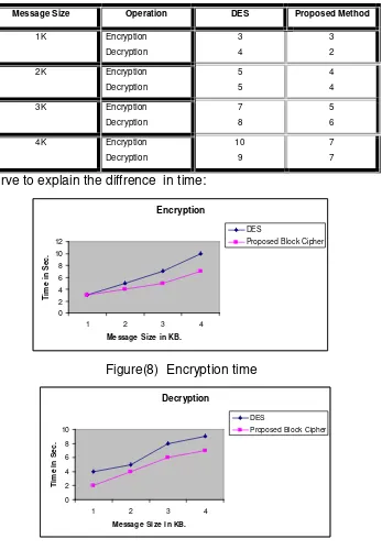
In this part, we will discover some aspects of evaluation concerning speed, complexity and resistance against known attack as a comparative study with DES block cipher system. the speed of the proposed algorithm and DES is non equivalent. The S-box function of DES is an 8-tick time consuming function because there are 8 s-boxes perform serially. In the proposed algorithm, the s-box is take an 1-tick time consuming function because there is 1 S-box perform in parallel-wise each of rows to calculate the output. We are programming these algorithm in Visual basic.Net on P4 with CPU 1.7G.B and RAM 512G.B, then we apply it to massages that have different sizes, we take plaintext of 1K then encrypt it and compute time of running time of its operation, then we take 2K, 3K, and 4Kand compute the running time of encryption and decryption of each message the following table explains the running time in seconds.
Message Size Operation DES Proposed Method
Used curve to explain the diffrence in time:
Encryption
Figure (8) Decryption time
The complexity of any block cipher depends on length key or length block, unless special attack to break through. No publish attack against DES but it is suffering from the weak keys problem. In the DES the length, ok key 56 bits so we need 256trials to find the correct key as brute force attack. In other hand, the complexity for proposed algorithm is 2256 because the key is 256 bits length.
1. The proposed block cipher algorithm enhances two criteria of standard block cipher which are confusion and diffusion.
2. The proposed block cipher algorithm is developed to increase the complexity degree against the attacker task by consuming more time to achieve the analytical process.
3. The proposed block cipher is different in using different initial permutation and final permutations, and using different round permutations, and using different S-box, and using different round content.
4. The proposed algorithm is implemented as a software in terminal devices by simplify the process operations and reduce the consumed time based on partitioning the block itself to achieve the task of multiprocessing and use a new technique in designing the S-Box, because the cost of using hardware is expensive.
5. The proposed block cipher algorithm increases the randomness of the used secret key by expanding the original key through the stream generator which gives higher randomness as a new long secret key with higher randomness property.
References
[1] Rolf O. ,"Contemporary Cryptography", Artech House , Boston ,London,2005.
[2] William S., " Cryptography and Network Security Principles and Practices, Fourth Edition", Prentice Hall, 2005.
[3] Connected: An Internet Encyclopedia. "Block Ciphers". April 1997. Retrieved from http://www.freesoft.org/CIE/Topics/143.htm
[4] “Feistel Cipher”, Wikipedia, the free encyclopedia Retrieved from http://www. Wikipedia .org
[5] Abdulkareem O.Ibadi, "Special Secure E-Mail System" PhD Thesis, University of Technology, 2007