Bulletin for The International Association for Computational Mechanics
N
o
23
June 2008
HeMoLab:
A Computational Framework for
Patient-Specific Modeling of the
Cardiovascular System
Raúl Feijóo
Incorporating Analytic Information in
Computational Schemes
Dan Givoli
PDE-interpolations in Topology
Optimization
Ole Sigmund
Research Activities at the Structural
Mechanics and Coupled Systems
Laboratory
Roger Ohayon
A Break-Through Enhancement of FEM
using Node-based Kriging Interpolation
Worsak Kanok-Nukulchai
APACM - Asia-Pacific
ACMT - Taiwan
USACM - USA
ABMEC - Brazil
GACM - Germany
AMCA - Argentina
ECCOMAS
IACM World Congress
IACM News
IACM Executive Council
President: E.OñateSpainPast Presidents: T.J.R. Hughes U.S.A, J.T. Oden U.S.A.,
A. SamuelssonΥSweden, O.C. ZienkiewiczU.K.
Vice President (Americas): T. BelytschkoU.S.A
Vice President (Asia-Australia):S. ValliappanAustralia
Vice President (Europe-Africa):H. Mang Austria
Secretary General:S. IdelsohnArgentina
Members: A. JamesonU.S.A., W. Kanok-Nukulchai Thailand,
M. KleiberPoland, W.K. LiuU.S.A., R. Owen U.K., E. Ramm Germany,
B. SchreflerItaly, M.W. YuanChina
Corresponding Members: R. de Borst Netherlands, C. Farhat U.S.A.,
J. Fish U.S.A., G.R. Liu Singapore, C. Mota Soares Portugal, R. Ohayon
France, M. PapadrakakisGreece, T. TezduyarU.S.A., T. Yabe Japan
Honorary Members: Y.K. Cheung, China, C.K. Choi Korea,
R. DautrayFrance, E. de Arantes e OliveiraPortugal, T. KawaiJapan,
J. PèriauxFrance, E. SteinGermany, W. WunderlichGermany,
G. YagawaJapan, W. ZhongChina
Honorary Members:
E. AlarconSpain, J. F. BesselingNetherlands, R. DautrayFrance,
C.S. DesaiU.S.A., S.J. FenvesU.S.A., R. GlowinskiU.S.A.
P.K. LarsenNorway, A.R. Mitchell U.K. , J. PériauxFrance, T.H.H. Pian
U.S.A. , O. PironneauFrance, K.S. PisterU.S.A. , L.-X. QianP. R. China
G. StrangU.S.A. , C.W. TowbridgeU. K. , E.L. WilsonU.S.A. , Y. Yamada
Japan , Y. YamamotoJapan , W. ZhongChina, O. C. ZienkiewiczU.K.
O. AllixFrance
T. ArakawaJapan
D. AubryFrance
G. Ayala-MilianMexico
I. BabuskaU.S.A.
G. BakerAustralia
P. Bar-YosephIsrael
F. BasombrioArgentina
K. J. BatheU.S.A.
J-L. BatozFrance
T. BelytschkoU.S.A.
P. BerganNorway
T. BickelU.S.A.
M. BorriItaly
T. BurczynskiPoland
M. CasteleiroSpain
M. Morandi CecchiItaly
M. CerrolazaVenezuela
J. S. ChenU.S.A.
C. K. ChoiKorea
J. Crempien-LaborieChile
E. de Arantes e OliveiraPortugal
R. de BorstNetherlands
L. DemkowiczPoland
M. DoblaréSpain
E. DvorkinArgentina
G. EtseArgentina
R. EwingU.S.A.
C. FarhatU.S.A.
C. FelippaU.S.A.
J. FishU.S.A.
J. FlahertyU.S.A.
K. Fuji Japan
M. GeradinBelgium
M. GilchristIreland
D. GivoliIsrael
J. M. GoicoleaSpain
Y. GuChina
I. HerreraMexico
R. HimenoJapan
A. HuertaSpain
T. HughesU.S.A.
G. HulbertU.S.A.
S. IdelsohnArgentina
K. IshiiJapan
C. JohnsonSweden
T. Kanok-Nukulchai Thailand
K. KashiyamaJapan
J. T. KatsikadelisGreece
M. KawaharaJapan
M. KleiberPoland
V. KompisSlovakia
P. LadevèzeFrance
G. R. LiuSingapore
W. K. LiuU.S.A.
P. LyraBrasil
H. Mang Austria
K. MorganU.K.
C. Mota SoaresPortugal
K. NakahashiJapan
Y. NakasoneJapan
H. Nogushi Japan
A. NoorU.S.A.
J. T. OdenU.S.A.
R. OhayonFrance
Y. OhnishiJapan
E. OñateSpain
J. OrkiszPoland
R. OwenU.K.
M. PapadrakakisGreece
U. PeregoItaly
E. RammGermany
E. RankGermany
B. D. ReddyS. Africa
J. N. ReddyU.S.A.
E. SaccoItaly
A. SamuelssonSweden
K. Sato Japan
B. SchreflerItaly
M. ShephardU.S.A.
P. SteinmannGermany
B. SzaboU.S.A.
H. TakedaJapan
N. TakeuchiJapan
T. TaniguchiJapan
R. TaylorU.S.A.
J. A. Teixeira de FreitasPortugal
T. TezduyarU.S.A.
A. TezukaJapan
S. ValliappanAustralia
N. VrankovicCroatia
W. WallGermany
T. WatanabeJapan
J. WhitemanU.K.
N.-E. WibergSweden
B. WohlmuthGermany
P. WriggersGermany
T. YabeJapan
G. YagawaJapan
S. YoshimuraJapan
S-K. Youn Korea
M. YuanChina
K. YugeJapan
Y. ZhengChina
IACM Membership
FeeThe annual fee for direct individual membership of IACM is 25 US dollars.
For affiliated organisations the membership fee is 10 dollars per member. The Bulletin and a discount on IACM supported activities (congress, seminars, etc.) are some of the benefits of the membership. For further details contact IACM Secretariat.
IACM Expressions
Published byThe International Association for Computational Mechanics (IACM)
Editorial Address
IACM Secretariat, Edificio C1, Campus Norte UPC, Gran Capitán s/n, 08034 Barcelona, Spain. Tel: (34) 93 - 401 7441, Fax: (34) 93 - 401 6517,
Email: [email protected] Web: www.iacm.info
Editorial Board
E. Dvorkin - South America M. Kawahara - Asia-Australia
E. Oñate - Europe W.K. Liu - North America Production Manager
Diane Duffett Email: [email protected]
Advertising
For details please contact Diane Duffett at the IACM Secretariat.
IACM members are invited to send their contributions to the editors. Views expressed in the contributed articles are not necessarily those of the IACM.
IACM Affiliated Organisations
Listed in order of affiliation
U.S.A. U.S. Association for Computational Mechanics (USACM)
Argentina Asociacion Argentina de Mecanica Computacional (AMCA)
PR China The Chinese Association of Computational Mechanics
Italy Gruppo Italiano di Meccanica Computazionale (GIMC)
Denmark, Estonia, Finland, Iceland, Latvia, Lithuania, Norway, Sweden
The Nordic Association for Computational Mechanics (NoACM)
Japan The Japan Society for Computational Engineering and Science (JSCES)
Spain Sociedad Española de Métodos Numéricos en Ingeniería (SEMNI)
Germany German Association of Computational Mechanics (GACM)
France Computational Structural Mechanics Association (CSMA)
U.K. Association for Computer Methods in Engineering (ACME)
Greece The Greek Association of Computational Mechanics (GRACM)
Austria, Croatia, Hungary, Poland, Slovenia, The Czech Republic, Slovakia
The Central-European Association for Computational Mechanics (CEACM)
Poland Polish Association for Computational Mechanics
Bulgaria The Bulgarian Association of Computational Mechanics (BACM)
Chile Asociacion Chilene de Mecanica Computacional (SCMA)
Israel The Israel Association of Computational Methods in Mechanics (IACMM)
Portugal The Portuguese Society of Theoretical, Applied and Computational Mechanics
Australia Australian Association of Computational Mechanics
S. Africa South African Association for Theoretical and Applied Mechanics (SAAM)
Turkey Turkish Committee on Computational Mechanics
Brazil Brazillian Association for Computational Methods in Engineering (ABMEC)
VenezuelaSociedad Venezolana de Métodos Numéricos en Ingeníera
Romania Romanian Association for Computational Mechanics
Mexico Sociedad Mexicana de Métodos Numéricos en Ingeniería
Ireland Irish Society of Scientific and Engineering Computations (ISSEC)
Korea Korean Association on Computational Mechanics (KACM)
Thailand Thailand Society for Computational Mechanics (TSCM)
SingaporeSingapore Association for Computational Mechanics (SACM)
India Indian Association for Computational Mechanics
Japan Japanese Association for Computational Mechanics (JACM)
Netherlands Netherlands Mechanics Committee (NMC)
Malaysia Malaysian Association for Computational Mechanics (MACM)
Serbia Serbian Association for Computational Mechanics (SACM)
Taiwan Association for Computational Mechanics Taiwan
contents
This activity shows that the health of the Computational Mechanics community is good. Perspectives for 2009 are equally optimistic as some 20 Thematic Conferences in the field of computational engineering and sciences will take place in Europe under the auspices of ECCOMAS. In addition many regional and national conferences in compu-tational mechanics will be held in USA, Spain, Portugal, Germany, France, Nordic Countries in Europe, Argentina, Brazil, etc. Of particular interest is the 1st African
Conference in Computational Mechanics to be held in Sun City, South Africa on 7-10 January 2009. I hope that this event will be followed by many others helping to develop the activities of IACM in Africa.
What’s next?
Despite the success of IACM activity worldwide we should perhaps meditate on the relative impact and influence of computational mechanics on the key areas in science and technology and act consequently. The web give us a good hint. A quick browse over the number of entries in Google gives the following result: computer science, 68.5 millions; material science, 36 millions; CAD (computer aided design), 14.6 millions; nano technology, 12.7 millions; numerical methods, 7.3 millions; numerical methods in engineering, 3.1 millions and computational mechanics, 1.5 millions!. Numbers speak for themselves. The conclusion of this arguable exercise is that the IACM community should move forward with an instinct to increase its impact and influence in traditional and emerging areas in engineering and sci-ences. Indeed the size and scope of the Venice congress is a sign that we are moving in a good direction.
Best wishes for a successful WCCM/ECCOMAS 2008 congress.
Eugenio Oñate President of IACM
editorial
This issue of IACM Expressions will come to light coincidingwith the celebration of the joint WCCM/ECCOMAS congress to be held in Venice from June 30th to July 4th 2008. The congress merges the 7thedition of the World Congress on
Computational Mechanics of the IACM and the 5th European Congress on Computational Methods in Applied Sciences and Engineering of ECCOMAS, the European organization that groups all the IACM affiliated associations in Europe. The success of this joint venture is clearly shown by the number of close to 3000 participants, a landmark in the history of past IACM and ECCOMAS congresses. Some 170 Minisimposia have been organised by leading experts in topics covering most disciplines in computational science and engineering, ranging from fundamental and emerging areas in computational mechanics, such as nano-mechanics and material modelling, to innovative industrial applications in aeronautics, forming processes, civil engineering and bio-medical engineering, among many others. I want to take this opportunity to thank the congress organisers Profs. Bernard Schrefler and Umberto Perego and their teams at Universities of Padua and Milan for an excellent and outstanding work.
Certainly the idea to merge the World Congress of Computational Mechanics of the IACM with congresses in the same field held in different regions of the world enlarges the scope and impact of the joint congress. This model was successfully implemented for the first time in Beijing in 2004 where the 5thWCCM was merged with the Asian-Pacific
Congress on Computational Mechanics (APCOM). Following the Venice venue the next joint WCCM/APCOM congress will be held in the city of Sydney in Australia on 19-23 July 2010. This will be an opportunity to gather the computational mechanics community from the Asian-Pacific region with colleagues from the rest of the world. Indeed beating the number of participants in Venice will be a chal-lenge for future editions of WCCM. Our colleagues in Sydney, lead by Profs. S. Valliappan and M. Khalili, will be the first to try. Best of luck to WCCM/APCOM 2010!.
HeMoLab: A Computational Framework for Patient-Specific Modeling of the Cardiovascular System
Raúl Feijóo
Incorporating Analytic Information in Computational Schemes
Dan Givoli
PDE-interpolations in Topology Optimization
Ole Sigmund
Research Activities at the Structural Mechanics and Coupled Systems Laboratory
Roger Ohayon
A Break-Through Enhancement of FEM using Node-based Kriging Interpolation
Worsak Kanok-Nukulchai
APACM - Asia-Pacific
ACMT - Taiwan
USACM - USA
ABMEC - Brazil
GACM - Germany
AMCA - Argentina
ECCOMAS
IACM World Congress
IACM News
Conference Diary
4
10
16
21
26
by
Raúl Feijóo
Laboratório Nacional de
Computação Científica
Petrópolis
Brazil
HeMoLab: A Computational Framework
for
Patient-Specific Modeling
of the
Cardiovascular System
1. Introduction
Over the last few years, predictive com-putational tools have been introduced in medical practice as a result of joint research on areas of engineering, biology and medicine. The current state of devel-opment reached by techniques of compu-tational modeling, together with the fast increase in the performance of computer hardware, has produced highly sophisti-cated models with acceptable levels of predictive capability. Computational mod-eling and simulation techniques, in con-junction with graphic visualization and vir-tual reality provide high-resolution three-dimensional images representing the phenomena occurring at specific parts of the human body.
It is worth mentioning that cardiovascular diseases (CVD) are and will continue to be the main cause of human death throughout the world including develop-ing countries such as Brazil where the social impact of the CVD’s becomes more relevant due to the fact that they are the main cause of early retirement on health grounds and the second reason for in-patient treatment admissions.
The important consequences of such dis-eases at the individual and social levels, together with the recognition that several CVD’s are closely linked to hemodynam-ic factors, have motivated an increasing interest in the use of computational simu-lation techniques in order to gain better knowledge of the cardiovascular system. Thus, the development of accurate com-puter models is crucial to attain a better understanding of the cardiovascular sys-tem under normal conditions and under conditions altered either by vascular reconstruction or by surgical procedures in general.
This emerging technology, consisting of modeling - computer simulation, soft-ware and hardsoft-ware, is contributing to the development of patient-specific mod-els so that accurate analyses of the
dynamics of the cardiovascular system can be carried out. It also allows the mod-eling of absorption, diffusion and trans-port phenomena to take place in arterial wall tissue and can be used in medical training, improvement of surgical tech-niques and several medical procedures planning as well. Such techniques allow, in addition, the characterization (in a non-invasive manner) of in- vivo properties of biological materials needed in the com-putational modeling.
However, the benefits that computational modeling could bring to vascular medi-cine depends on overcoming a number of barriers. The first challenge consists of the development of computational mod-els with the required level of complexity to accurately represent hemodynamic aspects of the most relevant parts of the cardiovascular system. The second chal-lenge stems from the need to develop computational tools capable of character-izing geometrical and mechanical proper-ties of the system with information obtained from different medical image acquisition systems. The third challenge is the difficulty in setting appropriate boundary conditions in highly sophisticat-ed models. Examples of this are: the determination of coupling equations in a 1D-3D model, the determination of appropriate coefficients for Windkessel type terminals that allow the modeling of the peripheral beds not included in the analysis or its substitution by arterial beds built with optimization methods. The fourth challenge is related to the approximation of such models which require the solution of systems of millions of non-linear equations at each time inter-val and must be coupled to techniques that allow the adaptive analysis of the problem so as to keep the analysis error within prescribed bounds. Finally, the sheer amount of data generated in such analyses requires the development of efficient tools for the storage and retrieval of clinically relevant information as well as for the visualization and real-time high resolution representations of easy
“... the development
of accurate
computer models
is crucial to
attain a better
understanding of
the cardiovascular
system under
normal conditions and
under conditions altered
either by vascular
reconstruction or by
surgical procedures in
is also involved in the development of human resources, and to this end it is closely connected with the LNCC’s multi-disciplinary pos-graduation program, from which several DSc. students are active participants. Several other coop-eration agreements are part of this pro-ject with the following institutions: Instituto do Coração Edson Saad of the University Hospital Clementino Fraga Filho of the Federal University of Rio de Janeiro, Brazil; Instituto do Coração of the Clinical Hospital of the School of Medicine of the São Paulo Sate University, Brazil; National University of Mar del Plata, Argentina; Centro Atómico Bariloche, Argentina; National University of the Center of Buenos Aires, Argentina; Pompeu Fabra University, Spain and the Civil and Computational Engineering Centre of the Swansea University, UK.
3. Development environment
The HeMoLab System is developed on top of the Paraview architecture [1], which is an open-source application based on the VTK library. The HeMoLab is developed in ANSI–C++ and exploits OpenGL rendering primitives. Paraview works with filters ordered as a pipeline pattern. This philosophy allows for easy user interactivity and facilitates the data processing in view of the automatism of the process. Paraview was also chosen because it supports distributed data pro-cessing/ rendering as well as its portabil-ity. Thus, the HeMoLab can be under-stood as a customization of the Paraview software that incorporates a series of fil-ters in order to assemble a software ori-ented for patient-specific modeling of the cardiovascular system.
interpretation by clinicians, surgeons and all involved in the assessment of the problem.
On the other hand, the development of models of this type and their use in com-puter simulations requires multi- discipli-nary teams with high level of competence in their respective areas. For example, the computer simulation of the human cardiovascular system requires special-ists in areas such as medicine, biology, chemistry, continuum mechanics, solid and fluid mechanics, variational methods, approximation methods (the Finite Element Method, for instance), high per-formance computing, adaptive methods, image processing and visualization, auto-matic mesh generation, among several others.
2. The HeMoLab Project
In order to attend the above paradigm, the HeMoLab Project was initiated in Brazil in 2005. The main objective of this project was the modeling and computa-tional simulation of the cardiovascular system. The scientific and technological innovations generated within this project (HeMoLab System) will be transferred to the medical community in Brazil in the expectation that the patient-specific com-putational simulation of the cardiovascu-lar system will contribute to the develop-ment of new, and more adequate, treat-ments to improve life quality by providing auxiliary tools for analysis.
The core of the HeMoLab Project is car-ried out within the National Laboratory for Scientific Computation (LNCC/MCT, Petrópolis, Brazil, www.lncc.br/prjhemo), and makes use of the computational infrastructure available there. The project
“ ... a customization of
the Paraview software
that incorporates a
series of filters in order
to assemble a software
oriented for
patient-specific modeling of the
cardiovascular system.”
(a) (b)
4. 1. 1D Model Module
With this module it is possible to handle in a totally arbitrary fashion the creation and edition of seg-ments and terminals to give rise to the topology of the arterial system. Tools to alter geometrical and mechanical proper-ties of the segments and elements or even to modify the data that characterize the peripheral beds are given. A param-etrized curve to represent the heart inflow boundary condition is also available
(fig-ure 1 (a)). The last step before the simu-lation is the configuration of the parame-ters of the mathematical formulation. Also, the visualization of results coming from 1D simulations is comprised in this module, and it can be carried out simply by picking the points of interest over the segments (figure 1 (b)).
4. 2. Image Processing Module
The goal of this module is to segmentate a certain medical image (a set of DICOM images as in figure 2) in order to create an initial mesh that will be used by the 3D Model module. Proper readers are avail-able to give support to several formats, and then numerous methodologies are implemented such as noise reduction,
4. The HeMoLab framework
The HeMoLab software is prepared to deal, in an integrated manner, with several tasks arisen from the cardiovascular modeling.
These are:
i medical image processing including segmentation, geometry characterization and finite element mesh generation,
ii simplified blood flow simulation via 1D models,
iii complex blood flow simulation via 3D models,
iv coupled blood flow simulations via 3D-1D models and
v visualization: 1D and 3D data post-processing.
Within the HeMoLab there are five mod-ules embedded that conveniently group the aforementioned tasks, and also an specific module that takes care of the numerical simulation, these are:
- 1D Model Module
- Image Processing Module - 3D Model Module
- 3D-1D Coupling Module - Visualization Module - SolverGP Module
A brief explanation about the incumben-cies of each component is given in what follows.
Figure 2
Figure 3
Figure 4 (a) (b)
Figure 6 (a) (b)
smoothing and threshold filters among others. Finally, segmentation techniques using classical concepts and novel ones (such as the use of the topological deriv-ative) are also implemented.
4. 3. 3D Model Module
This module is fed with an initial geome-try coming from the Image Processing module. Thus, its main task is divided into two steps:
i the surface mesh generation and ii the volume mesh generation.
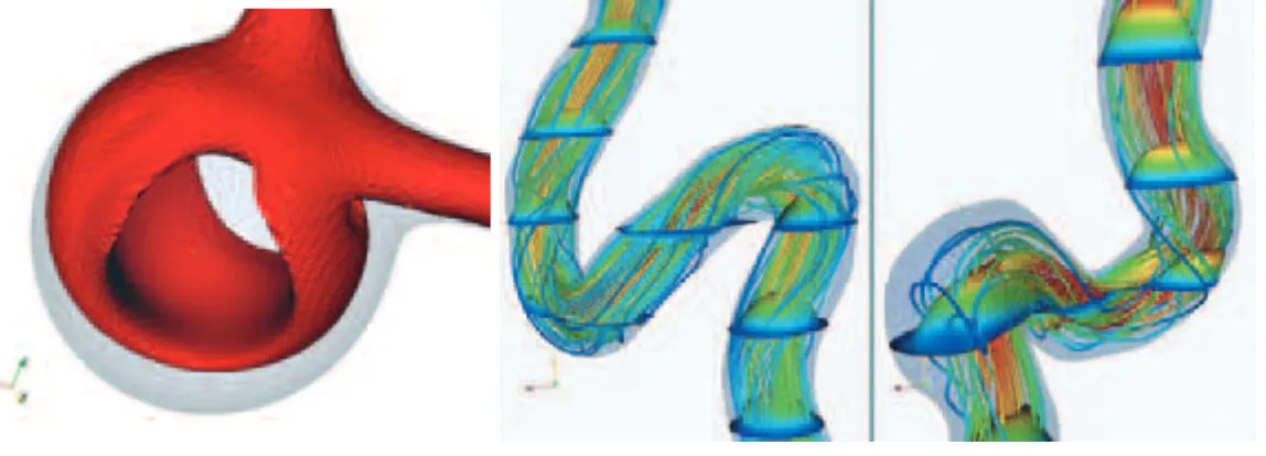
The first step comprises several tech-niques to add and remove nodes and ele-ments, and also to handle the different groups of elements in order to character-ize properly the arterial wall and the inlets/outlets of the domain of analysis. Once the surface mesh is ready, a Delaunay method is used to mesh the volume. In the case of figure 3 the final mesh has 728.200 nodes, 102.500 sur-face elements (triangles) and 4.235.800 volume elements (tetrahedra). The last step is to set boundary conditions to the inlets/outlets choosing between time-varying or stationary Dirichlet and/or Neumann boundary conditions. The wall must also be characterized through the geometrical and mechanical properties. It is also possible to develop models altered artificially by adding an anomaly in the geometry. In figure 4(a)it is shown an artificially created aneurysm, while in
figure 4(b)the opposite situation, a steno-sis, is simulated by removing part of the geometry.
4. 4. 3D-1D Coupling Module
With 1D and 3D mod-els at hand, HeMoLab allows also their cou-pling in order to obtain a more complex model whose purpose is to get rid of bound-ary conditions over the 3D model (now the boundary condi-tions are the heart ejection and the peripheral
impedance). Coupling multidimensional models is a relatively novel approach [2] that permits modeling a more wide range of physical situations such as the sensi-tivity of the cardiac pulse to the presence of a pathology, for instance aneurysms or stenoses, or even to assess how the blood flow changes in an arterial district when the cardiac rhythm is accelerated. The preparation of a coupled model involves three stages:
i the selection of a 1D model, ii the selection of an arbitrary number
of 3D models and
iii determining the relations between the points in the 1D model that have to be related to the inlets/outlets of the 3D districts.
Figure 5 shows how this task is done in a very interactive way selecting the cor-responding objects (one point + one coupling surface) that perform the cou-pling. Finally, all the complementary con-figurations concerning the mathematical formulation have to be set before carrying out the simulation.
4. 5. Visualization Module
This module makes use of the more com-mon native Paraview filters to process, in this case, finite element data. Several classical filters are given such as glyph, iso-surface, streamline or calculator fil-ters. Figure 6(a)presents the streamlines and iso-surface of blood flow in an aneurysm artificially introduced in the internal carotid artery, while figure 6(b)
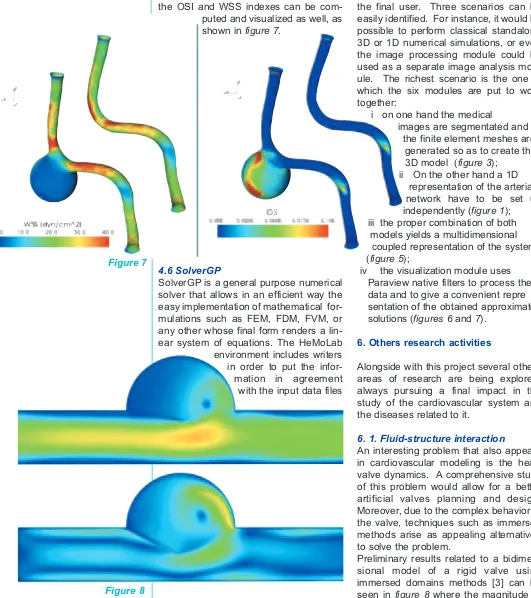
presents also the warping of the velocity field in the vertebral arteries. Since they are useful in hemodynamic simulations the OSI and WSS indexes can be com-puted and visualized as well, as shown in figure 7.
4.6 SolverGP
SolverGP is a general purpose numerical solver that allows in an efficient way the easy implementation of mathematical for-mulations such as FEM, FDM, FVM, or any other whose final form renders a lin-ear system of equations. The HeMoLab environment includes writers in order to put the infor-mation in agreement with the input data files
to be sent to the SolverGP module. Once the numerical simulation is finished the output is returned back to the HeMoLab so as to retrieve the data of interest from the simulation. SolverGP supports dis-tributed computing via the PETSc library for the resolution of the final linear sys-tems of equations.
5. Available scenarios
The HeMoLab usage can be combined in several ways according to the interest of the final user. Three scenarios can be easily identified. For instance, it would be possible to perform classical standalone 3D or 1D numerical simulations, or even the image processing module could be used as a separate image analysis mod-ule. The richest scenario is the one in which the six modules are put to work together:
i on one hand the medical
images are segmentated and the finite element meshes are
generated so as to create the 3D model (figure 3);
ii On the other hand a 1D representation of the arte rial network have to be set up independently (figure 1); iii the proper combination of both
models yields a multidimensional coupled representation of the system (figure 5);
iv the visualization module uses Paraview native filters to process the data and to give a convenient repre sentation of the obtained approximate solutions (figures 6 and 7).
6. Others research activities
Alongside with this project several others areas of research are being explored, always pursuing a final impact in the study of the cardiovascular system and the diseases related to it.
6. 1. Fluid-structure interaction
An interesting problem that also appears in cardiovascular modeling is the heart valve dynamics. A comprehensive study of this problem would allow for a better artificial valves planning and design. Moreover, due to the complex behavior of the valve, techniques such as immersed methods arise as appealing alternatives to solve the problem.
Preliminary results related to a bidimen-sional model of a rigid valve using immersed domains methods [3] can be seen in figure 8 where the magnitude of
Figure 7
the velocity field is shown. It is projected that the HeMoLab embraces a
module for fluid-structure analysis using immersed concepts during the present year. This tool will definitely makes research faster.
6. 2. Multiscale modeling
It is well-known that the con-stitutive response of the
arterial wall is rather complex, and that such behavior escapes to the predictive capabilities of classical phenomenological models. In this regard, multiscale models based on variational principles [4] provide an insightful way to tackle the problem. For instance, through an assemblage of elastin and collagen (figure 9with a com-bination of a hyperelastic matrix and bars) a typical constitutive response can be obtained. (also
figure 9).
This kind of technique provides power-ful tools in order to study arterial wall behavior, and is likely to be included in the short term within the HeMoLab system as a complemen-tary module.
6. 3. Other areas
Others areas of research are under development in our multidisciplinary team. Among them we mention two: i image processing, an area that is continuously evolving in order to ensure a more accurate geometry characterization of the arterial districts under investigation, and ii identification and material
properties characterization of biological tissues.
In particular, this last issue is being tackled in the HeMoLab Project by means of the topological derivative. Preliminary results of location of an inclusion in a given domain from measurements are shown in figures 10(a) and10(b)for one and two inclusions respectively.
Bibliography
[1]. Kitware and Sandia National Laboratories. Paraview – Kitware Inc. http://www.paraview.org.
[2]. P.J. Blanco, R.A. Feijóo and S.A. Urquiza, A unified variational approach for coupling 3D-1D models and its blood flow applications, Comp. Meth. Appl. Mech. Engrg., (196) 4391-4410, 2007.
[3] P.J. Blanco, R.A. Feijóo and E.A. Dari, A variational framework for fluid-solid interaction problems based on immersed domains. Theoretical bases.To be published in Comp. Meth. Appl. Mech. Engrg.
[4] E.A. de Souza Neto and R.A. Feijóo, Variational foundations of multi-scale constitutive models of solid: Small and large strain kinematical formulation.LNCC Research & Development Report 16/2006, Brazil: National Laboratory for Scientific Computing.
Figure 9
Figure 10 (a)
I
remember my excitement, as a young graduate student almost 25 years ago, when I started to understand the insides of the finite element method (FEM) for the first time and realized how general it was. In fact I was a bit carried away. My early impres-sion was that I can takeanygiven partial dif-ferential equation (PDE) or system of PDEs and apply the standard Galerkin FEM to it, generate a mesh with a few thousands degrees of freedom, and voilá, I get a per-fect numerical solution! It took me some time to discover that while this procedure can technically be followed, in various important situations it does not yield satis-factory numerical results. Moreover, I later realized that this difficulty was not associat-ed only with the Galerkin FEM; the more general observation is that there exist cases for which standard numerical treatment fails and special measures are needed in order to obtain good accuracy with manageable computational effort.One possible approach for tackling prob-lems whose naive treatment fails is to make use of analytic informationavailable on the behavior of their solution. The present article is concerned with this methodology. In what follows we briefly survey a few methods which have been developed for computa-tional mechanics and that incorporate spe-cial “inside knowledge” on the exact solu-tion. These should be contrasted with meth-ods of brute-force numerics (which are also very useful many times!).
Trefftz Methods
Perhaps the most direct way in which ana-lytic information is incorporated into a com-putational scheme is that employed in Trefftz methods. Erich Trefftz (1888-1937)
(Figure 2) was a German mathematician who invented a numerical methodology now called by his name. See a short biography of Trefftz and comments on his work in [1]. His famous paper on the “Trefftz method” was published in 1926 [2]. Later this approach was recognized as general and powerful, and was extended in various ways. See, e.g., the new book on the sub-ject [3], and the review papers [4,5]. See also the article on the Trefftz method in a previous issue of IACM Expressions [6].
The key ingredient in the Trefftz method is the fact that the solution of the problem is
approximated by a superposition of func-tions satisfying the governing PDEs exactly. This is in contrast to the standard Galerkin FEM, where simple polynomial functions are used in each element. Depending on the specific version of the Trefftz method used, some of the boundary conditions may also be satisfied a prioriby these functions. The unknown coefficients in the Trefftz expansion are determined so as to approxi-mately satisfy all the remaining boundary conditions. The precise way in which this is done depends on the specific Trefftz method employed: by collocation, by least squares, by the Galerkin mechanism, etc. See, e.g., the recent paper [7] for a compar-ison between two popular Trefftz-type meth-ods (the Ultraweak Variational Formulation and the Least-Squares Method) for short wave problems.
Figure 1:
Computational Hybridization of Inside Knowledge and Numerics (CHIKN) versus Brute Force (BF) numerics.
by
Dan Givoli
Technion
Israel Institute of
Technology
Israel
I
ncorporating
A
nalytic
I
nformation
in
C
omputational
S
chemes
“The key
ingredient ... is the fact
that the solution of the
problem is
approximat-ed by a superposition
of functions satisfying
ties such as those at crack tips and at reen-trant corners.
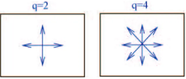
We elaborate a little on short wave applica-tions. Suppose we want to solve the Helmholtz (reduced wave) equation with a very large wave number, namely for very short waves. In standard FEM we would have to use an extremely fine mesh to resolve the solution. A well-known rule of thumb claims that one should use 10 ele-ments per wave-length, but in fact a much finer resolution would typically be required in order to overcome numerical dispersion (pollution) errors. This fact makes standard FEM computation for short waves totally impractical. By constructing a space of ``plane-wave functions’’ with the appropriate wave-length, PUM can be used to solve such problem with a reasonably crude mesh. Laghrouche and Bettess [10] seem to be the first to implement PUM for two-dimensional short-wave problems. Their finite element spaces with two plane-wave functions and four plane-wave functions are illustrated in Fig.3.
In 2000, the idea of PUM led in a natural way to the so-called Generalized FEM (GFEM) [11] which combines the standard FEM and PUM. Thus, the GFEM space includes both the piecewise-polynomials and the special functions which carry ana-lytical information on the solution. In the con-text of short-wave analysis, the role of the special (PUM-based) functions is to repre-sent the fast variation in the computational solution, whereas the traditional polynomi-als reduce the error associated with the slow variation.
Figure 3:
Illustration of the basis functions used in PUM for a short-wave problem: two plane waves (q=2) and four plane waves (q=4)
Figure 2: Erich Trefftz
Trefftz methods can also be categorized into direct and indirect ones, and are related to the direct and indirect boundary element (BE) formulations. However, whereas BE formulations are based on the associated free-space Green’s function, which is singu-lar, the fundamental functions used as the basis for the Trefftz method are completely regular and are thus more convenient to compute with. As a single example, for the two-dimensional Laplace’s equation one may use the sequence of Trefftz functions Tn = rnein2, where (r,2) are the polar
coordi-nates. On the other hand, the free-space Green’s function in this case is G= (log r) / (2B), which possesses a logarithmic
singu-larity. Incidentally, one may view the BE method too as a method which incorporates analytical information, i.e., the Green’s func-tion. However, the use of analytic informa-tion in the Trefftz formulainforma-tion is more direct.
A difficulty that is often associated with Trefftz methods is the ill-conditioningof the discrete system of equations. Interestingly, ill-conditioning is typical to most of the meth-ods surveyed here that incorporate analytic information. For Trefftz methods, various remedies have been proposed to overcome this difficulty; see the review papers men-tioned above.
Partition of Unity and Space Enrichment Methods
singulari-GFEM belongs to a class of methods that may be called space enrichment methods. In these methods the usual finite-element space is enriched by additional functions which represent the characteristics of the exact solution behavior. In recent years, various space enrichment methods have been proposed. We mention the
Discontinuous Enrichment Method (DEM) [12] for short waves, in which the finite ele-ment space is enriched with discontinuous functions, and continuity across element interfaces is enforced weakly via Lagrange multipliers. One important advantage of DEM over some other space-enrichment methods is the relatively well-conditioned stiffness matrices that it produces. We also mention the method of Residual-Free Bubbles [13] which also constructs element shape functions with favourable properties based on an element-level analytic solution.
The eXtended Finite Element Method (XFEM)
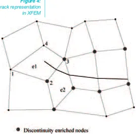
Belytschko and his group developed the eXtended Finite Element Method (XFEM) starting from 1999; [14,15], although the name XFEM was coined only later. XFEM is intended to treat discontinuitiesof various kinds which appear in the problem and whose geometry does not coincide with that of the finite element mesh. One important example is the treatment of cracks. In prob-lems involving crack growth or a large amount of static cracks, it is very inconve-nient and inefficient to generate a boundary-fitted mesh. XFEM allows the treatment of
Figure 4: Crack representation
in XFEM
discontinuities (e.g., cracks) that pass through the mesh lines. See Figure 4 for such a configuration in two dimensions. XFEM is a space-enrichment method. It is in fact a special case o GFEM; however it involves a large amount of specialized tech-niques for the treatment of the discontinu-ities (related to the construction of the shape functions, the numerical integration, etc.), that justify a separate categorization. For a crack, the element space is equipped with the standard polynomials and by two types of enrichment functions: those that repre-sent the jump in the solution across the dis-continuity, and those that represent the crack-tip singularity. See the review of XFEM by Moës in a recent IACM Expressions issue [16].
Combination of Asymptotic and Numerical Methods
It is well known that the regimes where asymptotic methods on one hand and numerical methods on the other hand are at their best are typically different. The appear-ance of a small parameter in the problem is a blessing for asymptotics but may be a bane for numerics. As an example, the appearance of a thin boundary layer makes numerical treatment difficult, while under some simplifying conditions asymptotic treatment may be straight forward. Short wave scattering is another case in point; as indicated above standard numerical treat-ment is difficult, while there are powerful asymptotic methods for such problems based on ray tracing, although they usually assume simple geometry. Various methods have been proposed which combine a
dard numerical method and an asymptotic method in order to get the best of both worlds. For boundary layer problems, a method combining asymptotics and finite elements was devised by Bar-Yoseph and Israeli [17]. The method was applied to two-dimensional diffusion-convection equations and to non-linear similarity equations, and was later extended to other equations and configurations.
A `hybrid numerical asymptotic method’ was devised by Giladi and Keller [18] for short wave scattering. In this method, geometri-cal theory of diffraction is used to provide asymptotic solutions which are sums of products of rapidly oscillating phase factors and slowly varying amplitude factors. The phase factors are determined by ray tracing, while the amplitude factors are found by the Galerkin FEM but using shape functions which are derived asymptotically. This com-bination is illustrated in Figure 5for scatter-ing from a parabolic surface.
Another method for combining ray tracing and FEM was proposed by Barbone at el. [19]. The method is based on patching, on an artificial boundary, a short wavelength asymptotic expansion of the ‘outer’ field to a FEM interpolation of the ‘inner’ field. Continuity of the field and its normal deriva-tive across the artificial boundary is enforced weakly in a variational setting. Coupling of ray tracing and boundary elements was pro-posed very recently by Hampel et al. [20].
In the context of nonlinear analysis of elas-tic structures, the group of Potier-Ferry has constructed powerful combined asymptotic-numerical methods. The asymptotics helps in reducing the problem to one which is much more tractable numerically. See, e.g.,
[21] for a method of computing bifurcating branches (e.g., postbuckling of shells), and [22] for a more recent asymptotic-numerical method for unilateral contact.
Homogenization is often employed when solving problems involving composite mate-rials and structures, as a way to represent the small scales (associated with the fast variation of material properties) in a compu-tationally manageable way. Various meth-ods have been proposed which make use of asymptotics to incorporate the homogeniza-tion in the computahomogeniza-tional scheme itself. Much work in this direction has been done by Fish’s group; see, e.g., the very recent paper [23].
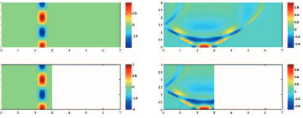
DtN and Absorbing Boundary Conditions
The Dirichlet-to-Neumann (DtN) FEM was devised [24] for problems in unbounded domains, as typical in geophysics, oceanog-raphy, acoustics, etc. The method compris-es the following steps: (a) introduce an arti-ficial boundary B which encloses a finite computational domain Ω(the region of inter-est), (b) solve the problem analyticallyin the exterior domain, (c) use the analytic infor-mation to construct an exact boundary con-dition on B, called the DtN boundary condi-tion, and (d) solve the problem by FEM in Ω. The method was used initially to solve var-ious elliptic infinite-domain problems, and especially time-harmonic wave scattering problems. Later the DtN method was extended to other configurations, including those which involve geometrical singulari-ties (like cracks) in a bounded domain. See, e.g., the review paper [25].
Figure 6:
Use of the high-order Hagstrom-Warburton Absorbing Boundary Condition (ABC), for a dispersive non-homogeneous medium.
“Various
methods have been
proposed which combine
a standard
A closely related class of schemes for wave problems in unbounded domains are those incorporating Absorbing Boundary Conditions (ABCs). The DtN boundary con-dition is a nonlocal ABC, but local ABCs strongly based on analytic information can also be constructed. Their main advantage is that they are readily applicable to time-dependent problems. Recently, Hagstrom et al. [26] proposed high-order ABCs (which are extended versions of the Hagstrom-Warburton ABCs [27]) for some complicated configurations in wave-guides. Figure 6
shows results generated by this method. The medium is dispersive and its material wave-speed varies linearly in the cross-sec-tion of the guide. Plotted are color-map snapshots of the computed solution in the truncated domain (lower plot) and of a refer-ence solution in a long domain (upper plot), at times (a)t = 0 and (b) t = 1.096. It is
apparent that the agreement between the computed and reference
solutions is excellent and no spurious reflec-tions are visible.
Variational Multiscale (VMS) Methods
The Variational Multiscale (VMS) method was invented in 1995, when Hughes pub-lished the seminal paper [28]. Since then various applications and extensions have been proposed by many authors; see, e.g., [29, 30]. The method addresses the com-mon situation when the sought exact solu-tion consists of (at least) two scales: a
resolvablescale, namely a scale which can be resolved by the computational mesh used, and an unresolvable or sub-grid
scale. See the illustration in Figure 7. We cannot simply ignore the sub-grid scale, even if we are only interested in the coarse-scale behavior; due to the coupling that exists among the different scales of the
problem, the fine scale affects the coarse scale. The challenge is to obtain an accu-rate solution with a finite-element mesh that can resolve only the coarse scale.
The basic VMS method can be summarized by the following steps: (a) decompose the solution in the form u = 6u + u´ where6u is the resolvable-scale solution and u´ is the subgrid scale solution, (b) write u´as driven by the residual of the resolved scale, and express u´analytically on each element in terms of 6u , and (c) use the expression obtained for u´to eliminate from the weak form of the problem the explicit dependence on the subgrid scale. All this results in a weak formulation in which the subgrid scale
u´does not appear explicitly. Thus, the VMS method leads to a variational formulation which is an improved version of the stan-dard variational formulation in that it
implicit-ly includes the relevant (analytic) informa-tion associated with the unresolved scales.
In addition to the ability of the VMS method to solve multiscale problems very effective-ly, it entails great theoretical importance in that it sheds light and provides a strong basis to seemingly different types of meth-ods such as bubble-enriched methmeth-ods (such as RFB [13]) and stabilized methods.
Figure 7: An illustration of a typical multiscale solution (left), its resolvable scale (middle)
and its unresolvable (subgrid) scale.
“When I bet
without much a priori
knowledge
I lose on average 80%
of my bets.
But if I bet after
gathering a lot of
information on
the horses and the
jockeys, finding
out about their
known applied mathematician Julian Cole (1925—1999) once told me over lunch in RPI, regarding his experience in horse-race betting at near-by Saratoga:
“When I bet without much a priori knowl-edge I lose on average 80% of my bets. But if I bet after gathering a lot of infor-mation on the horses and the jockeys, finding out about their success records, etc., I lose even more.’’
I hope that this has no analogy to the type of methods reviewed here!
Additional methods that incorporate analyti-cal information in computational methods have been proposed which are not included in the sections above. This article aims only at giving the reader a taste of this type of methods. The main point to be emphasized is that the use of analytical information in numerical schemes may be beneficial in many situations when standard treatment fails or is very inefficient.
A priori“inside knowledge’’ on the behavior of the solution may thus be very valuable. However, I cannot forget what the
well-References
[1] E. Stein, An Appreciation of Erich Trefftz,Computer Assisted Mechanics and Engineering Sciences, 4, 301—304, 1997. [2] E. Trefftz, Ein GegenstÄuck zum Ritzschen Verfahren, Proc. 2nd Int. Cong. Appl. Mech., Zurich, pp. 131—137, 1926. [3] Z.-C. Li, T.-T. Lu, H.-Y. Hu and A.H.-D. Cheng, Trefftz and Collocation Methods, WIT Press, Southampton, UK, 2008. [4] J. Jirousek, New Trends In Hybrid-Trefftz p-element Approach, The Finite Element Methods in the 1990’s, ed. E. Onate,
J. Periaux and A. Samuelsson, pp. 49—58, Springer, 1991.
[5] E. Kita and N. Kamiya, Trefftz Method: An Overview,Advances in Engineering Software,24, 3—12, 1995.
[6] V. Kompis and F. Rieg, Some Notes on New Applications of Trefftz Functions in Continuum Mechanics, IACM ExpressionsNo. 14, pp. 8—9, Oct. 2003.
[7] P. Gamallo and R.J. Astley, A Comparison of Two Trefftz-Type Methods: The Ultraweak Variational Formulation and the Least-Squares Method, for Solving Shortwave 2-D Helmholtz Problems, Int. J. Numer. Meth. Engng., 71, 406—432, 2007. [8] J.M. Melenek and I. Babu7ska, The Partition of Unity Finite Element Method: Basic Theory and Applications,
Comput. Mech. Appl. Mech. Engng139, 289—314, 1996.
[9] Babu7ska and J.M. Melenek, The Partition of Unity Method, Int. J. Numer. Meth. Engng., 40, 727—758, 1997.
[10] O. Laghrouche and P. Bettess, Short Wave Modelling Using Special Finite Elements —- Towards an Adaptive Approach, The Mathematics of Finite Elements and Applications,Vol. X, Ed. J.R. Whiteman, Elsevier, Amsterdam, pp. 181—194, 2000. [11] T. Strouboulis, I. Babu7ska and K. Copps, The Design and Analysis of the Generalized Finite Element Method,
Comput. Mech. Appl. Mech. Engng., 181,43—69, 2000.
[12] C. Farhat, I. Harari and L.P. Franca, The Discontinuous Enrichment Method, Comput. Mech. Appl. Mech. Engng, 190, 6455—6479, 2001.
[13] L.P. Franca and A. Russo, Unlocking with Residual-Free Bubbles, Comput. Mech. Appl. Mech. Engng, 142, 361—364, 1997. [14] T. Belytschko and T. Black, Elastic Crack Growth in Finite Elements with Minimal Remeshing, Int. J. Numer. Meth. Engng.,
45, 601—620, 1999.
[15] N. Moës, J. Dolbow and T. Belytschko, A Finite Element Method for Crack Growth Without Remeshing, Int. J. Numer. Meth. Engng, 46, 131—150, 1999.
[16] N. Moës, A Look Back at the Extended FEM and a PeekAhead, IACM Expressions, No21, June 2007.
[17] P. Bar-Yoseph and M. Israeli, Asymptotic Finite-Element Method for Boundary Value Problems, Int. J. Numer. Meth. Fluids, 6, 21—34, 1986.
[18] E. Giladi and J.B. Keller, A Hybrid Numerical Asymptotic Method for Scattering Problems,J. Comput. Phys., 174, 226—247, 2001.
[19] I. Harari, P.E. Barbone and J.M. Montgomery, Finite Element Formulations for Exterior Problems: Application to Hybrid methods, Non-reflecting Boundary Conditions and Infinite Elements, Int. J. Numer. Meth. Engng, 40, 2791—2805, 1997. [20] S. Hampel, S. Langer and A.P Cisilino, Coupling Boundary Elements to a Raytracing Procedure, Int. J. Numer. Meth. Engng,
73, 427—445, 2008.
[21] P. Vannucci, B. Cochelin, N. Damil and M. Potier-Ferry, An Asymptotic-Numerical Method to Compute Bifurcating Branches, Int. J. Numer. Meth. Engng, 41, 1365—1389, 1998.
[22] W. Aggoune, H. Zahrouni and M. Potier-Ferry, Asymptotic Numerical Methods for Unilateral Contact, Int. J. Numer. Meth. Engng, 68, 605—631, 2006.
[23] Z. Yuan and J. Fish, Toward Realization of Computational Homogenization in Practice, Int. J. Numer. Meth. Engng, 73, 361—380, 2008.
[24] D. Givoli and J.B. Keller, A Finite Element Method for Large Domains, Comput. Mech. Appl. Mech. Engng, 76, 41—66, 1989. [25] D. Givoli, Recent Advances in the DtN FE Method, Archives of Comput. Meth. Engng., 6, 71—116, 1999.
[26] T. Hagstrom, A. Mar-Or and D. Givoli, High-Order Local Absorbing Conditions for the Wave Equation: Extensions and Improvements, J. Comput. Phys., 227, 3322—3357, 2008.
[27] T. Hagstrom and T. Warburton, A New Auxiliary Variable Formulation of High-Order Local Radiation Boundary Conditions: Corner Compatibility Conditions and Extensions to First Order Systems, Wave Motion, 39, 327—338, 2004.
[28] T.J.R. Hughes, Multiscale Phenomena: Green’s Functions, the Duruchlet-to-Neumann Formulation, Subgrid-Scale Models, Bubbles and the Origin of Stabilized Methods, Comput. Mech. Appl. Mech. Engng, 127, 387—401, 1995.
[29] A. Masud and K.M. Xia, A Variational Multiscale Method for Inelasticity: Application to Superelasticity in Shape Memory Alloys, Comput. Mech. Appl. Mech. Engng, 95, 4512—4531, 2006.
S
ince its invention by Bendsöe and Kikuchi two decades ago, the topolo-gy optimization method as a computa-tional tool [1] has undergone a tremen-dous development. In the early days of the method, it was mainly seen as an academic toy for optimizing material dis-tributions in mechanics and lots of post-processing and -interpretation had to be performed before realistic and useful designs could be extracted. In the early 90’s, the automotive industry took up the method with mainly in-house codes butsince then, the method has spread rapid-ly into all other mechanical engineering disciplines. By now, all major FE-soft-ware houses provide topology optimiza-tion funcoptimiza-tionalities and there exists a small handfull of dedicated topology opti-mization software providers that offer mechanical design solutions with manu-facturing constraints like deep drawing and casting constraints. This expansion process has culminated with the use of the method in the structural design of the new A380 mega-plane by EADS [2]. Whereas the method enjoys great popu-larity for simple mechanical design crite-ria like stiffness, buckling, and dynamic eigenfrequencies, the method is only slowly spreading to other physics disci-plines – most probably because it is diffi-cult to systematize the transfer of the method to other disciplines. As is, every new application requires reconsideration of modeling aspects, design parameteri-zations, design goals and penalization schemes. Especially problems involving boundary loads have been difficult to deal with due to the paradox: where to add the boundary loads if the boundaries are unknown? In this article, we will discuss some recent developments in providing a unified scheme for topology optimization in multiple physics and loading settings.
The original topology optimization method consists of repeated finite ele-ment analyses, gradient evaluations, and material redistributions based on optimal-ity criteria or Math Programming approaches1. For stiffness optimization,
the design variables are the individual element material densities. In order to be able to use efficient gradient-based opti-mization approaches, the design vari-ables are allowed to take any value between zero (void) and one (solid), how-ever, discrete and well-defined solid-void solutions are obtained by choosing
PDE
-interpolations
in
T
opology
O
ptimization
By
Ole Sigmund
Dept. of Mechanical
Engineering,
Technical University
of Denmark
Figure 1: Wing rib design by topology optimization. Top: Conventional design with circular holes for weight reduction. Bottom: definition of design
domain, FE-discretization and snap shots from the optimization history.
appropriate penalization schemes that favor discrete solutions from porous inter-mediate stiffness solutions [3]. The topol-ogy optimization procedure is demon-strated on a wing rib example in Figure 1.
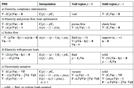
Lately, alternatives to the above described density approach have appeared. In level-set approaches mate-rial boundaries are described by the zero level-set surface and boundary optimiza-tion is obtained by solving of Hamilton-Jacobi equations [4]. Parameterized level-set functions allowing for the use of Math Programming approaches have also been suggested based on the use of radial basis functions [5]. The different approaches each have their pros and cons, however, common for all is that they are based on fictitious domain mod-eling and hence they require interpolation schemes for the correct modeling of the solid and void domains. In simple stiff-ness optimization problems this may not be a problem because the void domain has no influence on the structure. However, in other physics cases, the void domain may contain pressurized fluids, moving fluids, acoustic waves, electric fields, etc. If the topology was given, such modeling problems could easily be solved by staggered approaches, i.e. for a structural-acoustic problem, the Helmholtz and Navier equations could be solved separately in each their subdo-mains but coupled through boundary terms. In topology optimization, the boundaries are unknown a priori and hence staggered approaches are imprac-tical and must be substituted with mono-lithic approaches where all physics is modeled on the same mesh. In the fol-lowing we demonstrate how monolithic (non-staggered) analysis schemes suit-able for topology optimization of multi-physics problems can be based on suit-able interpolations of PDEs (Partial Differential Equations).
Elasticity
The first examples of topology optimiza-tion were based on minimum compliance design of mechanical structures. The PDE for elasticity without volume load is given in Table 1a. The design variable ρ interpolates between empty space (ρ=0) and solid material (ρ=1) governed by the elasticity PDE. In practice, this is done by letting the Young’s modulus or the whole stiffness tensor of solid material be a function of ρ.
A compliance minimization example for airplane wing-rib design is shown in
Figure 1. A range of other design prob-lems are also covered by this simple interpolation between void (empty space) and solid material. Examples are thermal and electric conduction problems and also multiphyscis problems like elec-trothermomechanical actuators [6].
Photonic crystals
A simple extension of the solid-void scheme is to have the same PDE gov-erning the solid and the void regions, i.e. the design variable interpolates between e.g. a low and a high value of refractive index as seen in the design of photonic crystals governed by Maxwell’s equations [7]. A photonic crystal based wave guide nano-scale splitter is shown in Figure 2.
Figure 2:
Elasticity and porous flow
It has long been known that human bone structure adapts to external loads and generates an-isotropic porous microstruc-tures. However, the exact objec-tive function behind the adaption is still not c l e a r l y u n d e r s t o o d although it is clear that com-peting objectives such as maxi-mum stiffness or strength as well as nutrition transport are in play. In order to study opti-mal
microstruc-tures governed by the porous flow PDE in the void region and the elasticity PDE in the solid regions, reference [8] suggested to interpolate between the two PDEs as seen in the Table 1b. With ρ=0 we obtain porous flow governed by Poisson’s equa-tion and with ρ=1 we obtain solid struc-ture governed by Navier’s equation. An example of micromechanical bone design with varying constraints on per-meability/conductivity is shown in
Figure 3.
Stokes flow
The extension of the topology optimiza-tion to fluid mechanics problems was not straightforward and has only been solved recently [9]. Following the ideas from elasticity, a first thought was to interpo-late the material property, i.e. the viscosi-ty between fluid and non-fluid region by switching between the physical viscosity of the relevant fluid and an infinitely high viscosity (non-fluid) region. However, this does not work since the high viscosity regions only will stop flow if they are attached to no-slip boundaries. A better solution proved to be to add a dissipa-tion (inverse
permeabili-Table 1: Monolithic PDE interpola-tion schemes for various physics problems.
Figure 3: Top: Cut through human hip bone. Bottom: results for topology
ty) term to the Stokes equation, i.e. turn-ing it into the Brinkman equation and then letting the design variable determine the magnitude of the dissipation term. As seen in Table 1c, switching the inverse permeability ρbetween 0 and infinity, one can interpolate between the pure Stokes flow equation (ρ=0) and no flow (ρ=1). Examples of topology optimization for flu-ids are shown inFigure 4.
Elasticity with pressure loads
Solving pressure load problems using the topology optimization is inherently a problem since it is unclear where to apply the pressure loads if the boundaries are unknown. In order to solve the problem previous works used various shape descriptors and boundary optimization techniques on top of the topology opti-mization parameterization. However, it has turned out [12] that a reformulation of the standard elasticity formulation into a mixed form makes it possible to solve the problem by simple interpolation between zero shear stiffness but finite bulk modu-lus (i.e. a compressible stationary fluid) in the pressurized void region and finite shear and bulk moduli in the solid region. The equations are given in Table 1d and an example is shown in Figure 5. The idea can also be extended to structural acoustic problems by the same interpola-tion of the mixed form but now including inertia terms [13].
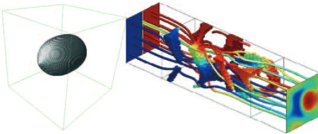
Electrostatic actuation
The last and most challenging example of a PDE interpolation for topology opti-mization, that we will discuss here, is the design of electrostatically actuated micro systems. Electrostatic forces between
two conductors are inversely proportional to the square of the gap between them, hence in micro scale these forces become large enough for mechanical actuation. Normally the electromechani-cal modeling problem is solved by stag-gered analysis approaches but recently it was shown that monolithic schemes amenable to topology optimization can be set up [14,15]. Table 1d shows the scheme that interpolates between the electrostatic Poisson’s equation (void regions) and the elasticity equations
(solid region). The boundary loads (Maxwell stresses) F generated by the electrostatic field enter the elasticity equation as volume loads. An example of electrostatic actuator design is shown in
Figure 6.
Figure 4:
Stokes flow examples. Left: minimizing drag of of given volume Figure 4: Stokes flow examples. Left: minimizing drag of obstacles of given volume (from [10]).
Right: a flow mixer with flow lines and colors indicating temperature from inlet (left) to outlet (right) (from [11])
Figure 5:
With these five examples it has been demonstrated how various multiphysics and boundary load problems can be posed in monolithic settings amenable to topology optimization formulations by proper interpolations between the gov-erning PDEs. It is the authors vision that any kind of physical design problem can be formulated in similar monolithic forms. Ideally, one would set up a table of all known PDEs and generate the proper interpolations between them. As long as the PDEs are formulated in the same coordinate systems this should indeed be possible.
However, when considering “incompati-ble PDEs” like for instance the fluid-struc-ture problem where the fluid problem is formulated in an Eularian coordinate sys-tem and the elastic problem is formulated in a Lagrangian system, the proper inter-polation scheme is not yet clear. Amongst others, it is the formulation and solution of such advanced incompatible coupled problems that constitute the future challenges within the field of topol-ogy optimization.
References:
[1] M. P. Bendsoe and N. Kikuchi. Generating optimal topologies in structural design using a homogenization method. Computer Methods in Applied Mechanics and Engineering, 71(2):197-224, 1988.
[2] G. Schuhmacher. Optimizing aircraft structures. Concept to Reality, Altair Engineering, winter:12-16, 2006. [3] M. P. Bendsoe and O. Sigmund. Material interpolation schemes in topology optimization.Archives of
Applied Mechanics, 69(9-10):635-654, 1999.
[4] J. A. Sethian and A. Wiegmann. Structural boundary design via level set and immersed interface methods. Journal of Computational Physics, 163(2):489-528, 2000.
[5] J. Norato, R. Haber, D. Tortorelli, and M.P. Bendsoe. A geometry projection method for shape optimization.
International Journal for Numerical Methods in Engineering, 60(14):2289-2312, 2004.
[6] O. Sigmund. Design of multiphysics actuators using topology optimization - Part I: One-material structures. Computer Methods in Applied Mechanics and Engineering, 190(49-50):6577-6604, 2001. [7] P. I. Borel, A. Harpøth, L. H. Frandsen, M. Kristensen, J. S. Jensen, P. Shi, and O. Sigmund. Topology
optimization and fabrication of photonic crystal structures. Optics Express, 12(9):1996-2001, 2004. http://www.opticsexpress.org/abstract.cfm?URI=OPEX-12-9-1996.
[8] O. Sigmund. On the optimality of bone microstructure. In P. Pedersen and M. P. Bendsöe, editors,
Synthesis in Bio Solid Mechanics, pages 221-234. IUTAM, Kluwer, 1999.
[9] T. Borrvall and J. Petersson. Topology optimization of fluids in Stokes flow. International Journal for Numerical Methods in Fluids, 41:77-107, 2003.
[10] N. Aage, T. H. Poulsen, A. Gersborg-Hansen, and O. Sigmund. Topology optimization of large scale Stokes flow problems. Structural and Multidisciplinary Optimization, 35:175-180, 2008.
[11] C. S. Andreasen, A. R. Gersborg, and O. Sigmund. Topoloy optimization of laminar fuid mixers. in preparation, 2008.
[12] O. Sigmund and P.M. Clausen. Topology optimization using a mixed formulation: An alternative way to solve pressure load problems. Computer Methods in Applied Mechanics and Engineering,
196(13-16):1874-1889, 2007.
[13] G. H. Yoon, J. S. Jensen, and O. Sigmund. Topology optimization for acoustic structure interaction problems. International Journal for Numerical Methods in Engineering, 70(9):1049-1075, 2007.
[14] A. Alwan and G.K. Ananthasuresh. Topology optimization of electrostatically actuated micromechanical structures with accurate electrostatic modeling of the interpolated material model. In
DETC2006-99684, 2006.
[15] G. H. Yoon and O. Sigmund. Topology optimization of electrostatic actuators. Computer Methods in Applied Mechanics and Engineering, 2008. to appear.
Figure 6: Topology optimization with electrostatics forces for MEMS. Left: design domain. Center: topology optimized
by
Roger Ohayon
Structural Mechanics &
Coupled Systems
Laboratory
Conservatoire National
dces Arts et Métiers
Paris - France
http://www.cnam.fr/lmssc/
H
istorical backgroundThe Conservatoire National des Arts et Métiers (Figure 1), is a higher education and research public establishment dedi-cated to providing education and con-ducting research for the promotion of sci-ence and industry. It has a large museum of inventions accessible to the public (Musée des Arts et Métiers).
It was founded by the abbot Henri Grégoire in 1794, during the French Revolution and is located on the old Benedictine priory of Saint-Martin-des-Champs (Merovingian period, 1060). The medieval perimeter wall can still be partially seen.
The Conservatoire National des Arts et Métiers is located in the IIIe arrondisse-ment of Paris, in the historical area of the city named Le Marais (Figure 2).
Research activities at the LMMSC
The research group entitled Structural Mechanics and Coupled System Labora -tory (in French Laboratoire de Mécanique des Structures et des Systömes Couplés, LMSSC) has been created in 1997 when Roger Ohayon left the Aerospace French Lab (ONERA) to join academia as Professor holding the Chair or Mechanics at CNAM, maintaining the research links with ONERA though PhD students. The Lab is involved in various projects with governmental French agencies (DGA, CNES, Ministry of Research), industries (EADS, SAFRAN ...), and European pro-jects (InMAR, Marie Curie SMART)
The members of the team are affiliated to IACM through the French Association of Computational Structural Mechanics (CSMA). They are also involved in ASME (Adaptive Structures Technical Committee) and AIAA societies.
Professor Roger Ohayon (Fellow IACM and Fellow ASME) is currently the head of the Lab.
Research Activities at the
S
tructural
M
echanics and
C
oupled
S
ystems
L
aboratory
Figure 1: Conservatoire National
des Arts et Métiers, Paris
The research activities of LMSSC (http://www.cnam.fr/lmssc) concern com-putational and experimental mechanics in the following domains:
- Linear and Non Linear Structural Dynamics and Vibration;
- Fluid Structure Interaction, Struc-tural Acoustics, Adaptive
Dissipative Interfaces;
- Vibration Reduction using Smart Structures and Intelligent Systems.
In the following, we illustrate some research activities concerning fluid struc-ture interaction problems and vibration reduction using dissipative interfaces and smart structures. For general references on fluid structure interaction and structur-al acoustic mechanicstructur-al and computation-al modelling, the reader can refer for instance to Refs.[8, 9, 10, 11].
Among the various applications, let us cite:
- hydroelastic and sloshing vibrations of liquids, for instance for aerospace industry, for propelled launch vehicles taking into account if necessary surface tension effects which occur in stability studies and in vibration studies of satellites, spacecrafts, airplanes…
- structural-acoustic vibrations
occurring in the payload of
launchers (due to engine noise), in fuselage of aircraft, in automobiles.
The particularity of the problems under consideration lies in their multiphysic and multiscale aspects due to the disparity of wavelengths in the structure (metallic or composite) and fluid domains. The fluid structure coupled system may be submit-ted to various types of dynamic excita-tions (see
Figure 3)
The numerical methods developed here-in are of here-interest for various here-industrial domains, such as automotive industry engineering, nuclear engineering, civil engineering, naval engineering, biome-chanics,…
Various symmetric matrix equations derived from appropriate variational for-mulations by means of the finite element method have been