Performance Comparison of Zinc-Carbon Accumulator and Yuasa
Accumulator Model 6N4-2A-4
Kurriawan Budi Pranata
1, Sudi Dul Aji
2, Endarko
31Department of Physics Education, University of Malang Kanjuruhan (UNIKAMA) Jl. SoedancoSupriadi No.48–[email protected]
2Department of Physics Education, University of Malang Kanjuruhan (UNIKAMA) Jl. SoedancoSupriadi No.48– [email protected]
3Department of Physics, Institute of Technology SepuluhNopember Surabaya KeputihSukolilo Surabaya 60111 - [email protected]
ABSTRACT
Performance comparison of Zinc-Carbon accumulator and Yuasa Accumulator Model 6N4-2A-4 have been successfully studied. The accumulator has been fabricated using Zn-C as electrode which consists of 3 cells and sulfuric acid as an electrolyte. Two configurations were used to assembly the cell namely series configuration and parallel configuration. The aim study was to determine energy efficiency of the accumulators. Three types accumulator will be tested for charging and discharging performances to measure an average energy efficiency namely Zinc-Carbon Accumulator with series configuration, Zinc-Carbon Accumulator with parallel configuration and Yuasa Accumulator Model 6N4-2A-4. Operational voltage for the accumulators were 1.39 – 7.96 V, 1.06 – 2.69 V and 1.73 – 7.55 V, respectively. Charging and discharging performances were measured and analyzed using three cycles for 36 hours. The results showed that Yuasa Accumulator Model 6N4-2A-4 is better than both the accumulators regarding the average energy efficiency. The average energy efficiency for Yuasa Accumulator Model 6N4-2A-4 can be achieved at 67.9 % whereas Zinc-Carbon Accumulator with series configuration and Zinc-Carbon Accumulator with parallel configuration resulted in 35.3 % and 63.3 %, respectively.
Figure: 4 Constant current discharge characteristics of Zinc - Carbon series configuration, parallel configuration and Yuasa Model 6N4-2A-4.
1. Introduction
Electrodes Zinc - Carbon is a constituent material of alkaline batteries that have the nature of non-rechargeable batteries or primary cell battery, it is designed to be fully discharged only once, and then discarded [1]. People usually use and throw it carelessly so that it gives a very bad impact on the environment, it is because the content of the spent primary cell batteries generate specific residues such as mercury, zinc, manganese and other heavy metals [2], which is very susceptible to damage the environment and threaten public health [3].
Increased environmental awareness and consumption of raw materials led to tightened regulations on primary batteries worldwide. These rules and various things of issues - environmental issues pushed to collect the spent primary battery aimed to recovery of further use of metal [4]. One is in Turkey; the regulations on the Control of Spent Battery and Accumulators was published on August 2004 [5]. In Indonesia, regulations on environmental pollution by dry cell batteries have been published by the decision of environmental state minister and provincial regulation in Yogyakarta No. 2 of
2012 on the management of hazardous wastes and toxic [6,7,8].
Based on the regulation on environment ministers, Zinc is one of the hazardous heavy metals that pollute the environment [6]. So in this study, zinc metal developed to be active material as a concept of energy storage technique that is shaped like an accumulator. In the previous studies have been developed as an active material of a secondary battery design [9,10,11].
Likewise with carbon electrodes are also used previous studies as an inert material that has an influence as the good collector current behavior in the lead acid battery system [12,13,14]. Electrode system design uses a sandwich models, as is done on the research [15,16]. In this study is continued by comparing the performance of the Yuasa Accumulator Model 6N4-2A-4, by means of charge- discharge cycle test with a constant current of 0.5 A total of three cycles for 36 hours.
2. Experimental details
electrode with a 94% level with dimensions of 7 x 4.5 cm2 up to 12 plates. Connecting process at zinc plate bonded with tin trunk that has dimensions of 28 x 4.5 cm2 as well as carbon plate with the same connecting treatment. Both electrodes are stacked into one like sandwich model and between the two sides were given a separator made of insulator material so that the two are not in contact with each other as is done in research [15,16]. This pile is composed of three layers with the configuration Zn | C | Zn. This electrode layer configuration was put into a cell with dimensions of 6 x 5 x 32 cm3 in which there is a solution of sulfuric acid.
Z
Fig 1. Diagram Blog Cell System
Figure 1 shows a block diagram of the accumulator cell system design inspired in research [17,18]. In this study is consisted of three cell system in which each one cell system connected in series with the pipe.
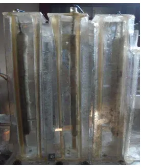
Fig 2. Construction Accumulator Zn- C
In Figure 2 shows the construction of the accumulator that has been created using a transparent acrylic material with the aim to simplify the process of observation. Each accumulator cell construction is made with acrylic rectangular block with dimensions of 6 × 5 × 32 cm3, in which there is a solution of sulfuric acid electrolyte, which consists of three cells in order to do the preparation of cells in series and parallel. Methods of data retrieval accumulator cell potential uses method of constant current charge-discharge as many as three cycles for 36 hours.
3. Results and discussions
3.1. Discharging process
discharge reaction on both electrodes is as follows [20,21,22]:
Cathode: O2 (g) + 4H+ (aq) +4e → 2H2O (l) Eo = +1,23 V Anode: 2Zn (s) → 2Zn2+ + 4e
Eo = - 0,76 V
Reaction Cells: 2Zn (s) + O2 (g) + 4H+ (aq)→ 2Zn2+ + 2H2O (l)
EoCell = +1,99 V
In the discharging process, both electrodes are given a specific load as illustrated in Figure 3. As result, discharging happens indicated by declining accumulator cell voltage as shown in Figure 4. The chemical reaction at the discharge process is indicated by the formation of hydrogen bubbles (H2 gas) at positive pole shown in Figure 3.
Fig 3. illustration of discharging process
On the negative pole Zink metal at room temperature have a solid form and has a negative standard potential (E ° = - 0.76 V) [21], it means that zinc metal is easily oxidized by releasing two electrons forming Zn2+ ions. Zn2+ ions will react with sulfuric acid to form ZnSO4 and generating hydrogen gas according to the following reaction [19,22].
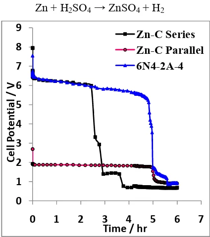
Zn + H2SO4 → ZnSO4 + H2
Fig 4. Graph discharge characteristics.
In Figure 4, shows that the cell energy generated Yuasa Accumulator Model 6N4-2A-4 is greater than the Accumulator Zn-C series, but the time span discharge process between Yuasa accumulator 6N4-2A Model-4 and Accumulator Zn-C parallel has span time is almost the same. Based on the curves in Figure 4, the operational voltage
0 1 2 3 4 5 6 7 8 9
0 1 2 3 4 5 6 7
Cel
l P
ot
en
tia
l /
V
Time / hr
Yuasa Accumulator Model 6N4-2A 4th is 1.73 Volt to 7.55 Volt. Accumulator Zn-C series is 1.39 volts to 7.96 volt, accumulator parallel is 1.06 Volt to 2.69 Volt.
3.2 Charging Process
In the charging process either Zn - C Accumulator or Yuasa Accumulator Model 6N4-2A-4 is given electric current in the electrode. Illustration of charging process Zn - C Accumulator in Figure 5.
Fig 5. Illustration the charging process In Figure 5, a chemical reaction occurs at both electrodes so that there is a process of charge storage on both electrode indicated by rising accumulator cell voltage as shown in Figure 6. The charging proses follows the chemicals reaction as follows.
Cathode: 2Zn2+ + 4e → 2Zn (s)
Anode : 2H2O (l) → O2 (g) + 4H+ (aq) +4e Reaction total : 2Zn2+ + 2H2O (l) → 2Zn (s)
+ O2 (g) + 4H+ (aq)
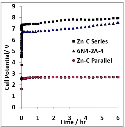
Fig 6. Graph charging characteristics.
Chemical process that happens is the opposite of the process of discharging. At the anode occurs oxidation reaction, the water will form oxygen gas. Furthermore, the zinc cathode ZnSO4 is reduced forming solids Zinc. This happens because the carbon electrode is an inert material, which means it will not dissolve in acidic or alkaline solution so that there is no reaction. Because the electrolyte used is sulfuric acid electrolyte that have negative ion SO42- then water reacts at the anode. While on the cathode metal ions Zn2+ has a smaller potential than water reducible form a solid metal [20]. In Figure 6 shows the charging energy consumption in the Zn - C Accumulator series is bigger than all the graphs voltage charging performance
0 1 2 3 4 5 6 7 8 9
0 1 2 3 4 5 6
Cel
l P
ot
en
tia
l/
V
Time / hr
accumulators Zn - C parallel and Yuasa Accumulator Model 6N4-2A-4.
3.3Charge/discharge performance of a zinc– carbon accumulator
Test of charge/ discharge cycle is done to look at the performance of each type of Accumulator.
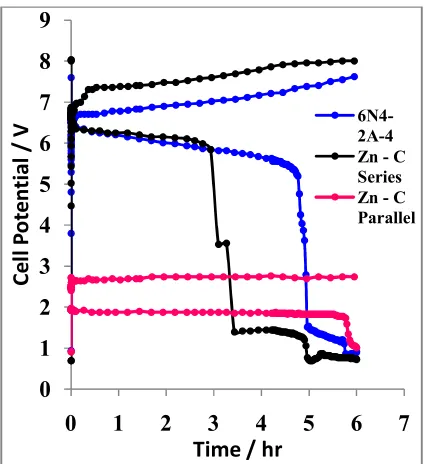
Fig 7. Charge/ discharge graph of the second cycles
Based on reference of the technical specifications data of Yuasa Model 6N4-2A-4 states that discharging duration required for 0.5 Ampere [24]. So that this data can be used as a reference for comparison with Zn-C Accumulator.
In Figure 7 and 8 shows that the charging energy consumption at Accumulator charging Zn - C series is still
bigger than all graphs of performance voltage Zn - C Accumulator parallel and Yuasa Accumulator Model 6N4-2A-4. Furthermore, discharge time Zn - C Accumulator series become shorter as shown in Figure 8. On the contrary Zn - C Accumulator parallel have discharge time longer than Yuasa Accumulator Model 6N4-2A-4 and Zn - C Accumulator series.
Fig. 8. Graph charge / discharge on the third cycles
In the cell parallel circuit configuration can add sectional area of the metal electrode so that Zink can reproduce Zink metal oxidation reaction and increase the amount of formation of Zn2+ ion to react with sulfuric acid to form ZnSO4.
In Figure 9, shows the test result of charge/discharge cycles in each accumulator of three cycles for 36 hours. Zn - C Accumulator parallel has the best performance. The longer carried out the process of charge - discharging for 3 cycles, the curve of surface area during discharge is getting bigger indicated discharging time longer.
Fig. 9. Cell voltage vs. time response for three charge/discharge cycles at constant
current 0.5 A.
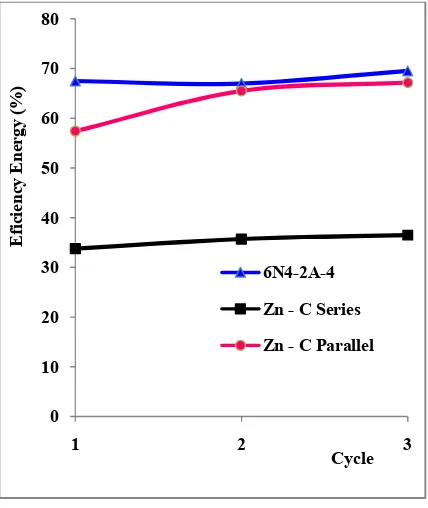
Based on testing 3 cycles of charging-discharging, the calculations using the equations as in the research [23], the value of the average energy efficiency of each accumulator is 35.3% (Zn - C series), 63.3% (Zn - C parallel), and 67.9% (Yuasa
Model 6N4-2A -4), respectively. It can also be shown in Figure 10.
Fig. 10. Graph of Energy Efficiency on Percentage toward number of cycles.
In Figure 10, shows the efficiency energy value of each cycle, that the Yuasa Accumulator Model 6N4-2A-4) has the most excellent efficiency values of the Zn-C accumulator with series and parallel configuration.
4. Conclusions
Three types accumulator is tested for charging and discharging performances to measure average energy efficiency namely Zinc-Carbon Accumulator with series configuration, Zinc-Carbon Accumulator
0 10 20 30 40 50 60 70 80
1 2 3
E
fic
ie
nc
y
En
er
gy
(%
)
with parallel configuration and Yuasa Accumulator Model 6N4-2A-4. From this studied, electrodes Zn-C has been proven to be used as the active material in the design of the accumulator. Some research has been done can be summarized as follows:
1. Operational voltage for each accumulators were 1.39 – 7.96 V (Zinc – Carbon series configuration), 1.06 – 2.69 V (Zinc – Carbon parallel configuration) and 1.73 – 7.55 V (Yuasa Accumulator Model 6N4-2A-4).
2. The process of charge - discharging is performed 3 times over 36 hours on each type of accumulator. As result, Yuasa accumulator Model 6N4-2A-4 has the best performance.
3. The average energy efficiency for Yuasa Accumulator Model 6N4-2A-4 can be achieved at 67.9 % whereas Zinc-Carbon Accumulator with series configuration and Zinc-Carbon Accumulator with parallel configuration resulted in 35.3 % and 63.3 %, respectively.
References
[1] Rayovac Corp., 1999. Material safety data sheet. Available from http:/ /rayovac.com
[2] Bartolozzi, M., 1990. The recovery of metals from spent alkaline-manganese batteries: a review of
patent literature. Resour. Conserv. Recycl. 4, 233–240.
[3] Kierkegaard, S., 2007. EU Battery Directive, charging up the batteries: squeezing more capacity and power into the new EU Battery Directive. Comput. Law Secur. Rep. 23, 357– 364.
[4] E. Sayilgan, T. Kukrer, F. Ferella, A . Akcil, F. Veglio, M. Kitis., Reductive leaching of manganese and zinc from spent alkaline and zinc–carbon batteries in acidic media. Hydrometallurgy 97 (2009) 73 –79. [5] Turkish Ministry of Environment and
Forestry, 2005. Directive of the Con trol of Spent Battery and Accumulators (in Turkish).
[6] Keputusan Menteri Negara Lingkungan
Hidup Nomor : KEP –
51/MENLH/10/1995/Tentang Baku Mutu Limbah Cair Bagi Kegiatan Industri
[7] Peraturan Menteri Lingkungan Hidup Republik Indonesia Nomor 5 Tahin 2014 Tentang Baku Mutu Air Limbah.
[8] Peraturan Daerah Provinsi Daerah Istimewa Yogyakarta Nomor 2 Tahun 2012 Tentang Pengelolaan Limbah Bahan Berbahaya dan Beracun. [9] Ruijuan Wang, Zhanhong Yang, Bin
[10] M. Xu, D.G. Ivey, Z. Xie, W.Qu. Rechargeable Zn-air batteries: Progress in electrolyte development and cell configuration advancement. Journal of Power Sources 283 (2015) 358-371.
[11] Georgios Nikiforidis, Léonard Berlouis,
David Hall, David
Hodgson.Charge/discharge cycles on Pt and Pt-Ir based electrodes for thepositive side of the Zinc-Cerium hybrid redox flow battery. Electrochimica Acta 125 (2014) 176–182.
[12]A. Czerwi´nski, S.Obrebowski, J. Kotowski, Z. Rogulski, J. Skowro´nski, M. Bajsert,M. Przystałowski, M. Buczkowska-Biniecka, E. Jankowska, M. Baraniak, J. Rotnicki, M. Kopczyk. Hybrid lead-acid battery with reticulated vitreous carbon as a carrier- and current-collector of negative plate. Journal of Power Sources 195 (2010) 7530–7534. [13] Andrzej Czerwi ´nski, Szymon
Obrebowski, Zbigniew Rogulski. New high-energy lead-acid battery with reticulated vitreous carbon as a carrier and current collector. Journal of Power Sources 198 (2012) 378– 382.
[14] D. Pavlov, P. Nikolov, T. Rogachev. Influence of carbons on the structure of the negative active material of lead-acid batteries and on battery performance. Journal of Power Sources 196 (2011) 5155–5167. [15] Tao Huang, Wenjun Ou, Bo Feng,
Binbin Huang, Minyi Liu,
Wenchao Zhao, Yonglang Guo. Researches on current distribution and plate conductivity of valve-regulated lead-acid batteries. Journal of Power Sources 210 (2012) 7– 14.
[16] C. Justin Raj, K.B.R. Varma. Synthesis and electrical properties of the (PVA)0.7 (KI)0.3·xH2SO4 (0 ≤ x ≤ 5) polymer electrolytes and their performance in a primary Zn/MnO2 battery. Electrochimica Acta 56 (2010) 649–656.
[17] Fritz Beck and Holger Khorn. A lead/graphite accumulator using aqueous hydrofluoric acid. Journal of Power Sources, 12 (1984) 9 - 30. [18] P. Kurzweil. Gaston Planté and his
invention of the lead–acid battery— The genesis of the first practical rechargeable battery. Journal of Power Sources 195 (2010) 4424– 4434.
[19] Peng Chang-hong, Bai Ben-shuai, Chen Yi-feng. Study on the preparation of Mn–Zn soft magnetic ferrite powders from waste Zn–Mn dry batteries. batteries by reductive leaching in acidic media. Journal of Power Sources 247 (2014) 612-617.
redox flow battery. Electrochimica Acta 140 (2014) 139–144.
[22] Traian Buzatu, Gabriela Popescu, Ionela Birloaga, Simona Sa˘ceanu. Study concerning the recovery of zinc and manganese from spent batteries by hydrometallurgical processes. Waste Management 33 (2013) 699–705. [23]Xiangguo Teng, Cui Sun, Jicui Dai,
Haiping Liu, Jing Su, Faqiang Li. Solution casting Nafion/ polytetrafluoroethylene membrane for vanadium redox flow battery application. Electrochimica Acta 88 (2013) 725– 734.